6 layers157.8 × 95.2 mm
Covg daq v2
lucask07/open_covg_daq_pcb
DAQ (ADCs and DACs) PCB for the digital ion channel amplifier project.
600 parts9GPL-3.0

 ra0sms/picorx_digi6
SDR receiver for Digi modes
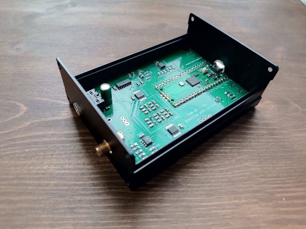
Pico rx is an open-source printed circuit board by ra0sms, from the ra0sms/picorx_digi repository on GitHub, published under the MIT licence. It is a 2-layer board of 100 × 70 mm with 79 parts on 105 nets, routed with 617 tracks and 136 vias.
It is built around the OPA1662AID, FST3253M and LTC6226IS6. Its parts include 33 capacitors, 16 resistors, 10 inductors, 6 ICs and 4 connectors. It belongs with the radio and wireless boards and the RP2040 boards of this library.


This is a clone of Jon Dawson's project PicoRX SDR.
But I wanted to make a simple DIGI (WSPR, FT8) receiver. This modification works with PC and WSJT-X software by one USB Type-C cable. 3.5 mm audio output is just for sound control. Audio from receiver to PC goes through USB connection.
More information - https://ra0sms.com/picorx-digi-modes
Firmware for 3 type of boards - https://github.com/ra0sms/picorx_digi/tree/main/firmware
Gerber files - https://github.com/ra0sms/picorx_digi/blob/main/KiCad/pico_rx/gerber_picorxdigi.zip
More pictures - https://github.com/ra0sms/picorx_digi/tree/main/pics
Schematic - https://github.com/ra0sms/picorx_digi/blob/main/KiCad/pico_rx/pipicorx.pdf
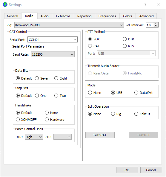
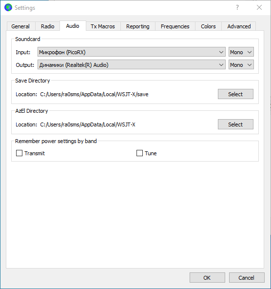
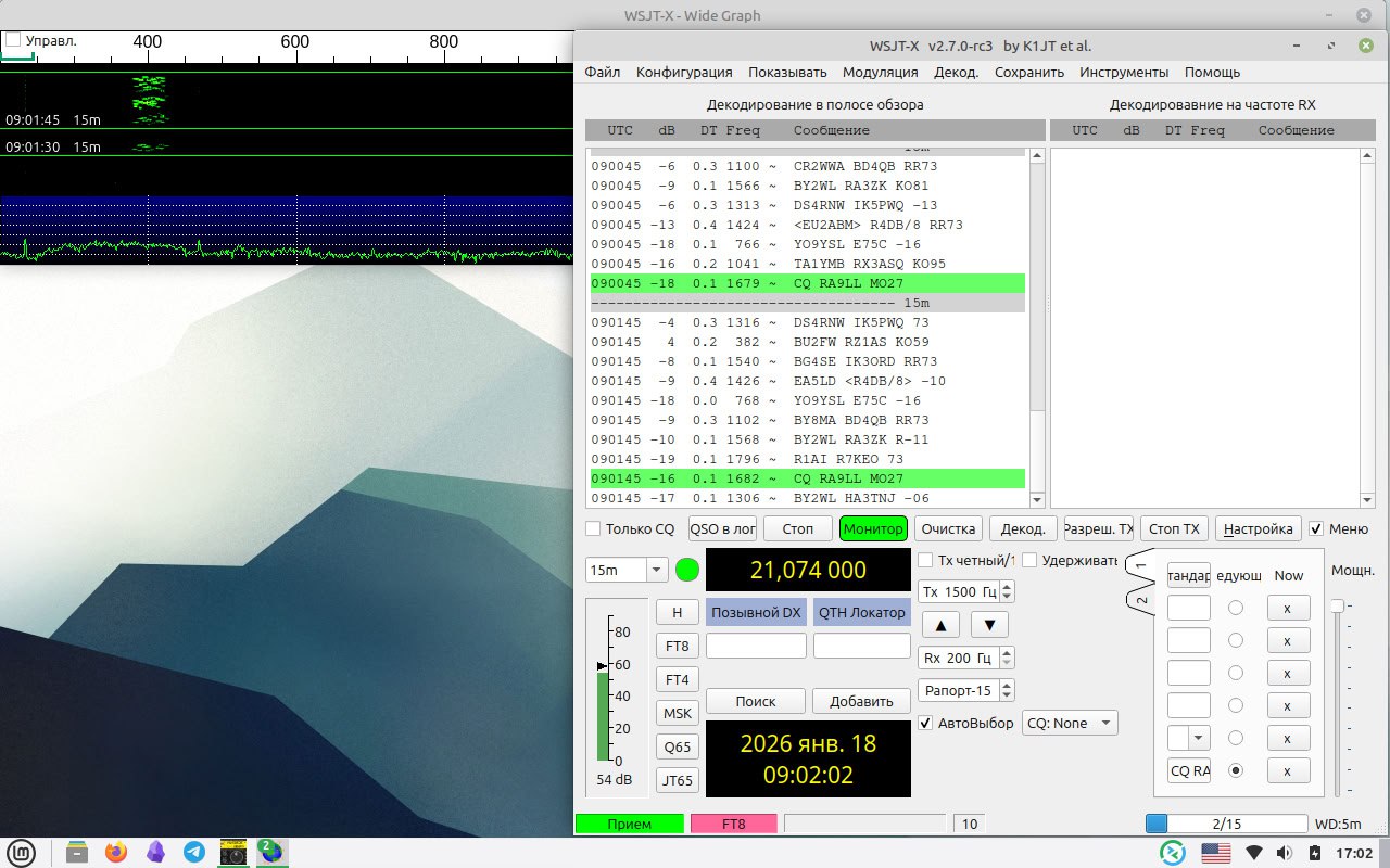
You need to connect receiver to PC by USB cable. And select COM-port and Audio input like on the pictures below.
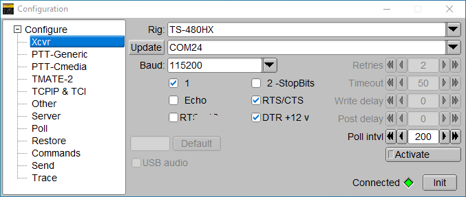
Or if you use FLrig software
Now you can see decodes.
This script (script/wspr_decoder.py) allows you to run automatic WSPR decoding on any single-board computer without a GUI (raspberry pi, nanopi, orange pi and etc.). The script implements band hopping and automatically sends spots to wsprnet.org. Edit the configuration file (wspr_config.json) before running.
You need to install wsjtx and python3-serial before running.
sudo apt install -y wsjtx python3-serialYou need to use the latest firmware - picorx_with_reset_cmd.uf2
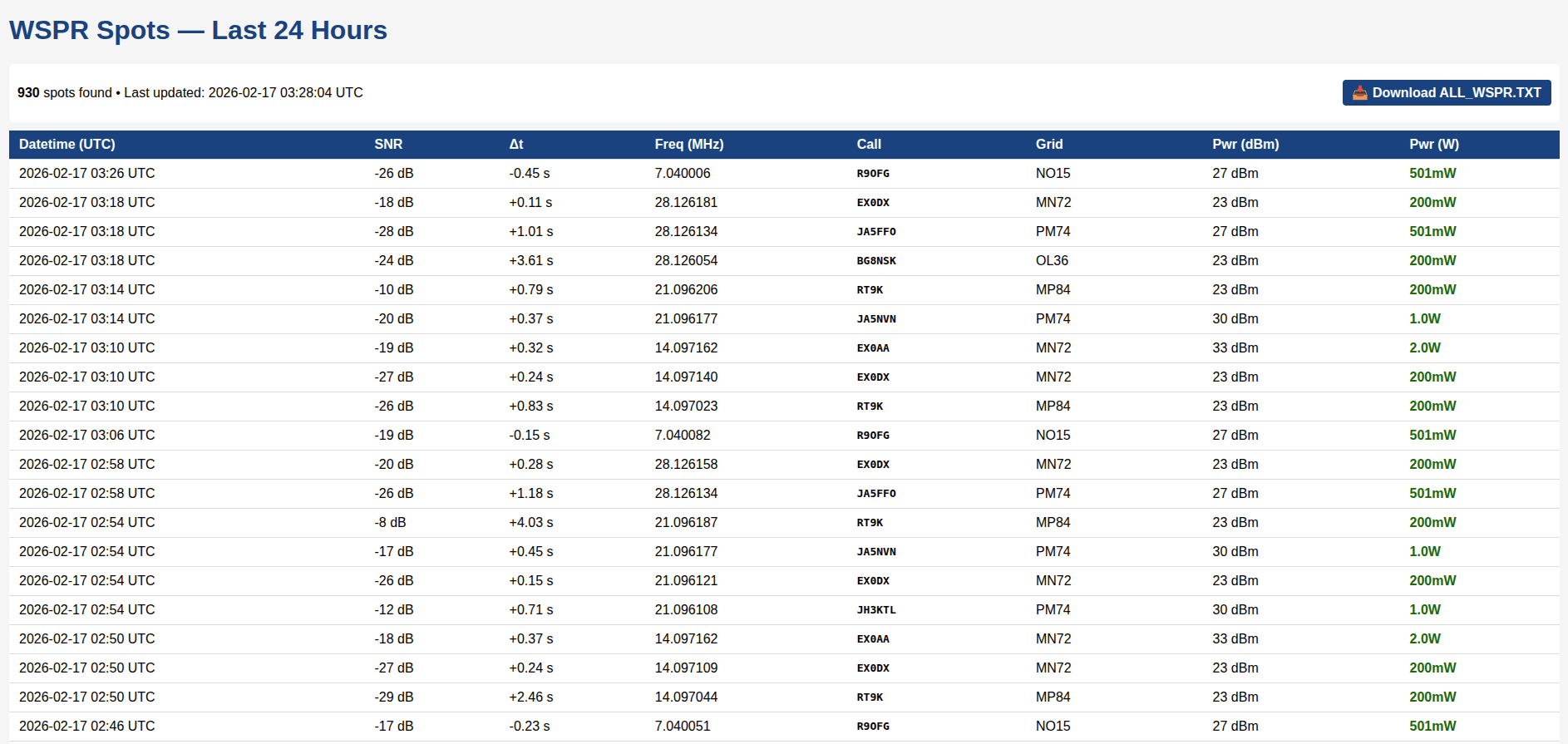
Web interface for any wspr receiver. Put wspr_web.py into WSJT-X directory and write the path in the script:
WSPR_FILE = "/path_to_file/ALL_WSPR.TXT"The web interface is available on http://YOUR_IP_WITH_ADDRESS_WITH_WSPRD:8080
Example:
| Qty | Value | Footprint | References |
|---|---|---|---|
| 6 | 100n | Capacitor_SMD:C_1206_3216Metric | C2, C3, C10, C17, C24, C25 |
| 4 | 100 | Resistor_SMD:R_1206_3216Metric | R3, R4, R5, R6 |
| 4 | 15n | Capacitor_SMD:C_1206_3216Metric | C26, C27, C28, C29 |
| 4 | 1n | Capacitor_SMD:C_0805_2012Metric | C7, C13, C14, C15 |
| 4 | MountingHole_Pad | MountingHole:MountingHole_3.2mm_M3_Pad | H1, H2, H3, H4 |
| 3 | 1k | Resistor_SMD:R_1206_3216Metric | R12, R15, R16 |
| 2 | 1.5n | Capacitor_SMD:C_0805_2012Metric | C19, C22 |
| 2 | 100k | Resistor_SMD:R_1206_3216Metric | R7, R8 |
| 2 | 10K | Resistor_SMD:R_1206_3216Metric | R2, R10 |
| 2 | 10u | Capacitor_SMD:C_1206_3216Metric | C4, C11 |
| 2 | 1u | Inductor_SMD:L_0805_2012Metric_Pad1.05x1.20mm_HandSolder | L3, L4 |
| 2 | 2.2u | Inductor_SMD:L_0805_2012Metric_Pad1.05x1.20mm_HandSolder | L6, L7 |
| 2 | 220n | Inductor_SMD:L_0805_2012Metric_Pad1.05x1.20mm_HandSolder | L5, L13 |
| 2 | 27p | Capacitor_SMD:C_1206_3216Metric | C30, C31 |
| 2 | 3.3n | Capacitor_SMD:C_0805_2012Metric | C36, C38 |
| 2 | 330n | Inductor_SMD:L_0805_2012Metric_Pad1.05x1.20mm_HandSolder | L1, L2 |
| 2 | 4.7u | Inductor_SMD:L_0805_2012Metric_Pad1.05x1.20mm_HandSolder | L8, L9 |
| 2 | 470 | Resistor_SMD:R_1206_3216Metric | R13, R14 |
| 2 | 680p | Capacitor_SMD:C_0805_2012Metric | C6, C9 |
| 2 | 74CBT3251 | Package_SO:SSOP-16_5.3x6.2mm_P0.65mm | U1, U2 |
| 2 | Ferrite_Bead | Inductor_SMD:L_1206_3216Metric | FB1, FB2 |
| 2 | SW_Push | Button_Switch_THT:SW_Tactile_SPST_Angled_PTS645Vx31-2LFS | SW2, SW3 |
| 1 | 100 | Resistor_SMD:R_0805_2012Metric | R9 |
| 1 | 100u | Capacitor_THT:CP_Radial_D5.0mm_P2.50mm | C39 |
| 1 | 10n | Capacitor_SMD:C_1206_3216Metric | C1 |
| 1 | 2.2n | Capacitor_SMD:C_0805_2012Metric | C21 |
| 1 | 220 | Resistor_SMD:R_1206_3216Metric | R11 |
| 1 | 22p | Capacitor_SMD:C_1206_3216Metric | C5 |
| 1 | 330p | Capacitor_SMD:C_0805_2012Metric | C16 |
| 1 | 330pF | Capacitor_SMD:C_0805_2012Metric | C8 |
| 1 | 4.7n | Capacitor_SMD:C_0805_2012Metric | C37 |
| 1 | 47 | Resistor_SMD:R_1206_3216Metric | R1 |
| 1 | 470n | Capacitor_SMD:C_0805_2012Metric | C34 |
| 1 | 470p | Capacitor_SMD:C_0805_2012Metric | C12 |
| 1 | Antenna | Connector_Coaxial:SMA_BAT_Wireless_BWSMA-KWE-Z001 | J5 |
| 1 | FST3253 | Package_SO:SOIC-16_3.9x9.9mm_P1.27mm | U4 |
| 1 | Fuse | Inductor_SMD:L_1206_3216Metric | F1 |
| 1 | Headphone | reciever:jack3.5mm switched | J2 |
| 1 | I2C Display | reciever:SDD1306 | J4 |
| 1 | LTC6226 | Package_SO:SO-8_3.9x4.9mm_P1.27mm | U6 |
| 1 | OPA1662 | Package_SO:SO-8_3.9x4.9mm_P1.27mm | U3 |
| 1 | Raspberry Pico | reciever:RPi_Pico_SMD_TH | U5 |
| 1 | RotaryEncoder_Switch | Rotary_Encoder:RotaryEncoder_Alps_EC11E-Switch_Vertical_H20mm | SW1 |
| 1 | Speaker | Connector_PinHeader_2.54mm:PinHeader_1x02_P2.54mm_Vertical | J1 |
lucask07/open_covg_daq_pcb
DAQ (ADCs and DACs) PCB for the digital ion channel amplifier project.

fu5ha/rgba
Reasonably Good Bluetooth Audio - A tiny, inline Bluetooth audio receiver for IEMs.


rf-designers/transceiver
Repository containing the design for the YO6SSW SDR transceiver, version 2


It measures 100 × 70 mm and has 2 copper layers, 1.6 mm thick.
79 parts, built around the OPA1662AID, FST3253M and LTC6226IS6. The full list of its parts is on this page, with links to each part's symbol and footprint where PCBKit's library has them.
From the ra0sms/picorx_digi repository on GitHub, at the commit this page was made from: the board is KiCad/pico_rx/pico_rx.kicad_pcb and its schematic KiCad/pico_rx/Lowpass.kicad_sch. PCBKit opens the board in the browser, with nothing to install.
Its repository publishes it under the MIT licence: you may reuse it on that licence's terms (keep the author's notice, and for a copyleft licence share your changes alike).