4 layers243.8 × 171.5 mm

 r-pv/STM32F030K611
Custom board for the STM32F30K6T6 MCU, compatible with STM32Duino (Arduino).
RSTM32F030K6T6 is an open-source printed circuit board by r-pv, from the r-pv/STM32F030K6 repository on GitHub, published under the GPL-3.0 licence. It is a 2-layer board of 22 × 41 mm with 23 parts on 39 nets, routed with 293 tracks and 4 vias.
It is built around the STM32F030K6T6, AMS1117 and MBR0530. Its parts include 5 capacitors, 5 resistors, 5 connectors, 3 diodes and 2 ICs. It belongs with the microcontroller boards boards and the STM32 boards of this library.


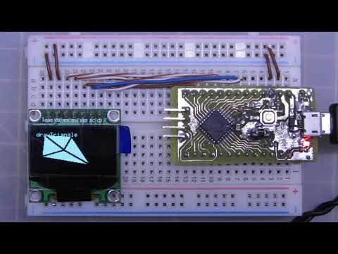
An ST development board based on the rSTM32F030K6T6/rSTM32F030K6 (Clock: 48MHz, flash: 32Kb, Ram:4Kb) MCU (LQFP-32) compatible with STM32Duino (Arduino).
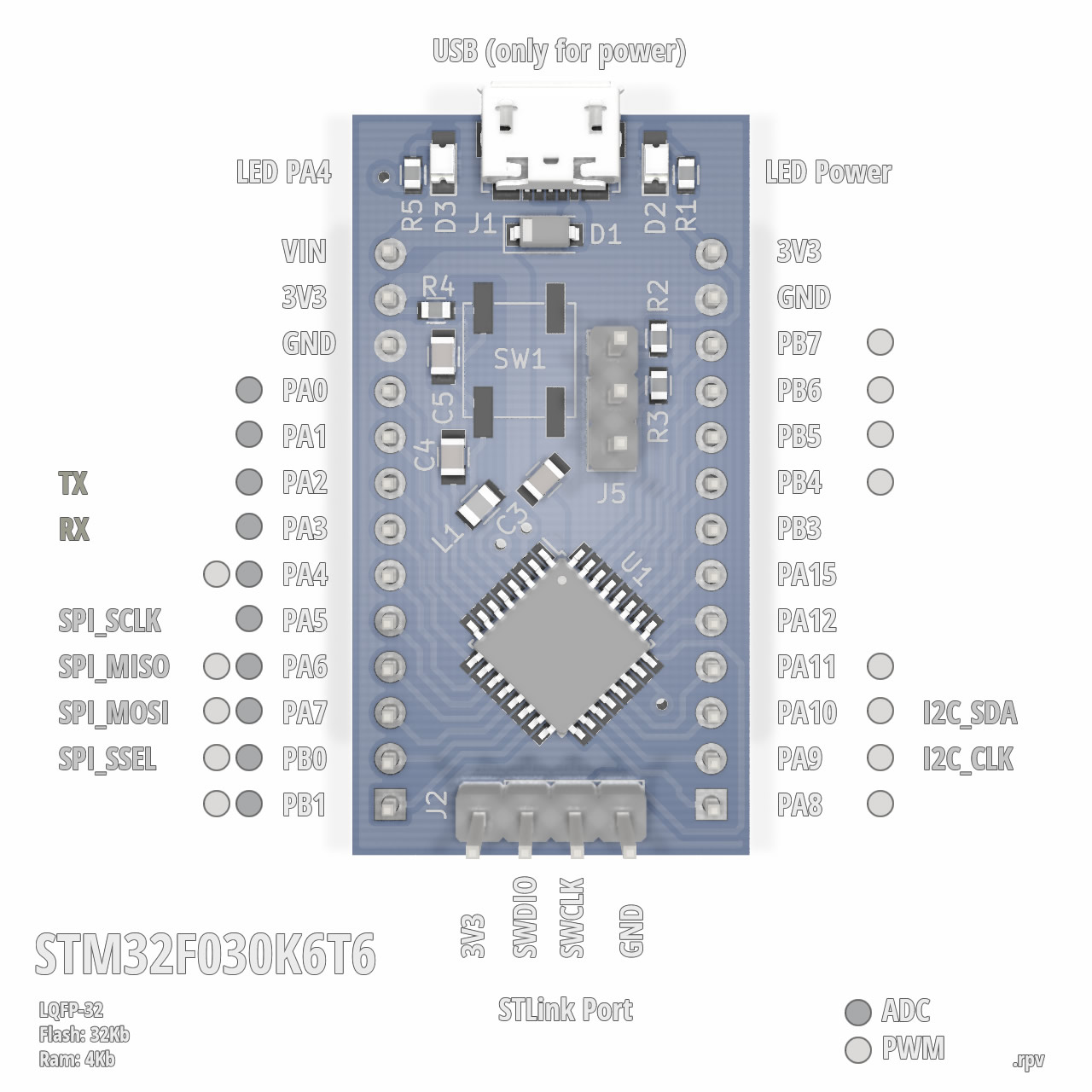
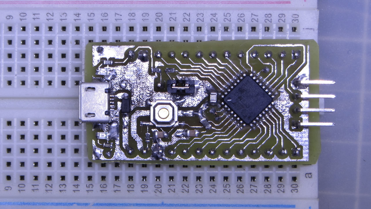
Update: STCore v2.0 includes support for this MCU, if you're using STCore v2.0 you don't need to install anything.
# DEMO_F030F4 board
# Support: Serial1 (USART1 on PA3, PA2)
GenF0.menu.pnum.DEMO_F030F4=STM32F030F4 Demo board
GenF0.menu.pnum.DEMO_F030F4.upload.maximum_data_size=4096
GenF0.menu.pnum.DEMO_F030F4.upload.maximum_size=16384
GenF0.menu.pnum.DEMO_F030F4.build.mcu=cortex-m0
GenF0.menu.pnum.DEMO_F030F4.build.board=DEMO_F030F4
GenF0.menu.pnum.DEMO_F030F4.build.series=STM32F0xx
GenF0.menu.pnum.DEMO_F030F4.build.product_line=STM32F030x6
GenF0.menu.pnum.DEMO_F030F4.build.variant=DEMO_F030F4
GenF0.menu.pnum.DEMO_F030F4.build.cmsis_lib_gcc=arm_cortexM0l_math

# DEMO_F030K6 board
# Support: Serial1 (USART1 on PA3, PA2)
GenF0.menu.pnum.DEMO_F030K6=STM32F030K6 Demo board
GenF0.menu.pnum.DEMO_F030K6.upload.maximum_data_size=4096
GenF0.menu.pnum.DEMO_F030K6.upload.maximum_size=32768
GenF0.menu.pnum.DEMO_F030K6.build.mcu=cortex-m0
GenF0.menu.pnum.DEMO_F030K6.build.board=DEMO_F030K6
GenF0.menu.pnum.DEMO_F030K6.build.series=STM32F0xx
GenF0.menu.pnum.DEMO_F030K6.build.product_line=STM32F030x6
GenF0.menu.pnum.DEMO_F030K6.build.variant=DEMO_F030K6
GenF0.menu.pnum.DEMO_F030K6.build.cmsis_lib_gcc=arm_cortexM0l_math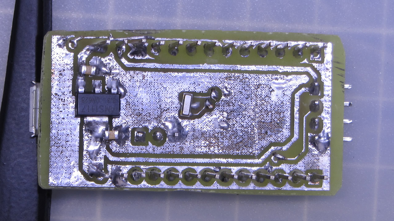
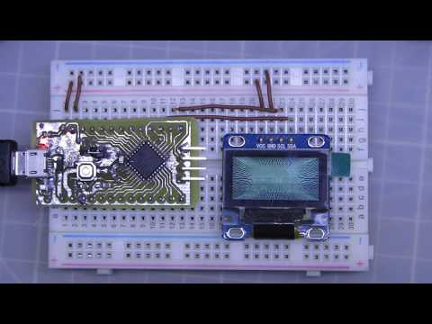
For some reason it seems that the sketchs for this platform gets way too fat (relative to standard arduino-atmel sketch sizes) and on some cases won't fit well on our board, a way to fit the sketchs to the flash/ram size that this board has it's to create a file hal_conf_extra.h on the sketch folder and disabling all features that weren't using:
#define HAL_ADC_MODULE_DISABLED
#define HAL_I2C_MODULE_DISABLED
#define HAL_RTC_MODULE_DISABLED
#define HAL_SPI_MODULE_DISABLED
#define HAL_TIM_MODULE_DISABLED
#define HAL_DAC_MODULE_DISABLED
#define HAL_EXTI_MODULE_DISABLED
#define HAL_ETH_MODULE_DISABLED
#define HAL_SD_MODULE_DISABLED
#define HAL_QSPI_MODULE_DISABLED
(an arduino restart may be required on changes to this file).
Also, if you aren't using the serial you cand disable it on the arduino menu:
Board > U(S)ART Support > Disabled.
This it's the first board variant I made, so errors may occur.
| Qty | Value | Footprint | References |
|---|---|---|---|
| 2 | Pin_Headers:Pin_Header_Straight_1x13_Pitch2.54mm | J3, J4 | |
| 2 | 100nF | Capacitors_SMD:C_0805 | C4, C5 |
| 2 | 10K | Resistors_SMD:R_0603 | R2, R4 |
| 2 | 22uF | Capacitors_SMD:C_0805 | C1, C2 |
| 2 | 4K91 | Resistors_SMD:R_0603 | R1, R5 |
| 2 | LED | LEDs:LED_0805 | D2, D3 |
| 1 | 10uF | Capacitors_SMD:C_0805 | C3 |
| 1 | 10uH | Inductors_SMD:L_0805 | L1 |
| 1 | 560R | Resistors_SMD:R_0603 | R3 |
| 1 | AMS1117 | TO_SOT_Packages_SMD:SOT-223-3_TabPin2 | U2 |
| 1 | BOOT | Pin_Headers:Pin_Header_Straight_1x03_Pitch2.54mm | J5 |
| 1 | CSTCE8.000M | .rpvM:Crystal_CSTCE_3pin_3.2x1.3 | Y1 |
| 1 | MBR0530 | Diodes_SMD:D_SOD-123 | D1 |
| 1 | RESET | Buttons_Switches_SMD:SW_SPST_EVPBF | SW1 |
| 1 | STLink | Pin_Headers:Pin_Header_Straight_1x04_Pitch2.54mm | J2 |
| 1 | STM32F030K6T6 | Housings_QFP:LQFP-32_7x7mm_Pitch0.8mm | U1 |
| 1 | USB_B_Micro | Connectors_USB:USB_Micro-B_Molex_47346-0001 | J1 |


Neotron-Compute/Neotron-Common-Hardware
Contains KiCad footprints and symbols shared across multiple Neotron projects.


schilkp/SYS_StepAtten
A 127 Step Relay Step-Attenuator and 4-way input switcher designed to fit into a Schiit SYS enclosure.
It measures 22 × 41 mm and has 2 copper layers, 1.6 mm thick.
23 parts, built around the STM32F030K6T6, AMS1117 and MBR0530. The full list of its parts is on this page, with links to each part's symbol and footprint where PCBKit's library has them.
From the r-pv/STM32F030K6 repository on GitHub, at the commit this page was made from: the board is rSTM32F030K6T6/rSTM32F030K6T6.kicad_pcb. PCBKit opens the board in the browser, with nothing to install.
Its repository publishes it under the GPL-3.0 licence: you may reuse it on that licence's terms (keep the author's notice, and for a copyleft licence share your changes alike).