

4 layers38.5 × 20 mm
Display module
pulseopen/PulsePhone
An almost fully modular open source phone running off of the DART-MX8M-MINI SoM.
14 parts2GPL-3.0
 pulseopen/PulsePhone2
An almost fully modular open source phone running off of the DART-MX8M-MINI SoM.
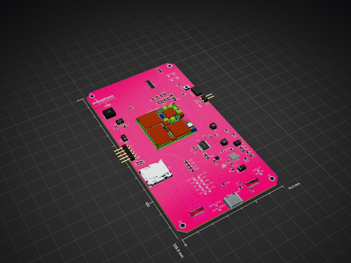
Pulsephone main board is an open-source printed circuit board by pulseopen, from the pulseopen/PulsePhone repository on GitHub, published under the GPL-3.0 licence. It is a 4-layer board of 70.5 × 128.5 mm with 94 parts on 217 nets, routed with 1,829 tracks and 322 vias.
It is built around the XL1509-3.3 and TP4056-42-ESOP8. Its parts include 38 capacitors, 11 resistors, 6 connectors, 5 ICs and 3 diodes. It belongs with the computers and single-board computers boards of this library.

A modular, open-source smartphone built for repairability, upgradability, and hardware freedom.
Built around the MCM-iMX93 System-on-Module, PulsePhone uses Hirose DF40 board-to-board connectors across all subsystems — keeping modules isolated, swappable, and independently developable.
The Main Board is the hub of the system, hosting the MCM-iMX93 SoM, an onboard DAC, and all signal routing. Every peripheral connects to it via DF40 connectors.
| Module | Interface | Role |
|---|---|---|
| Main Board | DF40 (host) | MCM-iMX93 SoM, DAC, signal routing |
| Display Module | MIPI/LVDS + Touch | Adapter for wide MIPI-DSI display compatability. |
| Camera Module | MIPI CSI-2 | Adapter for wide MIPI-CSI camera compatability. |
| Audio Module | Analog | Amp, speaker, headphone, mic |
Full connector pinout in MBI-Lite Specification.
First prototype! Revamping design. PCB Design in final polishing and bug fix stages!
Deffered to embedded inclusion on main board.
PCB Design DONE! This module acts like an adapter, so PulsePhone can have a wide range of MIPI-DSI displays to be compatible with.
Design TBD
Design Started
Planned inclusion. This extension will include an additional DF40 on the main board for community mods to the phone, like additional features.
Hardware released under GNU GPL-V3.0.
| Qty | Value | Footprint | References |
|---|---|---|---|
| 28 | 22uF | Capacitor_SMD:C_0805_2012Metric | C1, C10, C11, C14, C15, C16, C17, C18, C19, C20, C21, C22, C23, C24, C25, C26 +12 |
| 16 | TestPoint | TestPoint:TestPoint_Pad_D1.0mm | 3.3V1, 5V1, CLK-N1, CLK-P1, D0-N1, D0-P1, D1-N1, D1-P1, D2-N1, D2-P1, D3-N1, D3-P1, GND1, I2C3-SCL1, I2C3-SDA1, VBAT1 |
| 7 | 10uF | Capacitor_SMD:C_0603_1608Metric | C2, C3, C6, C12, C13, C33, C34 |
| 4 | MountingHole | MountingHole:MountingHole_2.2mm_M2_DIN965_Pad | H1, H2, H3, H4 |
| 3 | Conn_2Rows-35Pins_MountingPin | DF40-34P:HIROSE_DF40C-34DS-0.4V_58_ | J3, J4, J5 |
| 2 | 10 kΩ | Resistor_SMD:R_0805_2012Metric | R5, R6 |
| 2 | 2.2uF | Capacitor_SMD:C_0603_1608Metric | C4, C5 |
| 2 | 5.1 kΩ | Resistor_SMD:R_0805_2012Metric | R2, R3 |
| 2 | D_Schottky | Diode_SMD:D_SMA | D1, D4 |
| 2 | LOGO | LOGO | G***, G*** |
| 2 | TestPoint | TestPoint:TestPoint_Pad_1.0x1.0mm | AUD-L1, AUD-R1 |
| 1 | 1 MΩ | Resistor_SMD:R_0805_2012Metric | R10 |
| 1 | 1.1 MΩ | Resistor_SMD:R_0805_2012Metric | R7 |
| 1 | 1.2 kΩ | Resistor_SMD:R_0805_2012Metric | R4 |
| 1 | 1.5uH | Inductor_SMD_Wurth:L_Wurth_WE-LQSH-4020 | L3 |
| 1 | 100nF | Capacitor_SMD:C_0603_1608Metric | C43 |
| 1 | 174 kΩ | Resistor_SMD:R_0805_2012Metric | R9 |
| 1 | 1Mega Ohm | Resistor_SMD:R_0603_1608Metric_Pad0.98x0.95mm_HandSolder | R1 |
| 1 | 1kΩ | Resistor_SMD:R_0805_2012Metric | R8 |
| 1 | 1uH | Inductor_SMD_Wurth:L_Wurth_WE-LQSH-4020 | L2 |
| 1 | 47uh | Inductor_SMD:L_KOHERelec_MDA7030 | L1 |
| 1 | 51 kΩ | Resistor_SMD:R_0805_2012Metric | R11 |
| 1 | Battery | Connector_PinHeader_2.54mm:PinHeader_1x02_P2.54mm_Horizontal | BT1 |
| 1 | Conn_01x05 | Connector_PinHeader_2.54mm:PinHeader_1x05_P2.54mm_Horizontal | J2 |
| 1 | LED | LED_SMD:LED_0805_2012Metric | D5 |
| 1 | MCM93_MOD | mcm-imx93_footprint:LGA-140-080-30x30-iMX93 | MCM93_MOD1 |
| 1 | Micro_SD_Card_Det1 | Connector_Card:microSD_HC_Hirose_DM3AT-SF-PEJM5 | J7 |
| 1 | PCM5102APWR | PCM5102-DAC:SOP65P640X120-20N | U2 |
| 1 | SW_Push | Button_Switch_SMD:SW_Push_1P1T-SH_NO_CK_KMR2xxG | RESET1 |
| 1 | SW_Push | SSSS810701:SSSS810701 | ON/OFF1 |
| 1 | TP4056-42-ESOP8 | Package_SO:SOIC-8-1EP_3.9x4.9mm_P1.27mm_EP2.41x3.3mm_ThermalVias | U5 |
| 1 | TPS63020DSJR/3.7V Reg | TPS63020:IC_TPS63020DSJR | U4 |
| 1 | USB_C_Receptacle_USB2.0_14P | Connector_USB:USB_C_Receptacle_HRO_TYPE-C-31-M-12 | J1 |
| 1 | XL1509-3.3 | Package_SO:SOIC-8_3.9x4.9mm_P1.27mm | U1 |
| 1 | ~ | MIC2877-5.0YFT-TR:VREG_MIC2877-AYFT-TR | U3 |
pulseopen/PulsePhone
An almost fully modular open source phone running off of the DART-MX8M-MINI SoM.

Phila-H-23/kicad-project
This repository contains the KiCad design files, documentation, and resources for the power subsystem of a Micromouse robot developed as part of the EEE3088F course at the University of Cape Town.


evezor/tobor_v00
Tobor (robot spelled backwards), was built to be the most versatile open-source robotics system

AllYarnsAreBeautiful/ayab-hardware
Contains the schematics and layouts for the AYAB Arduino shield

MarkJB/ESP32_Plotter_Controller
An ESP32/TMC2130 based 2 axis controller designed for pen plotters

hatlabs/HALMET-hardware
Hat Labs Marine Engine & Tank interface hardware design files


It measures 70.5 × 128.5 mm and has 4 copper layers, 1.58 mm thick.
94 parts, built around the XL1509-3.3 and TP4056-42-ESOP8. The full list of its parts is on this page, with links to each part's symbol and footprint where PCBKit's library has them.
From the pulseopen/PulsePhone repository on GitHub, at the commit this page was made from: the board is main_board/pulsephone_main_board.kicad_pcb and its schematic audio/audio.kicad_sch. PCBKit opens the board in the browser, with nothing to install.
Its repository publishes it under the GPL-3.0 licence: you may reuse it on that licence's terms (keep the author's notice, and for a copyleft licence share your changes alike).