2 layers74.4 × 51.2 mm
Esp32-wroom timer
AlessandroAU/Chorus32-ESP32LapTimer
This is an ESP32 port of the popular Chorus RF Laptimer
66 parts102GPL-3.0
 PropNuts/wizardtracker-hardware13
A RSSI-based lap timer for drone racing.
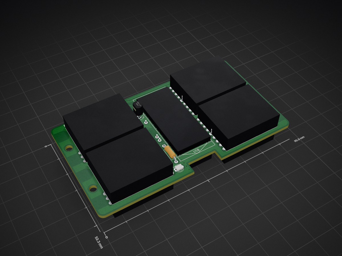
WizardView is an open-source printed circuit board by PropNuts, from the PropNuts/wizardtracker-hardware repository on GitHub, published under the MIT licence. It is a 2-layer board of 95.9 × 53.3 mm with 80 parts on 61 nets, routed with 283 tracks and 19 vias.
It is built around the RX5808. Its parts include 3 resistors, 3 connectors, 2 diodes and 1 IC. It belongs with the AVR (ATmega, ATtiny) boards of this library.
This project has moved to GitLab: https://gitlab.com/PropNuts/wizardtracker-hardware
There will be no further updates here.
This project contains the hardware and firmware for the PropNuts WizardTracker, an RSSI-based lap timer for drone racing.
The KiCad files can be found under hardware/.

The current revision (v2) allows for a total of either eight receivers, or six receivers with voltage and temperature monitoring. A voltage regulator and XT60 are mounted onboard to provide power.

You can put together a full system for around ~£65.
These are affiliate links.
firmware/firmware.ino.Config.h to your needs.On boot, the firmware opens serial at 250000bps. After a short delay, it will
begin sending RSSI values for each module, seperated by a space, ending in a new
line. Each line is prefixd with r .
In calibrated output mode, values range between 0 to 255. In raw output
mode (default), values range between 0 to 1023.
< r 110 220 150 243 135 254
< r 140 231 143 192 148 244
... etc
If enabled, voltage and temperature values will be sent periodically. Voltage
is prefixed with v and temperature is prefixed with t .
< v 16.08
< t 56.33
... etcThe command parser is extremely niave, with little to no error checking. Expect strange results with malformed commands. All command should end in a new line character.
Frequencies can be set by sending f <index> <frequency>. These frequencies
will be saved and reloaded on startup.
> f 0 5745
< ok
> f 1 5975
< ok
... etc
Modules can be calibrated using n (minimum) and m (maximum). These
calibration values will be saved and reloaded on startup. The device must be
rebooted for calibration to take effect.
[all modules set to same frequency]
[transmitter powered down]
> n
< ok
[transmitter powered up]
> m
< ok
Output can be toggled between raw output using r, and calibration output
using s. The default mode is raw output. This setting is saved and will be
reloaded on startup.
> r
< ok
< r 395 345 299 405 514 445
< ... etc
> s
< ok
< r 0 5 8 1 10 13
< ... etc
Information about the device can be requested using ?. The device will respond
in the format ? <module count> <frequency 1>...<frequency n> <raw mode>.
> ?
< ? 6 5695 5695 5695 5695 5695 5695 1
[6 receivers all on 5695MHz, with raw mode enabled]
< okThe source code for this project is based on my rx5808-pro-diversity rewrite.
This project is licensed under the terms of the MIT license.
| Qty | Value | Footprint | References |
|---|---|---|---|
| 8 | RX5808 | RX5808:RX5808 | RX1, RX2, RX3, RX4, RX5, RX6, RX7, RX8 |
| 4 | Mounting_Holes:MountingHole_3.2mm_M3 | , , , | |
| 2 | GS3 | Connectors:GS3 | J2, J3 |
| 1 | 100k | Resistors_THT:R_Axial_DIN0207_L6.3mm_D2.5mm_P10.16mm_Horizontal | R2 |
| 1 | 10k | Resistors_THT:R_Axial_DIN0207_L6.3mm_D2.5mm_P10.16mm_Horizontal | R3 |
| 1 | 330 | Resistors_THT:R_Axial_DIN0207_L6.3mm_D2.5mm_P10.16mm_Horizontal | R1 |
| 1 | 5VRegulator | RX5808:5VBEC | REG1 |
| 1 | ArduinoNano | RX5808:ArduinoNano | NANO1 |
| 1 | CONN_01X02 | RX5808:XT60_5V | J1 |
| 1 | D_Schottky | Diodes_THT:D_DO-41_SOD81_P10.16mm_Horizontal | D2 |
| 1 | LED | LEDs:LED_D3.0mm | D1 |
| 1 | LM35-LP | TO_SOT_Packages_THT:TO-92_Inline_Narrow_Oval | U1 |
| 1 | LOGO | RX5808:LOGO | G*** |
The 24 most common of 80 parts.
It measures 95.9 × 53.3 mm and has 2 copper layers, 1.6 mm thick.
80 parts, built around the RX5808. The full list of its parts is on this page, with links to each part's symbol and footprint where PCBKit's library has them.
From the PropNuts/wizardtracker-hardware repository on GitHub, at the commit this page was made from: the board is hardware/WizardView.kicad_pcb. PCBKit opens the board in the browser, with nothing to install.
Its repository publishes it under the MIT licence: you may reuse it on that licence's terms (keep the author's notice, and for a copyleft licence share your changes alike).
AlessandroAU/Chorus32-ESP32LapTimer
This is an ESP32 port of the popular Chorus RF Laptimer


msaribekyan/rx5808-receiver
RX5808 based 5.8 GHz analog video receiver module


Eddie00000/Q2Montage_et_realisation-VRX_MODULE
KiCad project files
