Skip to the content
PCBKitNew board
2 layers83.8 × 91.4 mmHIDControls, the printed circuit board in 3D

A customizable HID USB device with buttons, encoders, sliders, potentiometers, etc.

Size
83.8 × 91.4 mm
Copper layers
2
Thickness
1.6 mm
Parts
65
Nets
81
Pads
310
Tracks, vias
427, 9
Pours
9
Routed
Yes
KiCad
KiCad 6 (file 20211014)
Created
20 Feb 2023
Updated
19 Jun 2023

Overview

HIDControls is an open-source printed circuit board by profdc9, from the profdc9/HIDPanel repository on GitHub. It is a 2-layer board of 83.8 × 91.4 mm with 65 parts on 81 nets, routed with 427 tracks and 9 vias.

Its parts include 21 capacitors, 17 resistors, 12 switches and 1 connector.

README

README.md

HIDPanel

This is a customizable HID controller for game panels. The HIDPanel has positions for up to 15 plug in control modules. These modules can be single buttons, button pairs, rotary encoders, rotary potentiometers, slide potentiometers, and dual axis joysticks (PS4 or Xbox One type replacement joysticks).

The device appears as a USB CDC serial port, a USB HID keyboard, and a USB HID gamepad. The actions of each module is configured through the serial port. A command string configures the Keyboard or Gamepad controls to be triggered in response to each action.

Commands

The commands are sent via the USB CDC serial port terminated by the enter character. Here are the commands:

SET <module number> <action number> <action command string>

Sets the action command string corresponding to the action number for the given module number (1 to 15).

SHOW <module number>

Shows the current command strings for the module number. If the module number is zero, show the action strings for all of the modules.

WRITE

Writes the current configuration to flash memory to be restored on power up.

HELP

Display the help (the list of commands).

Module inputs

Each module has three inputs. Switch 1, which is a digital only input, switch 2, which is digital or analog, and an analog input, which can be used as a digital or analog input.

The action numbers are:

  • 100: Button 1 Pressed (grounded)
  • 101: Button 1 Released (high)
  • 200: Button 2 Pressed (grounded)
  • 201: Button 2 Released (high)
  • 300: Analog axis pressed (grounded)
  • 301: Analog axis released (high)
  • 302: Analog axis moved
  • 311: Analog axis position 1/9 (left most)
  • 312: Analog axis position 2/9
  • 313: Analog axis position 3/9
  • 314: Analog axis position 4/9
  • 315: Analog axis position 5/9 (center)
  • 316: Analog axis position 6/9
  • 317: Analog axis position 7/9
  • 318: Analog axis position 8/9
  • 319: Analog axis position 9/9 (right most)
  • 400: Rotary encoder left
  • 401: Rotary encoder right

Command string

The command string is a sequence of one or two character codes separated by commas. It should not contain any spaces. There are three modes. The mode needs to be selected before the commands for the mode are used. Multiple modes may be used in the command string by switching between them. The default is keyboard mode.

  • LD: LED Mode
    • Hx: Turn on LED x (x = 1 to 4)
    • Lx: Turn off LED x (x = 1 to 4)
  • GP: Gamepad Mode
    • Gx: Set axis x to analog input (x = 1-6, 1=left stick x, 2=left stick y, 3=left stick z, 4=right stick x, 5=right stick y, 6=right stick z)
    • Nx: Set axis x to analog input but reverse the axis
    • Zx: Set axis x to switch 2 analog input
    • Yx: Set axis x to switch 2 analog input but reverse the axis
    • Dx: Set Dpad input to value x (x = 0-8, 0=Centered, 1=Up, 2=Up Right, 3=Right, 4=Down Right, 5=Down, 6=Down Left, 7=Left, 8=Up Left)
    • Hx: Press button x (x=1 to 32)
    • Lx: Release button x
  • KB: Keyboard Mode
    • Blank (zero length): keyboard release (two consective commas).
    • LC: Select left control for next key
    • LS: Select left shift for next key
    • LA: Select left alt for next key
    • LG: Select left gui for next key
    • RC: Select right control for next key
    • RS: Select right shift for next key
    • RA: Select right alt for next key
    • RG: Select right gui for next key
    • NK: No key
    • A-Z: Press key A to Z
    • 0-9: Press key 0 to 9
    • EN: Enter
    • ES: Escape
    • BK: Backspace
    • TB: Tab
    • SP: Space bar
    • -: Minus key
    • =: Equal key
    • [: Left bracket
    • ]: Right bracket
    • \: Backslash
    • E1: Europe 1
    • E2: Europe 2
    • ; : Semicolon
    • ` : Grave
    • CM: Comma
    • .: Period
    • /: Slash
    • CC: Caps Lock
    • F1-F9: F1 to F9
    • FA: F10 key
    • FB: F11 key
    • FC: F12 Key
    • PS: Print Screen
    • SL: Scroll Lock
    • PA: Pause
    • IN: Insert
    • HO: Home
    • PU: Page Up
    • DE: Delete
    • ED: End
    • PD: Page Down
    • AR: Arrow Right
    • AL: Arrow Left
    • AD: Arrow Down
    • AU: Arrow Up
    • NL: Num Lock
    • KD: Keypad Divide
    • KM: Keypad Multiple
    • KS: Keypad Subtract
    • KA: Keypad Add
    • KE: Keypad Enter
    • K0-K9: Keypad 0 to 9
    • KL: Keypad Decimal Point
    • KQ: Keypad Equal

Examples:

  • KB,LS,H,,E,,L,,L,,O,, : Type the word "HELLO" with the left shift key pressed down during "H" (to capitalize it).
  • GP,G2 : Take the analog value of the module and set it to the left stick Y axis.
  • GP,D1,D0,D1,D0,D5,D0,D5,D0,D7,D0,D3,D0,D3,D0,H2,L2,H1,L1 : Do combination up,up,down,down,left,right,left,right (on DPad), and then press and release button 2 and then button 1.
  • GP,H1,LD,H2 : press button 1, light up LED 2
  • KB,F1,GP,H1,LD,L3,GP,L1 : Press keyboard key F1, press button 1 on gamepad, turn off LED 3, release button 1 on gamepad. Button F1 remains pressed.

Complete commands:

  • SET 1 100 KB,A,, : when button 1 on module 1 is pressed, press down the A key
  • SET 1 101 KB,, : when button 1 on module 1 is release, release any key
  • SET 11 302 GP,G1 : set analog axis of module 11 to axis 1 of the gamepad
  • SET 15 302 GP,G2 : set analog axis of module 15 to axis 2 of the gamepad
  • SET 11 302 GP,N1 : set analog axis of module 11 to axis 1 of the gamepad, but invert the input
  • SET 15 302 GP,N2 : set analog axis of module 15 to axis 2 of the gamepad, but invert the input
  • SET 11 100,GP,H4 : when analog stick button is pushed in, press button 4 on gamepad
  • SET 11 101,GP,L4 : when analog stick button is released, depress button 4 on gamepad

Pictures:

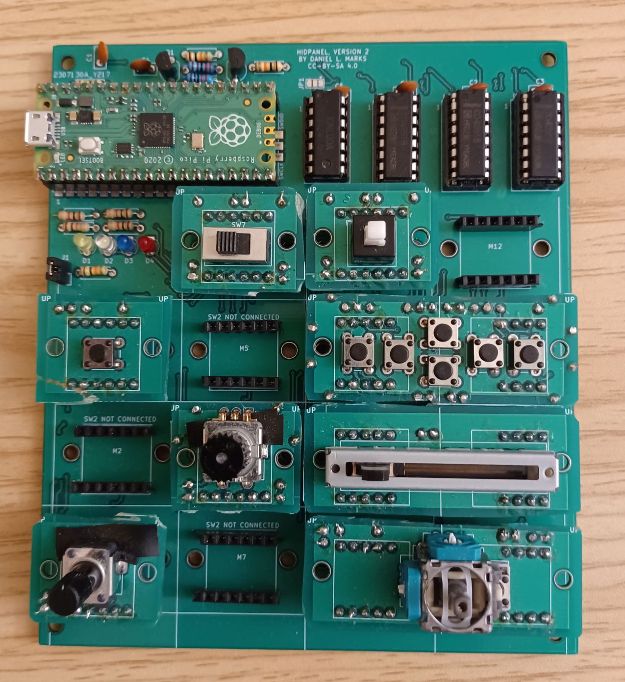
The following is a pciture of the HIDPanel with different controls in it. In module 1 is a single push button. In module 3 is a rotary potentiometer, In module 4 is a slide switch. In module 6 is a rotary encoder. In module 8 is a push-on push-off button. Modules 9 and 13 have a digital gamepad. Modules 10 and 14 have a slide potentiometer. Modules 11 and 15 have a dual axis joystick.

HIDPanel

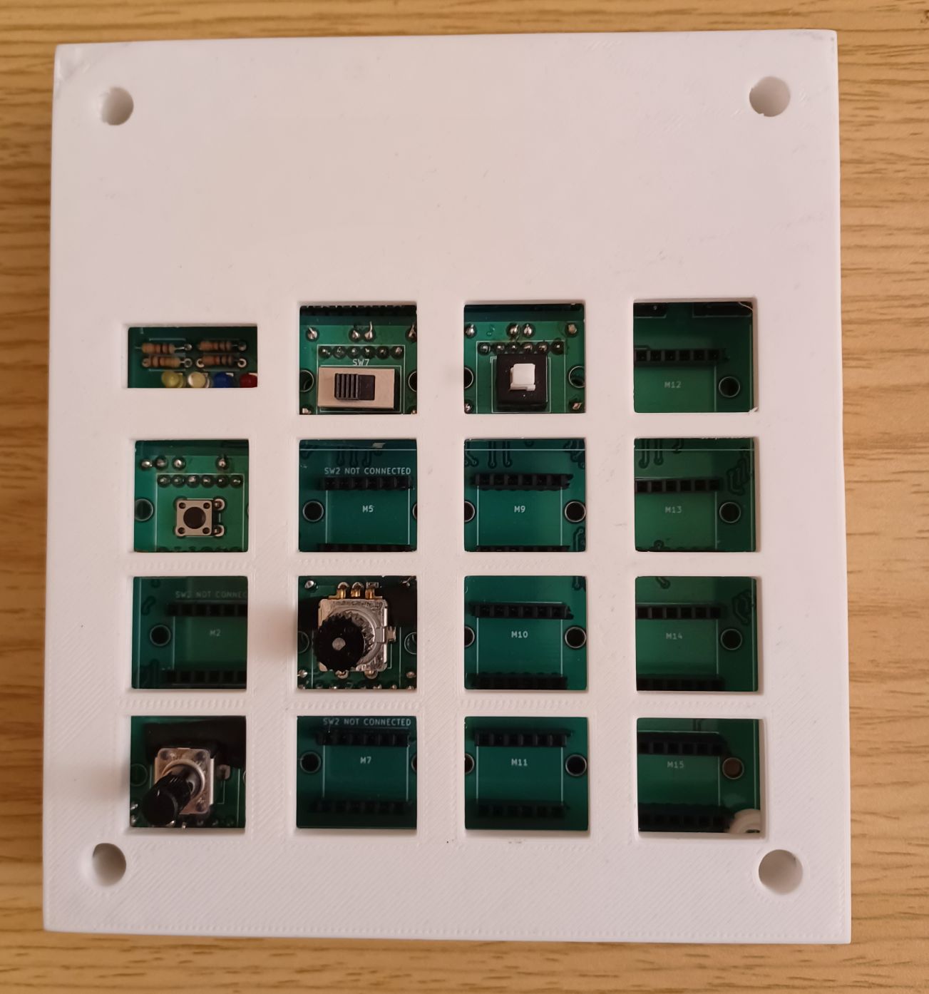
This is the 3-d printed cover that goes over the HIDPanel. It is a parametric FreeCAD model and the port openings can be customized in FreeCAD before outputting the cover for the particular modules used.

Cover

Parts

65
QtyValueFootprintReferences
21100 nFCapacitor_THT:C_Disc_D5.0mm_W2.5mm_P2.50mmC1, C2, C3, C4, C10, C12, C13, C14, C15, C16, C17, C18, C19, C20, C21, C22 +5
1710kResistor_THT:R_Axial_DIN0207_L6.3mm_D2.5mm_P7.62mm_HorizontalR1, R2, R3, R7, R8, R10, R11, R12, R13, R14, R15, R16, R17, R18, R19, R20 +1
86mm Button_Switch_THT:SW_PUSH_6mmSW2, SW8, SW9, SW10, SW11, SW12, SW13, SW14
6ModulePlugHIDControls:ModulePlugM1, M3, M4, M7, M8, M11
3ModulePlugHIDControls:RightPartModulePlugM9, M10, M12
3ModulePlugHIDControls:LeftPartModulePlugM2, M5, M6
12031N HIDControls:Linear-Pot-2031NRV2
15mm TOGGLE, SS12D10HIDControls:5mmSPDTtoggleSW7
16mmButton_Switch_THT:SW_PUSH_6mmSW1
18x8 SWITCHButton_Switch_THT:SW_Push_2P2T_Toggle_CK_PVA2xxH1xxxxxxV2SW6
1ALPS EC11Rotary_Encoder:RotaryEncoder_Alps_EC11E-Switch_Vertical_H20mmSW5
1ALPS RK09KPotentiometer_THT:Potentiometer_Alps_RK09K_Single_VerticalRV1
1AnalogJoystickHIDControls:AnalogJoystickJ1

Questions

How big is the HIDControls PCB?

It measures 83.8 × 91.4 mm and has 2 copper layers, 1.6 mm thick.

What parts does the HIDControls use?

65 parts. The full list of its parts is on this page, with links to each part's symbol and footprint where PCBKit's library has them.

Where can I download the HIDControls KiCad files?

From the profdc9/HIDPanel repository on GitHub, at the commit this page was made from: the board is HIDControls/HIDControls.kicad_pcb and its schematic HIDControls/HIDControls.kicad_sch. PCBKit opens the board in the browser, with nothing to install.

Can I use the HIDControls design in my own project?

Its repository states no licence, so its author keeps all rights: ask profdc9 before reusing the design.

More from profdc9/HIDPanel

1
  • 2 layers116.8 × 134.6 mmHIDPanel, the printed circuit board in 3D

    HIDPanel

    profdc9/HIDPanel

    A customizable HID USB device with buttons, encoders, sliders, potentiometers, etc.

    48 parts48

Similar boards

  • 2 layers42 × 67 mmLalboard, the printed circuit board in 3D

    Lalboard

    JesusFreke/lalboard

    A 3D-printed keyboard inspired by the DataHand

    65 parts993
  • 2 layers198.1 × 30.5 mmSplitflap driver, the printed circuit board in 3D

    Splitflap driver

    drandyhaas/KiCadRoutingTools

    A set of Python/Rust tools to aid routing in KiCad

    65 parts744MIT
  • 2 layers74.8 × 32.5 mmMooltipass mini, the printed circuit board in 3D

    Mooltipass mini

    limpkin/mooltipass

    Github repository dedicated to the mooltipass project

    65 parts531
  • 2 layers60 × 100 mmV3 Connector Only, the printed circuit board in 3D

    V3 Connector Only

    PiTracLM/PiTrac

    Launch monitor using low-cost raspberry pi and camera hardware to determine ball launch speed, angles and spin. See https://discord.gg/vGuyAAxXJH (permalink)

    65 parts439GPL-2.0
  • 2 layers45 × 58.2 mmOpentama, the printed circuit board in 3D

    Opentama

    Sparkr-tech/opentama

    An open-source reference design for MCUGotchi

    65 parts237
  • 2 layers40 × 120 mmPhotodiode board v3, the printed circuit board in 3D

    Photodiode board v3

    0x23/nmWave-Interferometer

    An Open Source Interferometer for Accurate Distance Measurements

    65 parts151MIT
  • 2 layers78 × 130 mmLofence, the printed circuit board in 3D

    Lofence

    kiu/lofence

    LoFence is a LoRaWAN capable IoT electric fence monitoring system running on the The Things Network.

    65 parts142MIT