Skip to the content
PCBKitNew board
2 layers116.8 × 134.6 mmHIDPanel, the printed circuit board in 3D

A customizable HID USB device with buttons, encoders, sliders, potentiometers, etc.

Size
116.8 × 134.6 mm
Copper layers
2
Thickness
1.6 mm
Parts
48
Nets
106
Pads
417
Tracks, vias
1,358, 177
Pours
1
Routed
Yes
KiCad
KiCad 6 (file 20211014)
Created
20 Feb 2023
Updated
19 Jun 2023

Overview

HIDPanel is an open-source printed circuit board by profdc9, from the profdc9/HIDPanel repository on GitHub. It is a 2-layer board of 116.8 × 134.6 mm with 48 parts on 106 nets, routed with 1,358 tracks and 177 vias.

It is built around the 74HCT00D. Its parts include 10 resistors, 6 capacitors, 6 ICs, 4 diodes and 1 transistor. It belongs with the RP2040 boards of this library.

Main components

1

README

README.md

HIDPanel

This is a customizable HID controller for game panels. The HIDPanel has positions for up to 15 plug in control modules. These modules can be single buttons, button pairs, rotary encoders, rotary potentiometers, slide potentiometers, and dual axis joysticks (PS4 or Xbox One type replacement joysticks).

The device appears as a USB CDC serial port, a USB HID keyboard, and a USB HID gamepad. The actions of each module is configured through the serial port. A command string configures the Keyboard or Gamepad controls to be triggered in response to each action.

Commands

The commands are sent via the USB CDC serial port terminated by the enter character. Here are the commands:

SET <module number> <action number> <action command string>

Sets the action command string corresponding to the action number for the given module number (1 to 15).

SHOW <module number>

Shows the current command strings for the module number. If the module number is zero, show the action strings for all of the modules.

WRITE

Writes the current configuration to flash memory to be restored on power up.

HELP

Display the help (the list of commands).

Module inputs

Each module has three inputs. Switch 1, which is a digital only input, switch 2, which is digital or analog, and an analog input, which can be used as a digital or analog input.

The action numbers are:

  • 100: Button 1 Pressed (grounded)
  • 101: Button 1 Released (high)
  • 200: Button 2 Pressed (grounded)
  • 201: Button 2 Released (high)
  • 300: Analog axis pressed (grounded)
  • 301: Analog axis released (high)
  • 302: Analog axis moved
  • 311: Analog axis position 1/9 (left most)
  • 312: Analog axis position 2/9
  • 313: Analog axis position 3/9
  • 314: Analog axis position 4/9
  • 315: Analog axis position 5/9 (center)
  • 316: Analog axis position 6/9
  • 317: Analog axis position 7/9
  • 318: Analog axis position 8/9
  • 319: Analog axis position 9/9 (right most)
  • 400: Rotary encoder left
  • 401: Rotary encoder right

Command string

The command string is a sequence of one or two character codes separated by commas. It should not contain any spaces. There are three modes. The mode needs to be selected before the commands for the mode are used. Multiple modes may be used in the command string by switching between them. The default is keyboard mode.

  • LD: LED Mode
    • Hx: Turn on LED x (x = 1 to 4)
    • Lx: Turn off LED x (x = 1 to 4)
  • GP: Gamepad Mode
    • Gx: Set axis x to analog input (x = 1-6, 1=left stick x, 2=left stick y, 3=left stick z, 4=right stick x, 5=right stick y, 6=right stick z)
    • Nx: Set axis x to analog input but reverse the axis
    • Zx: Set axis x to switch 2 analog input
    • Yx: Set axis x to switch 2 analog input but reverse the axis
    • Dx: Set Dpad input to value x (x = 0-8, 0=Centered, 1=Up, 2=Up Right, 3=Right, 4=Down Right, 5=Down, 6=Down Left, 7=Left, 8=Up Left)
    • Hx: Press button x (x=1 to 32)
    • Lx: Release button x
  • KB: Keyboard Mode
    • Blank (zero length): keyboard release (two consective commas).
    • LC: Select left control for next key
    • LS: Select left shift for next key
    • LA: Select left alt for next key
    • LG: Select left gui for next key
    • RC: Select right control for next key
    • RS: Select right shift for next key
    • RA: Select right alt for next key
    • RG: Select right gui for next key
    • NK: No key
    • A-Z: Press key A to Z
    • 0-9: Press key 0 to 9
    • EN: Enter
    • ES: Escape
    • BK: Backspace
    • TB: Tab
    • SP: Space bar
    • -: Minus key
    • =: Equal key
    • [: Left bracket
    • ]: Right bracket
    • \: Backslash
    • E1: Europe 1
    • E2: Europe 2
    • ; : Semicolon
    • ` : Grave
    • CM: Comma
    • .: Period
    • /: Slash
    • CC: Caps Lock
    • F1-F9: F1 to F9
    • FA: F10 key
    • FB: F11 key
    • FC: F12 Key
    • PS: Print Screen
    • SL: Scroll Lock
    • PA: Pause
    • IN: Insert
    • HO: Home
    • PU: Page Up
    • DE: Delete
    • ED: End
    • PD: Page Down
    • AR: Arrow Right
    • AL: Arrow Left
    • AD: Arrow Down
    • AU: Arrow Up
    • NL: Num Lock
    • KD: Keypad Divide
    • KM: Keypad Multiple
    • KS: Keypad Subtract
    • KA: Keypad Add
    • KE: Keypad Enter
    • K0-K9: Keypad 0 to 9
    • KL: Keypad Decimal Point
    • KQ: Keypad Equal

Examples:

  • KB,LS,H,,E,,L,,L,,O,, : Type the word "HELLO" with the left shift key pressed down during "H" (to capitalize it).
  • GP,G2 : Take the analog value of the module and set it to the left stick Y axis.
  • GP,D1,D0,D1,D0,D5,D0,D5,D0,D7,D0,D3,D0,D3,D0,H2,L2,H1,L1 : Do combination up,up,down,down,left,right,left,right (on DPad), and then press and release button 2 and then button 1.
  • GP,H1,LD,H2 : press button 1, light up LED 2
  • KB,F1,GP,H1,LD,L3,GP,L1 : Press keyboard key F1, press button 1 on gamepad, turn off LED 3, release button 1 on gamepad. Button F1 remains pressed.

Complete commands:

  • SET 1 100 KB,A,, : when button 1 on module 1 is pressed, press down the A key
  • SET 1 101 KB,, : when button 1 on module 1 is release, release any key
  • SET 11 302 GP,G1 : set analog axis of module 11 to axis 1 of the gamepad
  • SET 15 302 GP,G2 : set analog axis of module 15 to axis 2 of the gamepad
  • SET 11 302 GP,N1 : set analog axis of module 11 to axis 1 of the gamepad, but invert the input
  • SET 15 302 GP,N2 : set analog axis of module 15 to axis 2 of the gamepad, but invert the input
  • SET 11 100,GP,H4 : when analog stick button is pushed in, press button 4 on gamepad
  • SET 11 101,GP,L4 : when analog stick button is released, depress button 4 on gamepad

Pictures:

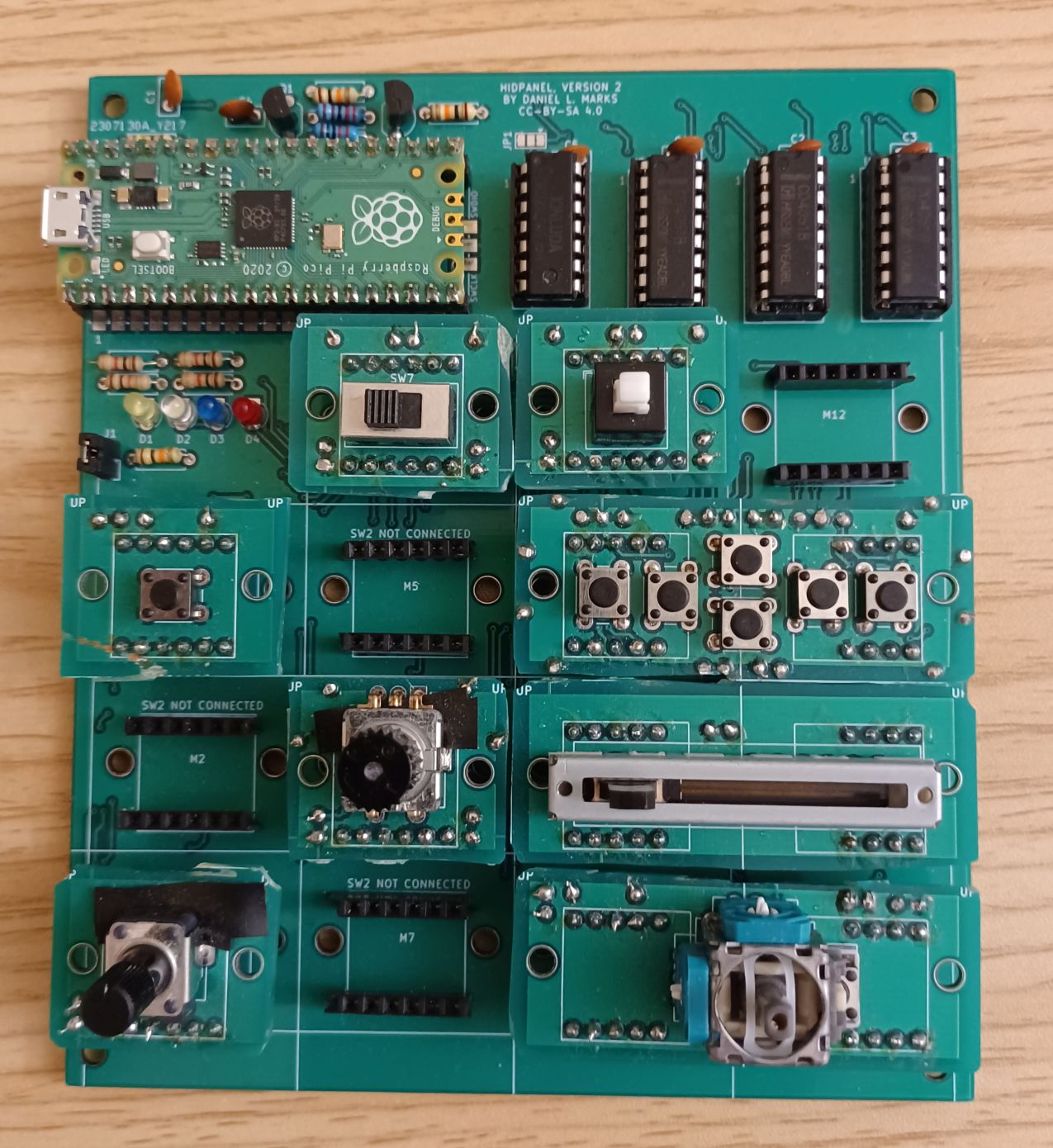
The following is a pciture of the HIDPanel with different controls in it. In module 1 is a single push button. In module 3 is a rotary potentiometer, In module 4 is a slide switch. In module 6 is a rotary encoder. In module 8 is a push-on push-off button. Modules 9 and 13 have a digital gamepad. Modules 10 and 14 have a slide potentiometer. Modules 11 and 15 have a dual axis joystick.

HIDPanel

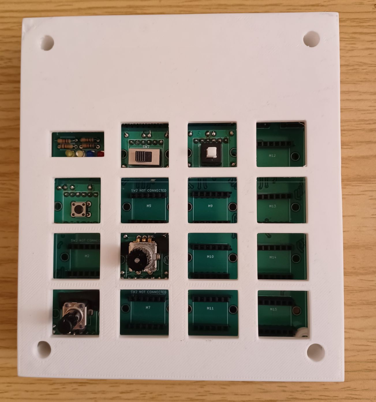
This is the 3-d printed cover that goes over the HIDPanel. It is a parametric FreeCAD model and the port openings can be customized in FreeCAD before outputting the cover for the particular modules used.

Cover

Parts

48
QtyValueFootprintReferences
15ModulePlugHIDPanel:ModulePlugM1, M2, M3, M4, M5, M6, M7, M8, M9, M10, M11, M12, M13, M14, M15
6100 nFCapacitor_THT:C_Disc_D5.0mm_W2.5mm_P2.50mmC1, C2, C3, C4, C5, C6
410kResistor_THT:R_Axial_DIN0207_L6.3mm_D2.5mm_P7.62mm_HorizontalR5, R6, R7, R10
4220RResistor_THT:R_Axial_DIN0207_L6.3mm_D2.5mm_P7.62mm_HorizontalR1, R2, R3, R4
4LEDLED_THT:LED_D3.0mmD1, D2, D3, D4
4MountingHoleMountingHole:MountingHole_3.2mm_M3H1, H2, H3, H4
34051Package_DIP:DIP-16_W7.62mm_SocketU3, U4, U5
1150RResistor_THT:R_Axial_DIN0207_L6.3mm_D2.5mm_P7.62mm_HorizontalR8
12N3904Package_TO_SOT_THT:TO-92_Inline_WideQ1
12PosTerminalConnector_PinHeader_2.54mm:PinHeader_1x02_P2.54mm_VerticalJ1
12k2Resistor_THT:R_Axial_DIN0207_L6.3mm_D2.5mm_P7.62mm_HorizontalR9
174HCT00Package_DIP:DIP-14_W7.62mm_SocketU2
1Jumper_3_Bridged12Jumper:SolderJumper-3_P1.3mm_Bridged2Bar12_Pad1.0x1.5mmJP1
1PicoHIDPanel:RPi_Pico_SMD_THU1
1TL431LPPackage_TO_SOT_THT:TO-92_Inline_WideU6

Questions

How big is the HIDPanel PCB?

It measures 116.8 × 134.6 mm and has 2 copper layers, 1.6 mm thick.

What parts does the HIDPanel use?

48 parts, built around the 74HCT00D. The full list of its parts is on this page, with links to each part's symbol and footprint where PCBKit's library has them.

Where can I download the HIDPanel KiCad files?

From the profdc9/HIDPanel repository on GitHub, at the commit this page was made from: the board is HIDPanel/HIDPanel.kicad_pcb and its schematic HIDControls/HIDControls.kicad_sch. PCBKit opens the board in the browser, with nothing to install.

Can I use the HIDPanel design in my own project?

Its repository states no licence, so its author keeps all rights: ask profdc9 before reusing the design.

More from profdc9/HIDPanel

1
  • 2 layers83.8 × 91.4 mmHIDControls, the printed circuit board in 3D

    HIDControls

    profdc9/HIDPanel

    A customizable HID USB device with buttons, encoders, sliders, potentiometers, etc.

    65 parts48

Similar boards

  • 2 layers333.4 × 149.9 mmOmega Mainboard, the printed circuit board in 3D

    Omega Mainboard

    skiselev/omega

    Omega Home Computer

    248 parts459GPL-3.0
  • 2 layers297.2 × 180.3 mm8bit computer, the printed circuit board in 3D

    8bit computer

    vascofazza/8bit-cpu

    Schematics & code for my 74LS-based 8-bit MK1 CPU

    377 parts317MIT
  • 4 layers304.8 × 330.2 mm2000ATX, the printed circuit board in 3D

    2000ATX

    jasonsbeer/Amiga-2000-EATX

    An Amiga 2000 PCB in the EATX form factor.

    614 parts200GPL-3.0
  • 2 layers99.1 × 99.7 mmRC6502 General Video Adapter, the printed circuit board in 3D

    RC6502 General Video Adapter

    tebl/RC6502-Apple-1-Replica

    An expandable SBC-version of the Apple 1 computer, easy to get started with and lot of cool stuff that can be added to it!

    80 parts193GPL-3.0
  • 2 layers100 × 50 mmRc2014-ym2149, the printed circuit board in 3D

    Rc2014-ym2149

    electrified/rc2014-ym2149

    KiCad schematics and gerbers for a YM sound card for the RC2014. See it in action here: https://www.youtube.com/watch?v=-iLwi9FagFE

    37 parts78
  • 2 layers100 × 50 mmSN76489, the printed circuit board in 3D

    SN76489

    jblang/SN76489

    SN76489 Sound Card for RC2014

    23 parts52
  • 2 layers333.4 × 149.9 mmOmega Mainboard, the printed circuit board in 3D

    Omega Mainboard

    merlinkv/Omega_MSX2

    Update of the Omega Home Computer Project

    265 parts40GPL-3.0
  • 2 layers127 × 114.3 mmNes, the printed circuit board in 3D

    Nes

    dkonigsberg/nestronic

    Nestronic Game Music Synthesizer Alarm Clock

    144 parts38