2 layers96.5 × 55.2 mm

 vascofazza/8bit-cpu317
Schematics & code for my 74LS-based 8-bit MK1 CPU
8bit computer is an open-source printed circuit board by vascofazza, from the vascofazza/8bit-cpu repository on GitHub, published under the MIT licence. It is a 2-layer board of 297.2 × 180.3 mm with 377 parts on 574 nets, routed with 11,197 tracks and 441 vias.
It is built around the 74HCT245, 74HCT157D and 74HCT273D, with the 74HCT08D, 74HCT32D and 74LS157PC among its other parts. Its parts include 134 diodes, 81 ICs, 45 capacitors, 32 resistors and 7 switches. It belongs with the retro computing and games boards and the NXP (LPC, Kinetis, i.MX RT) boards of this library.


Schematics and code for my home-made 8-bit CPU and its companion boards.
Articles about this project:
During the past month, I designed and built a programmable 8-bit CPU from scratch, out of basic series 74LS logic ICs.
This repository contains pictures, schematics, and code for this project and its companion boards.
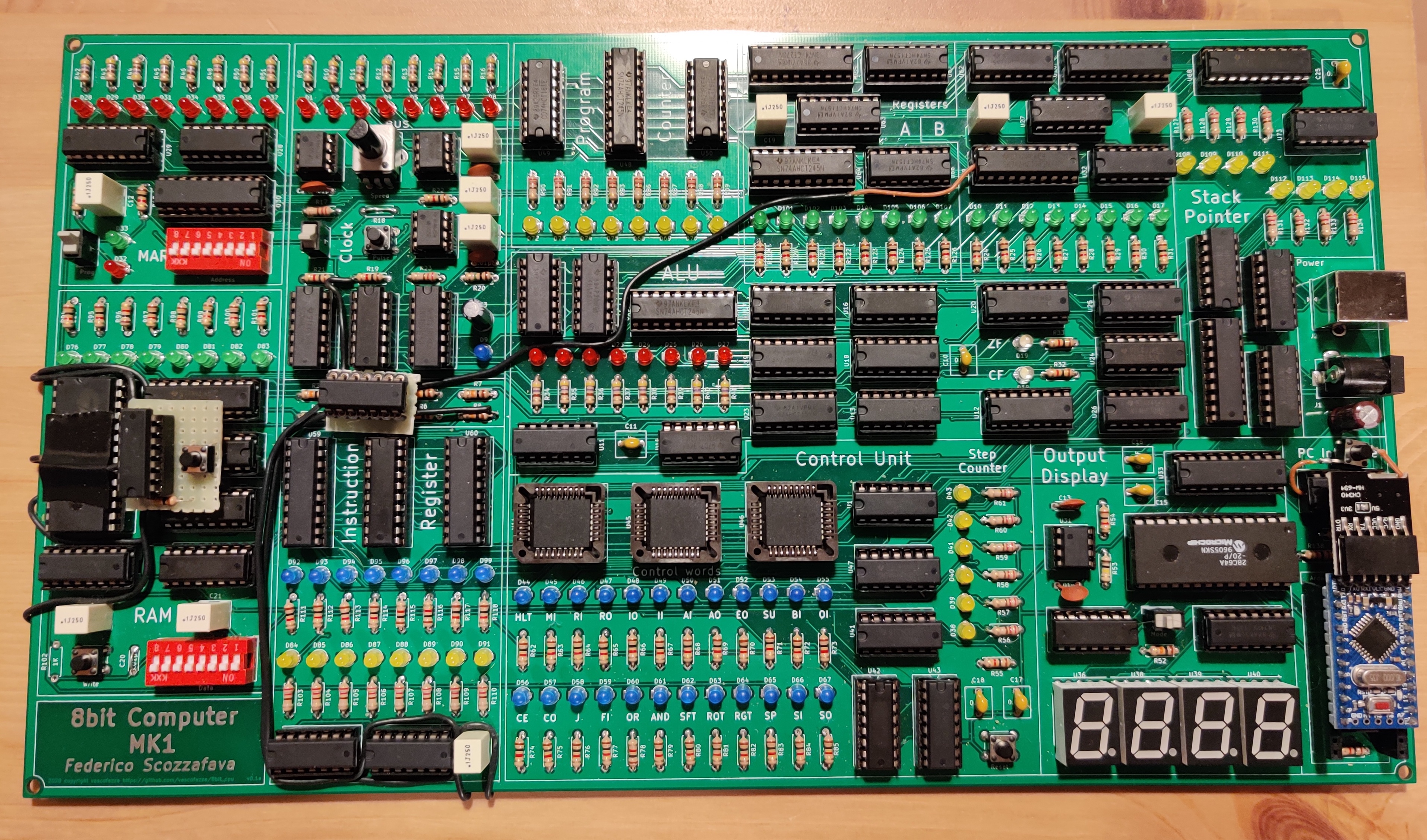
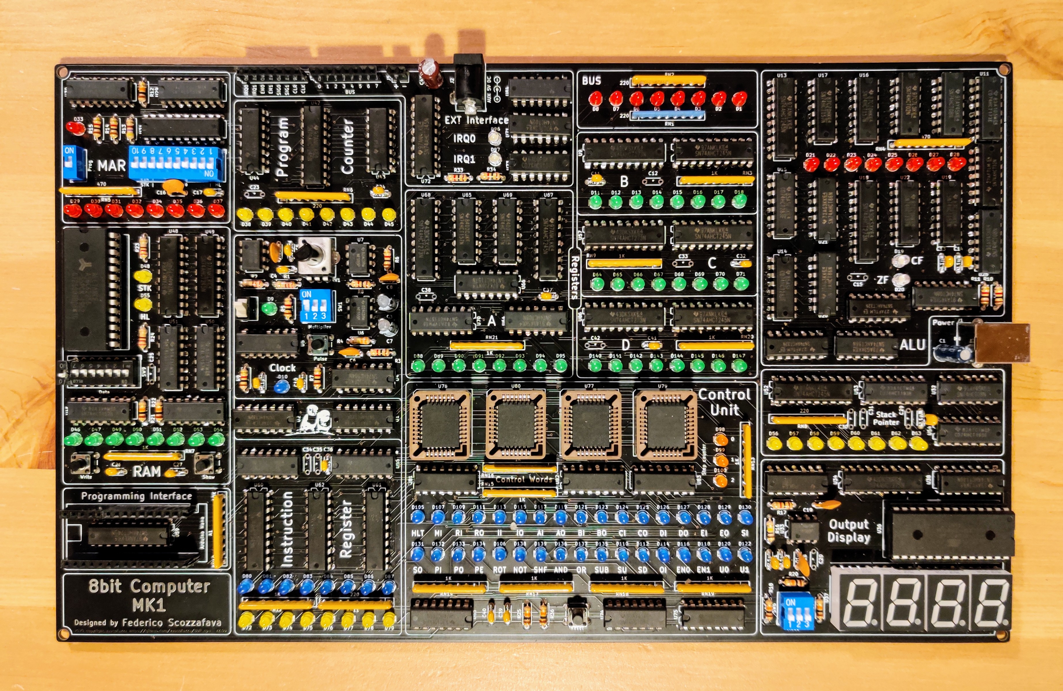
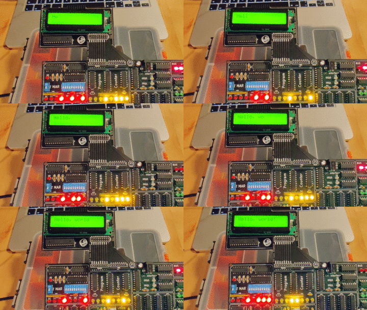
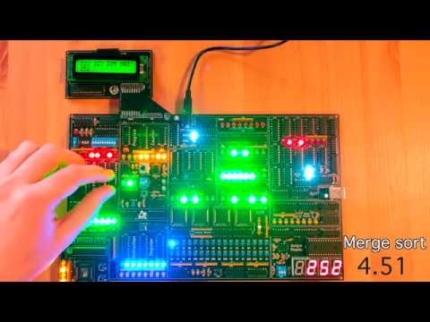
DEMO VIDEO (YouTube)
The MK1 CPU is composed of several modules, all connected trough a common 8-bit BUS, the status of each module is shown by dedicated LEDs.
A, B, C, D) and a stack pointer register for subroutine calls.CF) and zero (ZF) ALU flags.HL and STK address signals available in the MAR dip-switch.| Qty | Value | Footprint | References |
|---|---|---|---|
| 43 | BLUE | LED_THT:LED_D3.0mm | D10, D100, D101, D102, D103, D104, D105, D106, D107, D108, D109, D110, D111, D112, D113, D114 +27 |
| 41 | GREEN | LED_THT:LED_D3.0mm | D11, D12, D13, D14, D15, D16, D17, D18, D127, D128, D129, D130, D131, D132, D133, D134 +25 |
| 25 | RED | LED_THT:LED_D3.0mm | D1, D2, D3, D21, D22, D23, D24, D25, D26, D27, D28, D29, D30, D31, D32, D33 +9 |
| 21 | YELLOW | LED_THT:LED_D3.0mm | D38, D39, D40, D41, D42, D43, D44, D45, D48, D55, D56, D57, D58, D59, D60, D61 +5 |
| 19 | 0.1µF | Capacitor_THT:C_Disc_D4.3mm_W1.9mm_P5.00mm | C10, C11, C12, C14, C15, C18, C22, C23, C25, C28, C29, C30, C34, C36, C37, C40 +3 |
| 15 | 1K | Resistor_THT:R_Axial_DIN0207_L6.3mm_D2.5mm_P7.62mm_Horizontal | R3, R5, R6, R7, R8, R9, R10, R11, R14, R15, R17, R25, R26, R27, R28 |
| 14 | 1K | Resistor_THT:R_Array_SIP9 | RN3, RN7, RN9, RN10, RN11, RN12, RN13, RN14, RN15, RN16, RN17, RN18, RN19, RN20 |
| 11 | 74HCT245 | Package_DIP:DIP-20_W7.62mm | U8, U14, U42, U48, U49, U52, U56, U59, U65, U70, U80 |
| 10 | * | Capacitor_THT:C_Disc_D4.3mm_W1.9mm_P5.00mm | C13, C16, C21, C26, C31, C32, C33, C35, C38, C43 |
| 10 | 10K | Resistor_THT:R_Axial_DIN0207_L6.3mm_D2.5mm_P7.62mm_Horizontal | R12, R18, R19, R20, R21, R22, R29, R30, R31, R32 |
| 9 | 74HCT157 | Package_DIP:DIP-16_W7.62mm | U17, U18, U20, U23, U45, U62, U63, U67, U68 |
| 8 | 0.01µF | Capacitor_THT:C_Disc_D4.3mm_W1.9mm_P5.00mm | C3, C6, C7, C9, C19, C20, C39, C45 |
| 8 | 74HCT273 | Package_DIP:DIP-20_W7.62mm | U9, U19, U32, U34, U57, U61, U66, U81 |
| 7 | 74HCT08 | Package_DIP:DIP-14_W7.62mm | U5, U10, U26, U27, U29, U58, U64 |
| 5 | 74HCT32 | Package_DIP:DIP-14_W7.62mm | U1, U2, U12, U25, U28 |
| 4 | 220 | Resistor_THT:R_Axial_DIN0207_L6.3mm_D2.5mm_P7.62mm_Horizontal | R1, R2, R23, R24 |
| 4 | 74LS157 | Package_DIP:DIP-16_W7.62mm | U30, U31, U50, U51 |
| 4 | 7SEGMENT_CC | Display_7Segment:7SegmentLED_LTS6760_LTS6780 | U37, U39, U40, U41 |
| 4 | AM29F040 | Housings_LCC:PLCC-32_THT-Socket | U73, U74, U75, U76 |
| 4 | MountingHole_3.2mm_M3 | MountingHole:MountingHole_3.2mm_M3 | MH0, MH1, MH2, MH3 |
| 4 | NE555 | Package_DIP:DIP-8_W7.62mm | U3, U6, U7, U33 |
| 4 | WHITE | LED_THT:LED_D3.0mm | D19, D20, D88, D89 |
| 3 | 0.01µf | Capacitor_THT:C_Disc_D4.3mm_W1.9mm_P5.00mm | C24, C27, C44 |
| 3 | 470 | Resistor_THT:R_Array_SIP9 | RN2, RN4, RN5 |
| 3 | 74HCT161 | Package_DIP:DIP-16_W7.62mm | U43, U44, U72 |
| 3 | 74HCT86 | Package_DIP:DIP-14_W7.62mm | U21, U22, U24 |
| 3 | REG-I | TestPoint:TestPoint_Pad_1.0x1.0mm | TP5, TP27, TP41 |
| 3 | ~REG-O | TestPoint:TestPoint_Pad_1.0x1.0mm | TP4, TP26, TP40 |
| 2 | 10µF | Capacitor_THT:CP_Radial_D5.0mm_P2.00mm | C1, C2 |
| 2 | 1µF | Capacitor_THT:CP_Radial_D5.0mm_P2.00mm | C4, C8 |
| 2 | 220 | Resistor_THT:R_Array_SIP9 | RN6, RN8 |
| 2 | 74HCT00 | Package_DIP:DIP-14_W7.62mm | U46, U55 |
| 2 | 74HCT02 | Package_DIP:DIP-14_W7.62mm | U13, U69 |
| 2 | 74HCT04 | Package_DIP:DIP-14_W7.62mm | U4, U60 |
| 2 | 74HCT107 | Package_DIP:DIP-14_W7.62mm | U35, U71 |
| 2 | 74HCT193 | Package_DIP:DIP-16_W7.62mm | U53, U54 |
| 2 | 74HCT238 | Package_DIP:DIP-16_W7.62mm | U78, U79 |
| 2 | 74HCT283 | Package_DIP:DIP-16_W7.62mm | U15, U16 |
| 1 | 0.01 | Capacitor_THT:C_Disc_D4.3mm_W1.9mm_P5.00mm | C17 |
| 1 | 100K | Resistor_THT:R_Axial_DIN0207_L6.3mm_D2.5mm_P7.62mm_Horizontal | R16 |
| 1 | 10K | Resistor_THT:R_Array_SIP9 | RN1 |
| 1 | 1M | Potentiometer_THT:Potentiometer_Bourns_PTV09A-1_Single_Vertical | RV1 |
| 1 | 28C64 | Package_DIP:DIP-28_W15.24mm_Socket | U36 |
| 1 | 330K | Resistor_THT:R_Axial_DIN0207_L6.3mm_D2.5mm_P7.62mm_Horizontal | R4 |
| 1 | 470 | Resistor_THT:R_Axial_DIN0207_L6.3mm_D2.5mm_P7.62mm_Horizontal | R13 |
| 1 | 74HCT138 | Package_DIP:DIP-16_W7.62mm | U77 |
| 1 | 74HCT139 | Package_DIP:DIP-16_W7.62mm | U38 |
| 1 | 74HCT173 | Package_DIP:DIP-16_W7.62mm | U11 |
| 1 | AI | TestPoint:TestPoint_Pad_1.0x1.0mm | TP29 |
| 1 | AND | TestPoint:TestPoint_Pad_1.0x1.0mm | TP10 |
| 1 | Address | Button_Switch_THT:SW_DIP_SPSTx10_Slide_9.78x27.58mm_W7.62mm_P2.54mm | SW5 |
| 1 | Arduino Nano | Module:Arduino_Nano | A1 |
| 1 | Arduino_VIN | Jumper:SolderJumper-2_P1.3mm_Bridged_RoundedPad1.0x1.5mm | JP1 |
| 1 | Barrel_Jack_Switch | Connector_BarrelJack:BarrelJack_Horizontal | J2 |
| 1 | CF | TestPoint:TestPoint_Pad_1.0x1.0mm | TP8 |
| 1 | CLK | TestPoint:TestPoint_Pad_1.0x1.0mm | TP2 |
| 1 | CLK_IN | TestPoint:TestPoint_Pad_1.0x1.0mm | TP1 |
| 1 | CY62256 | Package_DIP:DIP-28_W15.24mm_Socket | U47 |
| 1 | Data | Button_Switch_THT:SW_DIP_SPSTx08_Slide_9.78x22.5mm_W7.62mm_P2.54mm | SW9 |
| 1 | E0 | TestPoint:TestPoint_Pad_1.0x1.0mm | TP34 |
| 1 | E1 | TestPoint:TestPoint_Pad_1.0x1.0mm | TP36 |
| 1 | EI | TestPoint:TestPoint_Pad_1.0x1.0mm | TP11 |
| 1 | EXT-CONN | Connector_PinHeader_2.54mm:PinHeader_2x09_P2.54mm_Vertical | J4 |
| 1 | EXT_IN | TestPoint:TestPoint_Pad_1.0x1.0mm | TP35 |
| 1 | II | TestPoint:TestPoint_Pad_1.0x1.0mm | TP28 |
| 1 | KiCad-Logo2_8mm_SilkScreen | Symbol:KiCad-Logo2_8mm_SilkScreen | G2 |
| 1 | LOGO | Symbol:parrot | G0 |
| 1 | MI | TestPoint:TestPoint_Pad_1.0x1.0mm | TP15 |
| 1 | Manual | Button_Switch_THT:SW_NKK_GW12LJP | SW3 |
| 1 | Mode | Button_Switch_THT:SW_DIP_SPSTx03_Slide_9.78x9.8mm_W7.62mm_P2.54mm | SW6 |
| 1 | Multiplier | Button_Switch_THT:SW_DIP_SPSTx03_Slide_9.78x9.8mm_W7.62mm_P2.54mm | SW1 |
| 1 | NOT | TestPoint:TestPoint_Pad_1.0x1.0mm | TP13 |
| 1 | OI | TestPoint:TestPoint_Pad_1.0x1.0mm | TP16 |
| 1 | OR | TestPoint:TestPoint_Pad_1.0x1.0mm | TP9 |
| 1 | OSHW-Logo_11.4x12mm_SilkScreen | Symbol:OSHW-Logo_11.4x12mm_SilkScreen | G3 |
| 1 | PE | TestPoint:TestPoint_Pad_1.0x1.0mm | TP18 |
| 1 | Prog | Button_Switch_THT:SW_DIP_SPSTx01_Slide_9.78x4.72mm_W7.62mm_P2.54mm | SW4 |
| 1 | Pulse | Button_Switch_THT:SW_PUSH_6mm_H5mm | SW2 |
| 1 | RGT | TestPoint:TestPoint_Pad_1.0x1.0mm | TP31 |
| 1 | RI | TestPoint:TestPoint_Pad_1.0x1.0mm | TP21 |
The 354 most common of 377 parts.
It measures 297.2 × 180.3 mm and has 2 copper layers, 1.6 mm thick.
377 parts, built around the 74HCT245, 74HCT157D, 74HCT273D and 74HCT08D. The full list of its parts is on this page, with links to each part's symbol and footprint where PCBKit's library has them.
From the vascofazza/8bit-cpu repository on GitHub, at the commit this page was made from: the board is MK1_CPU/8bit-computer/8bit-computer.kicad_pcb. PCBKit opens the board in the browser, with nothing to install.
Its repository publishes it under the MIT licence: you may reuse it on that licence's terms (keep the author's notice, and for a copyleft licence share your changes alike).

vascofazza/8bit-cpu
Schematics & code for my 74LS-based 8-bit MK1 CPU

vascofazza/8bit-cpu
Schematics & code for my 74LS-based 8-bit MK1 CPU


flypie/Gigatron
This is a version of the files from https://gigatron.io/ altered to work on a vanilla KiCAD 5.1.6. Changes are minimal in the schematic and PCB, layout has only been changed where dimensions or orientations changed as a…


Julesc013/project-carbon
Hardware and software for custom CPUs, FPUs, and computer systems.

