2 layers297.2 × 180.3 mm

 nurk/8-bit-cpu
8-bit CPU
8-bit cpu is an open-source printed circuit board by nurk, from the nurk/8-bit-cpu repository on GitHub. It is a 4-layer board of 244.5 × 393.4 mm with 458 parts on 455 nets, routed with 5,200 tracks and 271 vias.
It is built around the 74HCT245, 74HCT173D and 74HCT157D, with the 74HCT00D, 74HCT04D and 74HCT193D among its other parts. Its parts include 166 resistors, 122 diodes, 83 capacitors, 65 ICs and 7 switches. It belongs with the retro computing and games boards of this library.


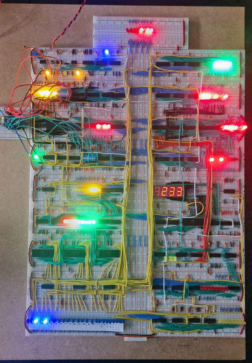
This repository contains my design of the Ben Eater 8-bit computer. I call it an 8-CPU instead of a computer because to me it feels more like a CPU.
If you were to do a checkout of this, it is basically a KiCad project folder. It will not contain all the symbols I used because the ones I designed I made global in KiCad, but I added a PDF of all the schematics.
You will also find my instruction set, the code to program the EEPROM's and the code to program the CPU which includes my test programs.
Below is a little badly written story of my journey.
I have always been intrigued by electronics by have never done anything with it.
A while back I found a video series by Ben Eater about building an 8-bit computer on breadboards (YouTube). Watching the series I learned a lot about how CPU's (could) work and was really fascinated. It all did not seem that complicated.
So after thinking about it for a while and checking my finances (It is not really cheap) I decided to build a variation of it. But first I did some research and set some goals.
The research taught me that I should not skimp on breadboard quality. There are a lot of people that write about this and the breadboards from BusBoard Prototype Systems seem to be one of the best.
Next I started digging into what types of 74 series logic chips there are. I learned that the 74LS series that Ben uses are TTL logic chips but they are rather power hungry. I decided I wanted to go with CMOS logic chips because they are more efficient. In the end I went for 74HCT chips. They are CMOS chips with TTL level support. I went for this because I don't really know anything about this and I was not sure if I needed TTL level support in some parts.
So the chip series was decided and the breadboard brand was decided, now I needed a way to get all these things. I started searching for those online and found the usual suspects:
I live in Belgium so delivery costs, import taxes and VAT were important. After a test order from Mouser I learned that they take care of the VAT and the import taxes, and when you order over 50 EUR (excluding VAT) the delivery is free. Just don't get caught at checkout because the prices on the site are without VAT.
I would also need a power supply. I did not want to use a cut open USB cable but wanted some extra features.
On Amazon I found this device that had all the features I wanted and it was not out of my budget.
Amazon was also used to buy the wires and initially some resistors. The wires were great and I ordered multiple of those because it seems this thing needs a lot of wire. The resistors I hated and did not use. The legs have a diameter of 0.3 mm which is just too thin. When you want to insert them into a breadboard they just bend. The resistors eventually also came from Mouser.
Next up, the goals of this build.
The 220 Ohm resistor on each LED really made me think about component placement. It dictated the layout on the breadboards. Unlike what Ben does in his videos I could not just go from an output pin to ground.
After all the orders arrived I started building my CPU module by module in the order of the videos. I would first design each module in KiCad and use my design to build it on breadboards.
While building I initially used 10k Ohm resistors to either pull-up or pull-down control signal pins. That way I could use a jumper wire to switch its state without the pin being floating during the transition. (The resistors were removed after wiring up the control signals.) The different modules were tested individually once they were finished.
When building the output module I noticed I did not order any 74HCT273 chips. So I changed my design to use what I had which were 74HCT173 D-type flip flops. In hindsight this seems to be a blessing in disguise because there seems to be a design issue with using the 74HCT273 as can be seen here.
After finishing the clock, program counter, a register, alu, b register, output, ram and instruction register I decided to combine them and wire them up to the bus. This is were I got hit with my first problem.
Whenever there were more than 4 LED's active in the RAM value and I would change the RAM output control signal (high to low or low to high) the RAM address register would reset. I searched for hours what the cause could be but never figured it out. I rewired stuff, replaced chips, disconnected modules from the bus, added pull-up and pull-down resisters, ... but everything stayed the same. Motivation really sank so drastic measures needed to be taken. Given the RAM address gets loaded by the program counter initially I decided I did not need a reset there and removed the reset line and tied the pins to ground. Problem solved.
Next I built the last 4 modules: control logic, CPU flags, X register and stack. When they were done I wired up everything. Guess what, things did not work as expected. Some of the problems I saw:
Those dreaded random resets were spreading. Given I have no oscilloscope I could not really see what was going on with reset line but after some mental gymnastics I figured there must be some noise getting to the reset line. Given I know nothing about electronics I started trying things.
When I put a 10nF capacitor on the reset line close to the reset pin and ground of the A register it no longer did the random reset but the button to reset everything still worked. I did the same with the X register and wired up the reset for the RAM address again with a 10nF capacitor. No more random resets. I still don't know why this is happening but it is fixed. Problem solved.
Next up were the random actions in the X register and stack. After searching the internet I found out that when you change the address on an EEPROM there is a period of time where the data is invalid (this is also in the datasheet). This shows itself by data pins going high or low randomly during the invalid period. This was triggering the random actions.
The first fix was not to trigger the load of the X register by just using an inverted control signal. I used the non inverted control signal and the clock through a NAND gate to trigger the load. This way the loading is tied to a clock transition which is in line with the rest of the design. This made things better but did not solve everything.
After some more searching on the internet I found a post where someone explained that the entire computer reacts to the rising edge of the clock. This includes the instruction register and the CPU flags which trigger address changes. If you were to change the address on the falling edge of the clock the 'blips' on the EEPROM output would not matter.
I first thought about using the inverted clock for the instruction register and the CPU flags but decided against it. I was not sure if this would have side effects. Given I had some room below the instruction register I decided to add two more 74HCT173 D-type flip flops to latch the instruction register and the CPU flags on the falling edge of each clock. These latched values are used as the address lines for the EEPROM's. This solved all the problems of random actions occurring.
Lastly there was the problem of the RAM not always writing. I was aware of issues with the RC circuit Ben has in his original design on the clock for the RAM input. I already put in a diode to prevent back feeding any voltage as the capacitor discharges but I was still suspicious. Given writing ram works with a push button in programming mode, which does not have an RC circuit on it, I figured it might work without. After removing the RC circuit and just passing in the clock everything worked.
I now have an 8-bit breadboard CPU which supports addition, subtraction, push, pop, subroutines, ...
I can program the CPU using the dip switches but that got old really quickly. I wrote a little Arduino application that could program the CPU. I just hook up the ground, the address lines, the data lines and write signal to the breadboard from an Arduino Nano Every. This saves a lot of time and does not discourage me from making changes and retesting.
On the internet there are many posts that say you have to add a lot of bulk capacitors to the breadboards in order to make it stable. My CPU does not seem to need it. It could be the quality of the breadboards, the fact that I used 74HCT chips or the quality of the power supply. When running my Fibonacci program it draws a maximum of 350 mA.
I used an alternative to the EEPROM programmer designed by Ben. Given I used an Arduino Nano Every, which has more digital pins, I did not have to combine the write signal into the shift registers. I did have to rewire it because my EEPROM's did not seems to have the content I expected.
| Qty | Value | Footprint | References |
|---|---|---|---|
| 130 | 220R | Resistor_THT:R_Axial_DIN0204_L3.6mm_D1.6mm_P7.62mm_Horizontal | R1, R100, R101, R102, R103, R104, R105, R107, R108, R109, R110, R111, R112, R113, R114, R116 +114 |
| 66 | 100n | 01_my_library:C_Disc_D4.0mm_W2.6mm_P2.50mm | C1, C2, C10, C11, C14, C15, C16, C18, C19, C20, C21, C22, C23, C24, C25, C26 +50 |
| 52 | RED | 01_my_library:LED_D5.0mm | D1, D13, D14, D15, D16, D17, D18, D19, D107, D108, D109, D110, D111, D112, D113, D114 +36 |
| 31 | 10k | Resistor_THT:R_Axial_DIN0204_L3.6mm_D1.6mm_P7.62mm_Horizontal | R10, R11, R12, R13, R14, R15, R16, R20, R24, R25, R59, R60, R61, R62, R106, R115 +15 |
| 28 | YELLOW | 01_my_library:LED_D5.0mm | D10, D12, D45, D46, D47, D48, D49, D50, D115, D116, D117, D118, D119, D120, D121, D122 +12 |
| 25 | BLUE | 01_my_library:LED_D5.0mm | D11, D81, D82, D83, D84, D85, D86, D87, D88, D89, D90, D100, D101, D102, D103, D104 +9 |
| 17 | GREEN | 01_my_library:LED_D5.0mm | D54, D56, D57, D58, D59, D60, D61, D62, D63, D75, D76, D77, D78, D79, D105, D106 +1 |
| 15 | 10n | 01_my_library:C_Disc_D4.0mm_W2.6mm_P2.50mm | C6, C8, C12, C13, C17, C28, C38, C45, C46, C50, C51, C54, C69, C75, C79 |
| 13 | 74HCT173 | Package_DIP:DIP-16_W7.62mm | U8, U9, U11, U12, U20, U21, U36, U38, U39, U40, U42, U43, U57 |
| 7 | 74HCT157 | Package_DIP:DIP-16_W7.62mm | U22, U23, U24, U25, U27, U28, U54 |
| 7 | 74HCT245 | Package_DIP:DIP-20_W7.62mm | U7, U10, U15, U18, U29, U60, U63 |
| 7 | MountingHole | MountingHole:MountingHole_3.2mm_M3 | H1, H2, H3, H4, H5, H6, H7 |
| 4 | 74HCT00 | Package_DIP:DIP-14_W7.62mm | U26, U41, U58, U59 |
| 4 | 74HCT04 | Package_DIP:DIP-14_W7.62mm | U2, U46, U48, U50 |
| 4 | 74HCT193 | Package_DIP:DIP-16_W7.62mm | U61, U62, U64, U65 |
| 4 | AT28C64B | Package_DIP:DIP-28_W15.24mm_Socket | U37, U47, U49, U51 |
| 4 | LMC555xN | Package_DIP:DIP-8_W7.62mm | U4, U5, U6, U34 |
| 3 | 1k | Resistor_THT:R_Axial_DIN0204_L3.6mm_D1.6mm_P7.62mm_Horizontal | R18, R19, R96 |
| 3 | 74HCT08 | Package_DIP:DIP-14_W7.62mm | U1, U53, U55 |
| 3 | 74HCT161 | Package_DIP:DIP-16_W7.62mm | U30, U31, U45 |
| 3 | Button | Button_Switch_THT:SW_PUSH_6mm | SW1, SW6, SW7 |
| 2 | 74HCT02 | Package_DIP:DIP-14_W7.62mm | U52, U56 |
| 2 | 74HCT283 | Package_DIP:DIP-16_W7.62mm | U16, U17 |
| 2 | 74HCT86 | Package_DIP:DIP-14_W7.62mm | U13, U14 |
| 2 | SW_DIP_x08 | Button_Switch_THT:SW_DIP_SPSTx08_Slide_9.78x22.5mm_W7.62mm_P2.54mm | SW3, SW4 |
| 1 | 100k | Resistor_THT:R_Axial_DIN0204_L3.6mm_D1.6mm_P7.62mm_Horizontal | R97 |
| 1 | 1m | Resistor_THT:R_Axial_DIN0204_L3.6mm_D1.6mm_P7.62mm_Horizontal | R22 |
| 1 | 1m | 01_my_library:Potentiometer_Bourns_3362U_Vertical | RV1 |
| 1 | 1u | Capacitor_THT:CP_Radial_D5.0mm_P2.00mm | C5 |
| 1 | 2_Complement_Header | Connector_PinSocket_2.54mm:PinSocket_1x02_P2.54mm_Vertical | J4 |
| 1 | 470u | Capacitor_THT:CP_Radial_D10.0mm_P5.00mm | C83 |
| 1 | 7130 | Package_DIP:DIP-48_W15.24mm | U19 |
| 1 | 74HCT107 | Package_DIP:DIP-14_W7.62mm | U32 |
| 1 | 74HCT138 | Package_DIP:DIP-16_W7.62mm | U44 |
| 1 | 74HCT139 | Package_DIP:DIP-16_W7.62mm | U33 |
| 1 | 74HCT32 | Package_DIP:DIP-14_W7.62mm | U3 |
| 1 | Arduino_Address_Programming_Header | Connector_PinSocket_2.54mm:PinSocket_1x09_P2.54mm_Vertical | J1 |
| 1 | Arduino_Data_Programming_Header | Connector_PinSocket_2.54mm:PinSocket_1x09_P2.54mm_Vertical | J2 |
| 1 | Arduino_Programming_Trigger_Header | Connector_PinSocket_2.54mm:PinSocket_1x02_P2.54mm_Vertical | J3 |
| 1 | LOGO | LOGO | CPU_LOGO |
| 1 | LTC-5723HR | Display_7Segment:CA56-12SURKWA | U35 |
| 1 | Power | Connector_PinSocket_2.54mm:PinSocket_1x02_P2.54mm_Vertical | J6 |
| 1 | Programming Switch | 01_my_library:Mini_Slide_Switch_CUI_THT_123 | SW5 |
| 1 | Switch | 01_my_library:Mini_Slide_Switch_CUI_THT_123 | SW2 |
| 1 | USB_B_Micro | Connector_USB:USB_Micro-B_Amphenol_10118194_Horizontal | J5 |
It measures 244.5 × 393.4 mm and has 4 copper layers, 1.6 mm thick.
458 parts, built around the 74HCT245, 74HCT173D, 74HCT157D and 74HCT00D. The full list of its parts is on this page, with links to each part's symbol and footprint where PCBKit's library has them.
From the nurk/8-bit-cpu repository on GitHub, at the commit this page was made from: the board is 8-bit-cpu.kicad_pcb and its schematic 8-bit-cpu.kicad_sch. PCBKit opens the board in the browser, with nothing to install.
Its repository states no licence, so its author keeps all rights: ask nurk before reusing the design.


ksr/p8x
Generated by generators/genkicad.py from the canonical geneagle netlist (CARDS["peripheral-card"]), same standard as the memory card: 4-layer (F/B signals, In1=GND, In2=VCC planes), a bypass cap above each IC, a…

flypie/Gigatron
This is a version of the files from https://gigatron.io/ altered to work on a vanilla KiCAD 5.1.6. Changes are minimal in the schematic and PCB, layout has only been changed where dimensions or orientations changed as a…


