2 layers35.6 × 94.6 mm

 potpurri/A1-External-ESP8266-Cooling-Fan-Module
ESP8266-board driving an external fan for improved cooling of nozzle and prints
A1-External ESP8266-Cooling Fan Module is an open-source printed circuit board by potpurri, from the potpurri/A1-External-ESP8266-Cooling-Fan-Module repository on GitHub, published under the Apache-2.0 licence. It is a 4-layer board of 66 × 57 mm with 74 parts on 67 nets, routed with 314 tracks and 274 vias.
It is built around the CH340C, AM2320 and LM2596S-ADJ, with the AMS1117-3.3, SRV05-4 and SI2300 among its other parts. Its parts include 27 resistors, 10 capacitors, 10 diodes, 8 connectors and 6 ICs. It belongs with the ESP8266 boards of this library.


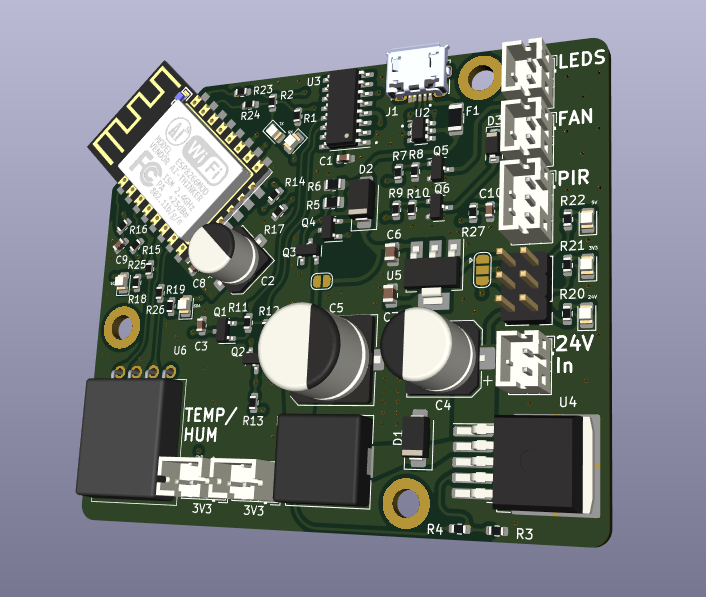
This project showcases an ESP8266-based board designed to control an external fan to enhance nozzle and print cooling on the Bambu Lab A1 3D printer. The PCB consists of 4 layers in the stack-up: signals, ground, power, and signals.
Note: This project is a work in progress.
The board includes the following components:
Below are images of the PCB:
3D render of the front view of the PCB
3D render of the back view of the PCB
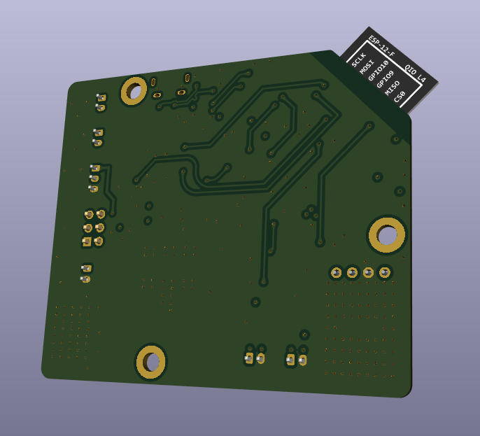
Front view of the actual PCB
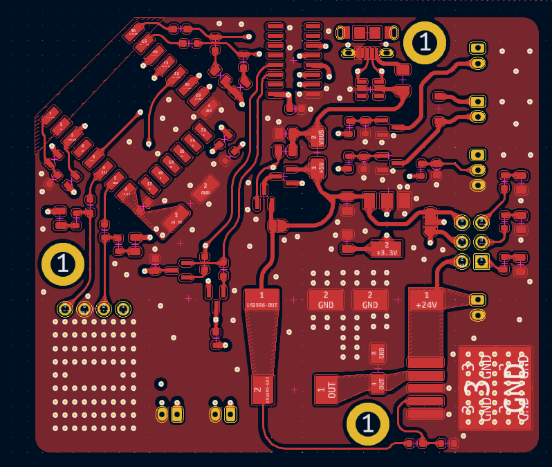
Ground layer of the PCB stack-up
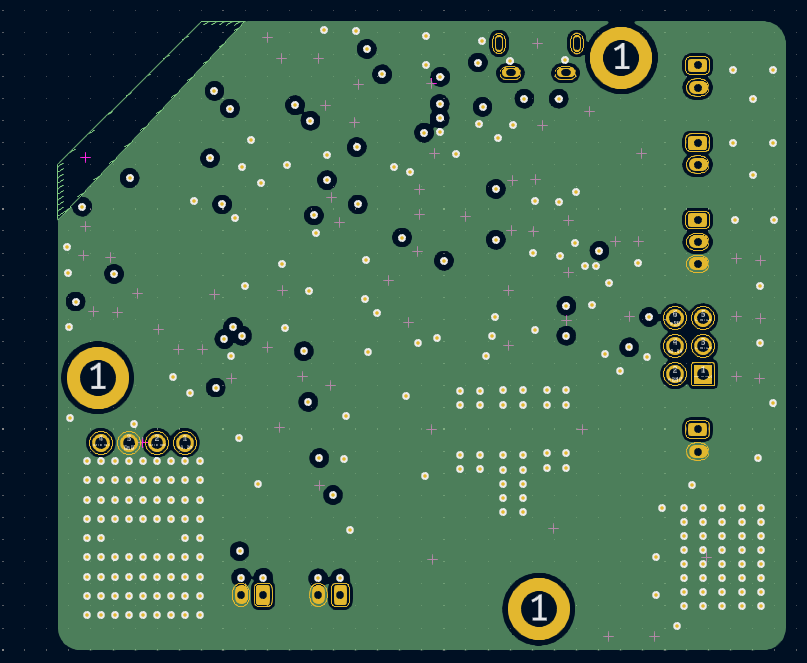
Power layer of the PCB stack-up
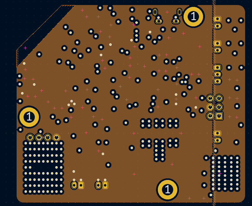
Back view of the PCB
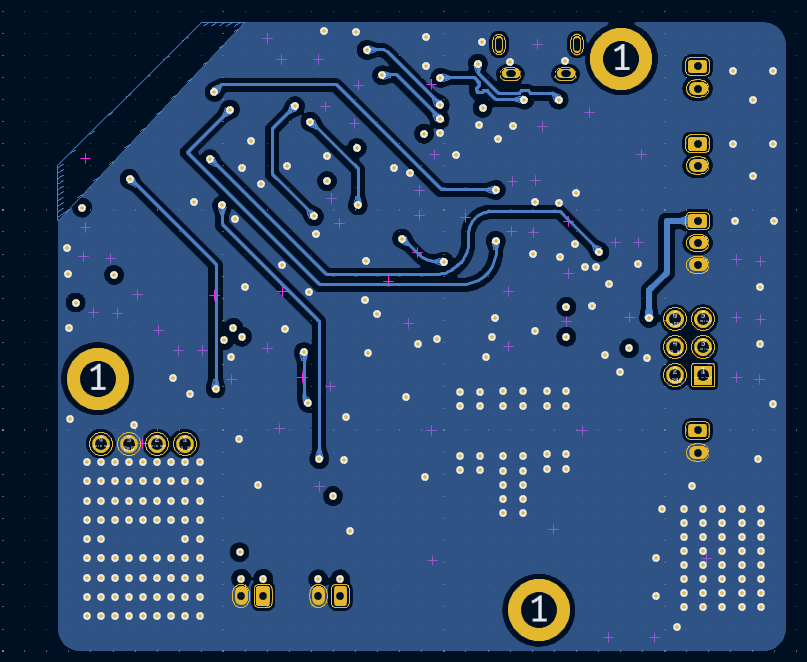
For detailed schematics, please refer to the schematic PDF.
| Qty | Value | Footprint | References |
|---|---|---|---|
| 9 | 0 | Resistor_SMD:R_0603_1608Metric | R7, R9, R11, R12, R23, R24, R25, R26, R27 |
| 7 | 10k | Resistor_SMD:R_0603_1608Metric | R8, R10, R13, R14, R15, R16, R17 |
| 7 | LED | LED_SMD:LED_0805_2012Metric | D4, D5, D6, D7, D8, D9, D10 |
| 4 | 1k | Resistor_SMD:R_0603_1608Metric | R1, R2, R18, R19 |
| 4 | SI2300 | USB:SI2300 SOT-23 | Q1, Q2, Q5, Q6 |
| 3 | 100n | Capacitor_SMD:C_0603_1608Metric | C1, C8, C10 |
| 3 | MountingHole | MountingHole:MountingHole_3.2mm_M3_DIN965_Pad | H1, H2, H3 |
| 2 | 10u | Capacitor_SMD:C_0805_2012Metric | C6, C7 |
| 2 | 3V3 OUT | Connector_JST:JST_PH_B2B-PH-K_1x02_P2.00mm_Vertical | J6, J8 |
| 2 | SI2301 | Package_TO_SOT_SMD:SOT-23 | Q3, Q4 |
| 2 | SS34 | Diode_SMD:D_SMA | D1, D2 |
| 1 | 100u | Capacitor_SMD:CP_Elec_6.3x7.7 | C2 |
| 1 | 100u | Capacitor_SMD:CP_Elec_8x10.5 | C4 |
| 1 | 10k | Resistor_SMD:R_0805_2012Metric | R6 |
| 1 | 130 | Resistor_SMD:R_0603_1608Metric | R21 |
| 1 | 1A5 | Fuse:Fuse_1206_3216Metric | F1 |
| 1 | 1N4148 | Diode_SMD:D_SOD-123 | D3 |
| 1 | 1k | Resistor_SMD:R_0805_2012Metric | R5 |
| 1 | 1k2 | Resistor_SMD:R_0603_1608Metric | R3 |
| 1 | 1u | Capacitor_SMD:C_0603_1608Metric | C3 |
| 1 | 220u | Capacitor_SMD:CP_Elec_10x10.5 | C5 |
| 1 | 24V IN | Connector_JST:JST_PH_B2B-PH-K_1x02_P2.00mm_Vertical | J5 |
| 1 | 2k2 | Resistor_SMD:R_0603_1608Metric | R20 |
| 1 | 300 | Resistor_SMD:R_0603_1608Metric | R22 |
| 1 | 330m | Inductor_SMD:L_10.4x10.4_H4.8 | L1 |
| 1 | 3k9 | Resistor_SMD:R_0603_1608Metric | R4 |
| 1 | 470p | Capacitor_SMD:C_0603_1608Metric | C9 |
| 1 | AM2320 | Custom:AM2320 | U6 |
| 1 | AMS1117-3.3 | Package_TO_SOT_SMD:SOT-223-3_TabPin2 | U5 |
| 1 | CH340C | Package_SO:SOIC-16_3.9x9.9mm_P1.27mm | U3 |
| 1 | Cutoff bypass | Jumper:SolderJumper-2_P1.3mm_Open_RoundedPad1.0x1.5mm | JP2 |
| 1 | ESP12-F | ESP8266:ESP-12E_SMD | U1 |
| 1 | Fan connector | Connector_JST:JST_PH_B2B-PH-K_1x02_P2.00mm_Vertical | J2 |
| 1 | LEDS | Connector_PinHeader_2.54mm:PinHeader_2x03_P2.54mm_Vertical | J7 |
| 1 | LM2596S-ADJ | Package_TO_SOT_SMD:TO-263-5_TabPin3 | U4 |
| 1 | Leds connector | Connector_JST:JST_PH_B2B-PH-K_1x02_P2.00mm_Vertical | J3 |
| 1 | PIR sensor | Connector_JST:JST_PH_B3B-PH-K_1x03_P2.00mm_Vertical | J4 |
| 1 | SRV05-4 | Package_TO_SOT_SMD:SOT-23-6 | U2 |
| 1 | SolderJumper_3_Open | Jumper:SolderJumper-3_P1.3mm_Open_RoundedPad1.0x1.5mm | JP1 |
| 1 | USB_B_Micro | USB:AMPHENOL_10118194-0001LF | J1 |


ilomon10/embedded-totalizer-hour-meter
ESP32 engine hour meter & totalizer: firmware, SensorFrame protocol, Node host tools, KiCad PCB and a Deno device simulator

Legohead259/Vacuum-Tweezers-ECAD
KiCAD repository for the electrical designs for the SL_ST vacuum tweezer design


SEAS2025/mmwave-deer-scan
mmWave FMCW radar deer detection for roadside ambulance safety

akbar-q/Circuits-PCB-HardwareDesign
The High Voltage Arc Detector is a non-contact RF-based sensing system that detects high-voltage electrical arcs.
It measures 66 × 57 mm and has 4 copper layers, 1.6 mm thick.
74 parts, built around the CH340C, AM2320, LM2596S-ADJ and AMS1117-3.3. The full list of its parts is on this page, with links to each part's symbol and footprint where PCBKit's library has them.
From the potpurri/A1-External-ESP8266-Cooling-Fan-Module repository on GitHub, at the commit this page was made from: the board is A1-External-ESP8266-Cooling-Fan-Module/A1-External-ESP8266-Cooling-Fan-Module.kicad_pcb and its schematic A1-External-ESP8266-Cooling-Fan-Module/A1-External-ESP8266-Cooling-Fan-Module.kicad_sch. PCBKit opens the board in the browser, with nothing to install.
Its repository publishes it under the Apache-2.0 licence: you may reuse it on that licence's terms (keep the author's notice, and for a copyleft licence share your changes alike).