2 layers88 × 91 mm
Hour meter devboard
ilomon10/embedded-totalizer-hour-meter
ESP32 engine hour meter & totalizer: firmware, SensorFrame protocol, Node host tools, KiCad PCB and a Deno device simulator
27 parts

 ilomon10/embedded-totalizer-hour-meter
ESP32 engine hour meter & totalizer: firmware, SensorFrame protocol, Node host tools, KiCad PCB and a Deno device simulator
Hour meter board microfit can handroute is an open-source printed circuit board by ilomon10, from the ilomon10/embedded-totalizer-hour-meter repository on GitHub. It is a 2-layer board of 100 × 100 mm with 152 parts on 141 nets, routed with 242 tracks and 9 vias.
It is built around the CH340C, ESP32-WROOM-32E-N4 and MAX13223EEUP+T, with the THVD2410DRB, TJA1051T/3/1J and ADS1115IDGST among its other parts. Its parts include 50 resistors, 37 capacitors, 18 diodes, 17 ICs and 4 fuses. It belongs with the ESP32 boards of this library.


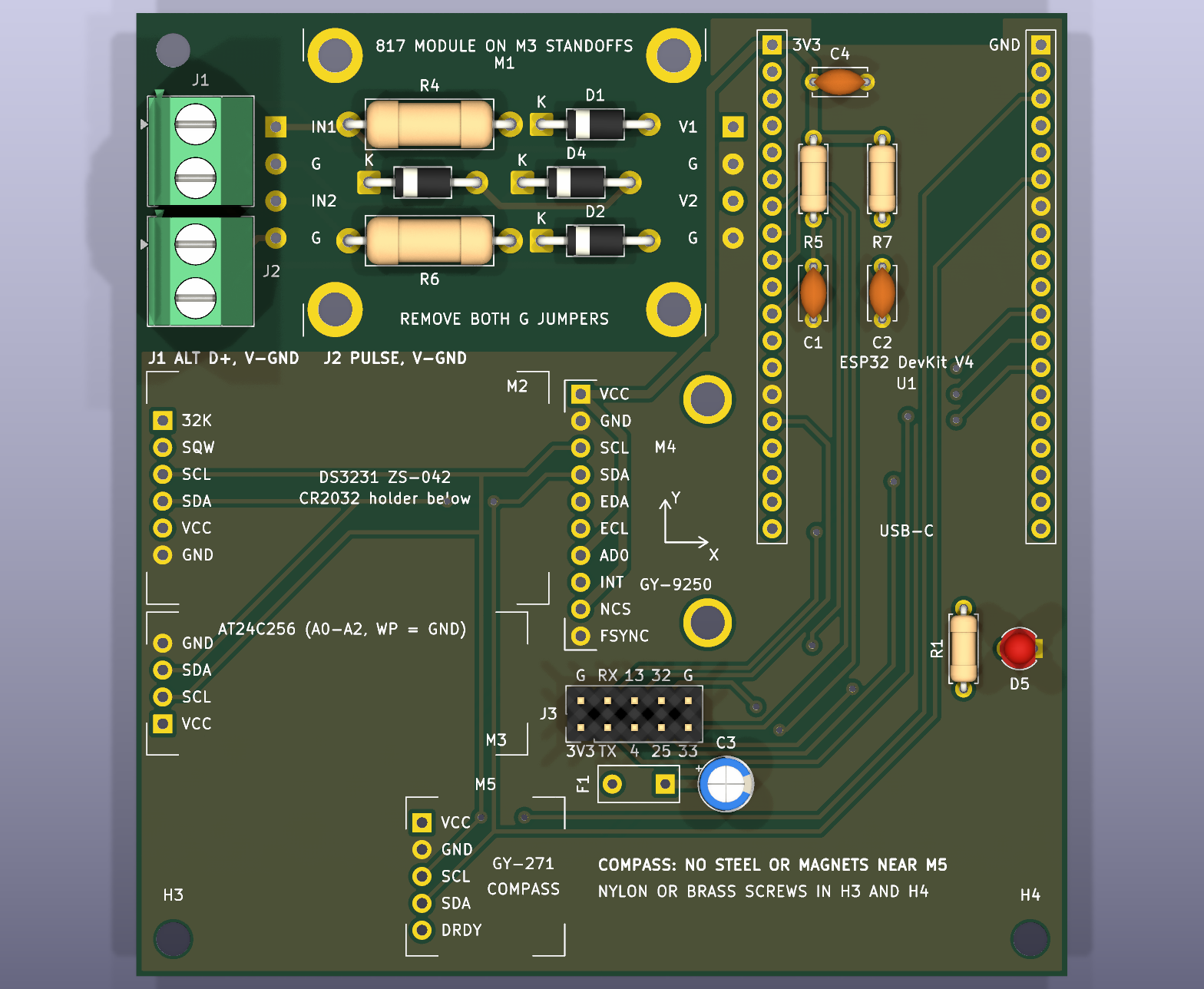
An 88 × 91 mm, 2-layer, through-hole carrier for ready-made modules from Indonesian electronics shops:
The DevKit's USB-C is the only supply. Vehicle wires go to screw terminals, and every other part is a common THT part.
The devboard is rev D of the module carrier: rev C plus a socket for a GY-271 compass, on a board 20 mm taller (Changes from rev C). GY-9250 modules sold locally often carry an MPU6500, which has no compass; the GY-271 always has one. The firmware pins are those of the earlier carriers, so it runs the esp32dev build.
| Schematic | hour-meter-devboard.kicad_sch (PDF: hour-meter-devboard.pdf, picture: hour-meter-devboard.png) |
| PCB | hour-meter-devboard.kicad_pcb (pictures: hour-meter-devboard-pcb.png, hour-meter-devboard-3d.png) |
| Ready to order | production/hour-meter-devboard-gerbers.zip (Gerbers + drill files) |
| Parts list | production/hour-meter-devboard-bom.csv: what to buy, with the search terms local shops use |
| LCSC order | production/hour-meter-devboard-lcsc-upload.csv for LCSC's BOM tool, and -lcsc-parts.csv with part numbers, stock and fit notes (Buying the parts) |
| Check before ordering | production/hour-meter-devboard-fit-check-1to1.pdf: print at 100 % and lay the modules on it |
| Custom parts | hour-meter-modules.kicad_sym (symbols), hour-meter-modules.pretty/ (footprints, from tools-gen-footprints.py) |
| Input simulations | fault analysis, V4 module carrier group |
| Firmware | pio run -e esp32dev -t upload in esp32/ (the default build); module wiring and tests in WIRING.md |
Checks at release (rev D, 2026-11-04, after the hand edits and their audit):
| Ref | Part | Connects to |
|---|---|---|
| U1 | ESP32 DevKit V4 on 2 × 19 sockets. The antenna overhangs the top edge; the USB-C end points down | everything |
| M1 | 817 module on 4 M3 standoffs, above its own input protection | J1/J2 inputs → GPIO27/GPIO26 |
| M2, M3, M4 | DS3231, AT24C256 and GY-9250, lying flat on sockets, chip side up | I2C, 3V3 |
| M5 | GY-271 compass, lying flat on a 1×5 socket in the bottom strip, far from the DevKit and the RTC battery | I2C, 3V3; DRDY not connected |
| J1, J2 | Screw terminals: alternator (D+/L) and 12/24 V pulse; pin 2 = vehicle ground | M1 inputs |
| J3 | Spare 2 × 5 header: UART2 and five GPIOs, 3V3 through F1 | U1 |
| D5 | Status LED (green, 3 mm) | GPIO2 |
| ESP32 pin | Use | I2C address | Device | |
|---|---|---|---|---|
| GPIO21 / 22 | I2C SDA / SCL (100 kHz, module pull-ups) | 0x50 | AT24C256 (A0–A2 = GND) | |
| GPIO27 | ALT_IN, from J1 through 817 channel 1 (LOW = running) | 0x68 | DS3231 | |
| GPIO26 | PULSE_IN, from J2 through 817 channel 2 | 0x57 | AT24C32 on the ZS-042 (unused) | |
| GPIO17 / 16 | UART2 TX / RX on J3 | 0x69 | MPU9250 / 6500 (AD0 = 3V3) | |
| GPIO4, 13, 25, 32, 33 | Spare, on J3 | 0x0C | AK8963 magnetometer (MPU9250 only) | |
| GPIO2 | Status LED D5, active high. The firmware doesn't drive it yet | 0x0D | QMC5883L on the GY-271 (most modules sold today) | |
| 0x1E | HMC5883L on older GY-271 modules |
J3, seen from the top (labels on the silkscreen, full pinout on the back):
upper row   2 GND    4 RX2 (IO16)   6 IO13   8 IO32   10 GND
lower row   1 3V3*   3 TX2 (IO17)   5 IO4    7 IO25    9 IO33        * through F1, 0.1 A PTC
J3 is for 3.3 V logic only, and nothing on it is vehicle-proof. GPIO12, 14 and 15 are left off: 12 and 15 are boot strapping pins, and 14 puts out PWM at boot.
The module footprints use typical clone dimensions. Print production/hour-meter-devboard-fit-check-1to1.pdf at 100 % (no "fit to page"). Check that the board outline measures 88 × 91 mm, then lay each module on its outline: the pins must land on the pads. If one doesn't fit, change its numbers in tools-gen-footprints.py and regenerate (see the end).
| Part | Assumed | Check |
|---|---|---|
| ESP32 DevKit V4 | 2 × 19 pins, rows 25.4 mm apart (Espressif's DevKitC footprint), antenna about 7 mm beyond pin 1 | Some narrow 38-pin clones use 22.86 mm |
| 817 module | 38 × 29 mm, 4 × M3 holes 32 × 24 mm apart | Only one seller lists the hole spacing |
| GY-9250 | 15.5 × 25.5 mm, 10 pins down the left edge; M3 holes 12 mm right of the pins, 0.5 mm and 21.6 mm below pin 1 | The holes come from a photo. If they don't line up, leave the two standoffs out |
| DS3231 ZS-042 | 38 × 22 mm, 1 × 6 pins on one short edge, 32K at the top | |
| AT24C256 | About 36 × 13.5 mm, 4 pins on one short edge: GND, SDA, SCL, VCC from the top | Other boards differ: match the labels |
| GY-271 | Up to 15 × 15 mm, 5 pins: VCC, GND, SCL, SDA, DRDY from the top | Sellers list 13–15 mm; check the pin order on yours |
| F1 | 5.0 mm lead pitch |
Upload production/hour-meter-devboard-gerbers.zip to a local PCB maker or to JLCPCB / PCBWay (both ship to Indonesia).
| Setting | Value |
|---|---|
| Layers, size | 2 layers, 88 × 91 mm, FR-4 1.6 mm, 1 oz copper |
| Finish, colour | HASL (lead-free is fine), any colour, silkscreen on both sides |
| Smallest track / gap | 0.4 mm / 0.3 mm (0.8 mm between vehicle and logic copper) |
| Smallest hole | 0.6 mm (vias, 1.2 mm pads); component holes 0.8–1.3 mm, mounting holes 3.2 mm |
| Silkscreen text | 1.0 mm and up |
These rules are coarser than most fabs need, so a local maker who can't do fine tracks can still make this board. No assembly service is needed.
Everything is in production/hour-meter-devboard-bom.csv, with a search term for Tokopedia, Shopee or a shop counter. Besides the five modules and the THT parts, it lists:
From LCSC, together with the JLCPCB order: upload production/hour-meter-devboard-lcsc-upload.csv in LCSC's BOM tool.
-lcsc-parts.csv gives every part's stock, its fit against the footprint, and the optional lines (P6KE18A, GY-9250 standoffs).Fit notes for the LCSC parts:
D3/D4: the 1N4744A (15 V, 1 W zener) suits 12 V vehicles, and 24 V vehicles whose alternator clamps load dump (all recent ones). On an older 24 V truck without that clamp, fit a P6KE18A TVS in the same holes instead (simulation).
Every module lies flat, chip side up, on a standard 8.5 mm female socket. Each needs a straight pin header soldered on its underside, pointing down.
hour-meter /dev/ttyUSB0).hour-meter read /dev/ttyUSB0 --imu shows the IMU live.Vehicle netclass, with 0.8 mm clearance.| Rev C | Rev D (this board) | |
|---|---|---|
| Compass | only the GY-9250's AK8963, which MPU6500 modules lack | GY-271 on its own 1×5 socket (M5) |
| Size | 88 × 71 mm | 88 × 91 mm: a 20 mm strip along the bottom for the compass |
| Mounting holes | H3 under the AT24C256, H4 at the right edge | 3 holes: H1 top left, H3 and H4 in the bottom corners (nylon or brass screws). H2 under the DevKit was removed |
| Silkscreen | compass warning beside M5; rev D on the back | |
| Everything else | unchanged: same modules, input protection, vehicle zone and pins. Re-routed (Freerouting, then by hand), so the tracks differ |
The input circuit is unchanged since rev C, so its input simulations apply as they are.
Earlier carriers: rev C (hour-meter-esp32-v4) and rev A (hour-meter-esp32) were removed from the repository on 2026-11-04, when this board was renamed from hour-meter-esp32-v4-compass to hour-meter-devboard. They are in the git history at commit d35ef2d, for example git show d35ef2d:schematic/hour-meter-esp32-v4/README.md.
After the scripts made the board, it was edited by hand in KiCad on 2026-11-04:
The audit then fixed three things:
| Found | Fix |
|---|---|
| Two dimension lines on F.Cu: they would have been etched in copper, touching the board edge | Moved to User.Drawings and measured edge to edge: 88 × 91 mm |
| The GND pour's corner had moved 2 mm into the vehicle zone. It came 1.5 mm from J2's vehicle-ground pin (was 3.8 mm) and 2.7 mm from D1/D2's input pads (was 4.7 mm) | Corner put back: 3.8 mm and 4.7 mm again |
| R1's reference printed over D5's pad | Moved beside R1 |
After the audit, the +3V3 track beside the vehicle zone was re-drawn 0.4 mm closer to the zone. It is now 4.3 mm from D1/D2's input pads (was 4.7 mm). DRC is still clean, and the closest logic copper is still the GND pour, 3.8 mm from J2's vehicle-ground pin. The production files were rebuilt from this final board.
Smoke test, simulated on the final copper:
| Test | Result |
|---|---|
| Vehicle inputs, 11 ngspice cases (fault analysis) | Unchanged: 10 pass. The unclamped 24 V load dump needs the P6KE18A option |
| 3V3 to the modules (14 mA) | Within 0.8 mV of the DevKit's 3V3; within 8.2 mV with 100 mA drawn from J3 |
| Field at the GY-271 from the supply currents | 0.07 µT (about 0.1°); 0.95 µT with 100 mA drawn from J3 |
| I2C | SCL 229 mm and SDA 209 mm of track. Estimated rise time about 120 ns; 1000 ns is allowed at 100 kHz |
| Part heights | Under the DevKit, at most about 7 mm (8 mm free). C3 and F1 sit outside every module. Only R1 (2.5 mm) is under the USB plug |
The board is now hand-routed. Running tools-build-pcb.py place or tools-route-pcb.py again would replace the hand edits with a fresh placement and Freerouting result. After a change in KiCad, run only tools-production.py.
The board was first produced by scripts:
python3 tools-gen-footprints.py      # 1. module footprints (edit dimensions after measuring)
python3 tools-build-pcb.py place     # 2. netlist -> footprints -> placement (PLACEMENT table); `check` = dry run
python3 tools-route-pcb.py           # 3. keep-outs and fence -> Freerouting -> GND pours
python3 tools-production.py # 4. 2-layer and DRC checks -> Gerbers zip, BOM, fit-check PDF, picturestools-build-pcb.py puts each reference beside its part, where it touches no pad or other silkscreen.hour-meter-devboard.kicad_pro in KiCad, move parts and route interactively. Run tools-production.py afterwards for the checks and files.| Qty | Value | Footprint | References |
|---|---|---|---|
| 24 | 100nF | Capacitor_SMD:C_0603_1608Metric | C101, C105, C202, C204, C207, C301, C401, C402, C501, C601, C1001, C1002, C1101, C1102, C1103, C1105 +8 |
| 9 | 10k | Resistor_SMD:R_0603_1608Metric | R201, R202, R205, R206, R401, R501, R701, R702, R703 |
| 6 | 1k | Resistor_SMD:R_1206_3216Metric | R301, R302, R303, R306, R307, R308 |
| 5 | 330R | Resistor_SMD:R_0603_1608Metric | R705, R706, R808, R809, R810 |
| 4 | 1uF | Capacitor_SMD:C_0603_1608Metric | C203, C208, C604, C1104 |
| 4 | 4.7k | Resistor_SMD:R_0603_1608Metric | R211, R212, R304, R309 |
| 4 | M3 | MountingHole:MountingHole_3.2mm_M3 | H102, H103, H104, H105 |
| 3 | 100R | Resistor_SMD:R_0603_1608Metric | R803, R804, R805 |
| 3 | 100k | Resistor_SMD:R_0603_1608Metric | R806, R807, R905 |
| 3 | 1k | Resistor_SMD:R_0603_1608Metric | R104, R209, R210 |
| 2 | 0.2A | Fuse:Fuse_1206_3216Metric | F801, F803 |
| 2 | 10uF 25V | Capacitor_SMD:C_0805_2012Metric | C201, C205 |
| 2 | 120R | Resistor_SMD:R_0805_2012Metric | R704, R1001 |
| 2 | 22k | Resistor_SMD:R_0603_1608Metric | R305, R310 |
| 2 | 470R | Resistor_SMD:R_0603_1608Metric | R203, R204 |
| 2 | 49.9k 0.1% | Resistor_SMD:R_1206_3216Metric | R901, R902 |
| 2 | 5.1k | Resistor_SMD:R_0603_1608Metric | R207, R208 |
| 2 | BZT52C4V7S | Diode_SMD:D_SOD-323 | D302, D304 |
| 2 | M7 | Diode_SMD:D_SMA | D301, D303 |
| 2 | MMBT3904 | Package_TO_SOT_SMD:SOT-23 | Q201, Q202 |
| 2 | PC817C-S | Package_DIP:SMDIP-4_W9.53mm | U301, U302 |
| 2 | SS54 | Diode_SMD:D_SMA | D103, D105 |
| 2 | SZNUP3105LT1G | Package_TO_SOT_SMD:SOT-23 | D701, D1001 |
| 1 | +3V3 | TestPoint:TestPoint_Pad_D1.0mm | TP807 |
| 1 | 0.5A 60V | Fuse:Fuse_1812_4532Metric | F101 |
| 1 | 0.5A 6V | Fuse:Fuse_1206_3216Metric | F201 |
| 1 | 0R | Resistor_SMD:R_0603_1608Metric | R213 |
| 1 | 100k | Resistor_SMD:R_1206_3216Metric | R101 |
| 1 | 100nF 50V | Capacitor_SMD:C_0603_1608Metric | C103 |
| 1 | 10k 0.1% | Resistor_SMD:R_0603_1608Metric | R903 |
| 1 | 10nF | Capacitor_SMD:C_0603_1608Metric | C602 |
| 1 | 10nF 1kV | Capacitor_SMD:C_1206_3216Metric | C901 |
| 1 | 120R 0.1% DNP | Resistor_SMD:R_1206_3216Metric | R904 |
| 1 | 1N4148W | Diode_SMD:D_SOD-123 | D102 |
| 1 | 1nF | Capacitor_SMD:C_0603_1608Metric | C302 |
| 1 | 2.2k | Resistor_SMD:R_0603_1608Metric | R105 |
| 1 | 220uF 16V | Capacitor_SMD:CP_Elec_6.3x7.7 | C104 |
| 1 | 220uF 50V | Capacitor_SMD:CP_Elec_10x10 | C102 |
| 1 | 22uF | Capacitor_SMD:C_0805_2012Metric | C206 |
| 1 | 3.3k | Resistor_SMD:R_0603_1608Metric | R103 |
| 1 | 33uH 3A | Inductor_SMD:L_12x12mm_H8mm | L101 |
| 1 | 5.6k | Resistor_SMD:R_0603_1608Metric | R102 |
| 1 | ADS1115IDGST | Package_SO:TSSOP-10_3x3mm_P0.5mm | U901 |
| 1 | AMS1117-3.3 | Package_TO_SOT_SMD:SOT-223-3_TabPin2 | U204 |
| 1 | AT24C256C-SSHL-T | Package_SO:SOIC-8_3.9x4.9mm_P1.27mm | U501 |
| 1 | B5819W | Diode_SMD:D_SOD-123 | D201 |
| 1 | BAV99 | Package_TO_SOT_SMD:SOT-23 | D901 |
| 1 | BIAS A | Jumper:SolderJumper-2_P1.3mm_Open_RoundedPad1.0x1.5mm | JP703 |
| 1 | BIAS B | Jumper:SolderJumper-2_P1.3mm_Open_RoundedPad1.0x1.5mm | JP704 |
| 1 | BOOT | Button_Switch_SMD:SW_Push_1P1T_XKB_TS-1187A | SW202 |
| 1 | BSP75N | Package_TO_SOT_SMD:SOT-223 | U903 |
| 1 | CAN LISTEN-ONLY | Jumper:SolderJumper-2_P1.3mm_Open_RoundedPad1.0x1.5mm | JP1002 |
| 1 | CAN TERM 120R | Jumper:SolderJumper-2_P1.3mm_Open_RoundedPad1.0x1.5mm | JP1001 |
| 1 | CH340C | Package_SO:SOIC-16_3.9x9.9mm_P1.27mm | U202 |
| 1 | CR2032 | Battery:BatteryHolder_MYOUNG_BS-07-A1BJ001_CR2032 | BT401 |
| 1 | DS3231MZ+TRL | Package_SO:SOIC-8_3.9x4.9mm_P1.27mm | U401 |
| 1 | ESP32-WROOM-32E-N4 | RF_Module:ESP32-WROOM-32E | U201 |
| 1 | GND | TestPoint:TestPoint_Pad_D1.0mm | TP808 |
| 1 | GPS (GH 6-pin) | Connector_JST:JST_GH_SM06B-GHS-TB_1x06-1MP_P1.25mm_Horizontal | J802 |
| 1 | GPS VCC 3V3/5V | Jumper:SolderJumper-3_P1.3mm_Bridged12_RoundedPad1.0x1.5mm | JP801 |
| 1 | LIS3MDLTR | Package_LGA:LGA-12_2x2mm_P0.5mm | U602 |
| 1 | LM2596S-ADJ | Package_TO_SOT_SMD:TO-263-5_TabPin3 | U101 |
| 1 | MAX13223E | Package_SO:TSSOP-20_4.4x6.5mm_P0.65mm | U1101 |
| 1 | MPU-6500 | Sensor_Motion:InvenSense_QFN-24_3x3mm_P0.4mm | U601 |
| 1 | Micro-Fit 3.0 2x8 | Connector_Molex:Molex_Micro-Fit_3.0_43045-1600_2x08_P3.00mm_Horizontal | J1 |
| 1 | P1 (green) | LED_SMD:LED_Kingbright_APA1606_1.6x0.6mm_Horizontal | D801 |
| 1 | P2 (green) | LED_SMD:LED_Kingbright_APA1606_1.6x0.6mm_Horizontal | D802 |
| 1 | PPS | TestPoint:TestPoint_Pad_D1.0mm | TP801 |
| 1 | PWR (red) | LED_SMD:LED_0603_1608Metric | D202 |
| 1 | PWR red | LED_SMD:LED_0603_1608Metric | D106 |
| 1 | QWIIC | Connector_JST:JST_SH_SM04B-SRSS-TB_1x04-1MP_P1.00mm_Horizontal | J803 |
| 1 | RESET | Button_Switch_SMD:SW_Push_1P1T_XKB_TS-1187A | SW201 |
| 1 | SMAJ30CA | Diode_SMD:D_SMA | D104 |
| 1 | SN74AHCT1G125DBVR | Package_TO_SOT_SMD:SOT-23-5 | U902 |
| 1 | SRV05-4 | Package_TO_SOT_SMD:SOT-23-6 | U802 |
| 1 | SS34 | Diode_SMD:D_SMA | D101 |
| 1 | STATUS (yellow) | LED_SMD:LED_0603_1608Metric | D203 |
| 1 | TERM 120R | Jumper:SolderJumper-2_P1.3mm_Open_RoundedPad1.0x1.5mm | JP702 |
| 1 | THVD2410DR | Package_SO:SOIC-8_3.9x4.9mm_P1.27mm | U701 |
| 1 | TJA1051T/3 | Package_SO:SOIC-8_3.9x4.9mm_P1.27mm | U1001 |
The 148 most common of 152 parts.
ilomon10/embedded-totalizer-hour-meter
ESP32 engine hour meter & totalizer: firmware, SensorFrame protocol, Node host tools, KiCad PCB and a Deno device simulator

JuanPoueriet/automatic-spork
Máquina de ruleta física de casino. 6 PCBs: pic32main (cerebro), wheel (rueda de LEDs), displaysa/b/c (paneles de 7 segmentos en cascada) y buttons (botonera).

ThatguyCplus/throttleECU
STM32F411CE Throttle ECU — PID position control with AS5048A encoder, H-bridge motor, safety module


Cadburies/SisuAssistant
Sailing yacht Sisu: Home Assistant + ESPHome Marine Board (alternator regulation, tanks) + MQTT kernel, Signal K/Grafana/InfluxDB on a NAS, and Sisu Nav chart & weather-routing cockpit.

colinleroy/BurgerDisk
A daisy-chainable Smartport hard drive for the Apple II

nhallsny/faraday-rescue
Open source battery for e-bikes made by the now-defunct Faraday Bicycles

nuerolynx/embedded-systems-lab
Arduino UNO R4 WiFi and ESP32 prototypes for access control, automation, displays, monitoring, and Bluetooth audio.

It measures 100 × 100 mm and has 2 copper layers, 1.6 mm thick.
152 parts, built around the CH340C, ESP32-WROOM-32E-N4, MAX13223EEUP+T and THVD2410DRB. The full list of its parts is on this page, with links to each part's symbol and footprint where PCBKit's library has them.
From the ilomon10/embedded-totalizer-hour-meter repository on GitHub, at the commit this page was made from: the board is schematic/hour-meter-board/backup-before-schematic-remake/hour-meter-board-microfit-can-handroute.kicad_pcb and its schematic schematic/hour-meter-board/ain1-adc.kicad_sch. PCBKit opens the board in the browser, with nothing to install.
Its repository states no licence, so its author keeps all rights: ask ilomon10 before reusing the design.