2 layers61 × 64.1 mm
Rfreplacement
c0pperdragon/C64-Video-Enhancement
Component video modification for the C64 8-bit computer
98 parts286MIT

 pmandes/C64-RF-Modulator9
Commodore C64C RF modulator replacement with S-Video and stereo audio output.
Rfreplacement is an open-source printed circuit board by pmandes, from the pmandes/C64-RF-Modulator repository on GitHub, published under the MIT licence. It is a 2-layer board of 55.9 × 43.9 mm with 36 parts on 25 nets, routed with 135 tracks and 26 vias.
It is built around the THS7316D and LM1117-3.3. Its parts include 11 resistors, 5 capacitors and 3 connectors. It belongs with the retro computing and games and audio and music boards of this library.


This is a project of a modulator replacement based on an analog c0pperdragon module. It was adjusted in size to the Commodore C64C motherboard and extended with S-Video and Strereo Audio outputs.
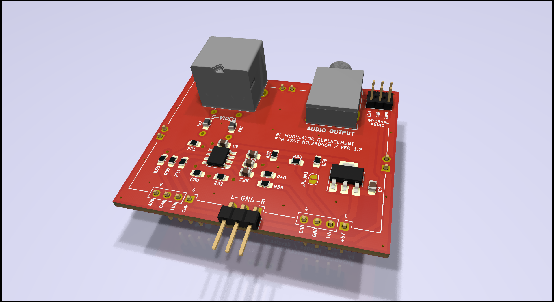
1.2
1.1
1.0


The board connected to SixtyClone. Image from S-Video output:


The board can be soldered with pins to the motherboard. Then the S-Video and Audio outputs will be at the level of the corresponding openings in the housing.



| Qty | Value | Footprint | References |
|---|---|---|---|
| 3 | 100nF | Capacitor_SMD:C_0805_2012Metric_Pad1.18x1.45mm_HandSolder | C10, C28, C29 |
| 3 | 680 | Resistor_SMD:R_0805_2012Metric_Pad1.20x1.40mm_HandSolder | R36, R38, R39 |
| 3 | 75 | Resistor_SMD:R_0805_2012Metric_Pad1.20x1.40mm_HandSolder | R33, R34, R35 |
| 3 | Conn_01x02 | Connector_PinHeader_2.54mm:PinHeader_1x02_P2.54mm_Vertical | GND1, GND2, GND3 |
| 3 | Conn_01x02 | Connector_PinHeader_2.00mm:PinHeader_1x02_P2.00mm_Vertical | J1, J2, J3 |
| 2 | 10uF | Capacitor_SMD:C_0805_2012Metric_Pad1.18x1.45mm_HandSolder | C1, C9 |
| 2 | 330 | Resistor_SMD:R_0805_2012Metric_Pad1.20x1.40mm_HandSolder | R37, R40 |
| 2 | 81-BL02RN1R2M2 | Resistor_THT:R_Axial_DIN0207_L6.3mm_D2.5mm_P7.62mm_Horizontal | FB3, FB4 |
| 2 | Conn_01x04 | Connector_PinHeader_2.54mm:PinHeader_1x04_P2.54mm_Vertical | RFCONC1, RFCONC2 |
| 2 | Ferrite Bead | Inductor_SMD:L_0805_2012Metric_Pad1.15x1.40mm_HandSolder | FB1, FB2 |
| 1 | 1k | Resistor_SMD:R_0805_2012Metric_Pad1.20x1.40mm_HandSolder | R31 |
| 1 | 2k2 | Resistor_SMD:R_0805_2012Metric_Pad1.20x1.40mm_HandSolder | R32 |
| 1 | 3k3 | Resistor_SMD:R_0805_2012Metric_Pad1.20x1.40mm_HandSolder | R30 |
| 1 | AudioJack2_Ground | Connector_Audio:Jack_3.5mm_Ledino_KB3SPRS_Horizontal | STEREO_OUT1 |
| 1 | Conn_01x03 | Connector_PinHeader_2.54mm:PinHeader_1x03_P2.54mm_Horizontal | AUDIO_OUT1 |
| 1 | Jumper_2_Open | Jumper:SolderJumper-2_P1.3mm_Open_RoundedPad1.0x1.5mm | JPLUM1 |
| 1 | LM1117-3.3 | Package_TO_SOT_SMD:SOT-223 | LM1117-3.3 |
| 1 | Mini-DIN-4 | footprints:TE_5749181-1 | S-VIDEO1 |
| 1 | THS7316 | Package_SO:SSOP-8_3.95x5.21x3.27mm_P1.27mm | THS7316 |
The 34 most common of 36 parts.
c0pperdragon/C64-Video-Enhancement
Component video modification for the C64 8-bit computer


c0pperdragon/A-VideoBoard
FPGA board to create a component video signal for vintage computers.

c0pperdragon/ZX-Spectrum-Component-Video
Component video (YPbPr) output for the ZX Spectrum computer


Absolucy/CatponentX
An internal mod for the original Xbox that provides high-quality component (YPbPr) output

GadgetReboot/AV_Amp
THS7316 three channel video buffer and stereo op amp audio buffer
It measures 55.9 × 43.9 mm and has 2 copper layers, 1.6 mm thick.
36 parts, built around the THS7316D and LM1117-3.3. The full list of its parts is on this page, with links to each part's symbol and footprint where PCBKit's library has them.
From the pmandes/C64-RF-Modulator repository on GitHub, at the commit this page was made from: the board is rfreplacement/rfreplacement.kicad_pcb and its schematic rfreplacement/rfreplacement.kicad_sch. PCBKit opens the board in the browser, with nothing to install.
Its repository publishes it under the MIT licence: you may reuse it on that licence's terms (keep the author's notice, and for a copyleft licence share your changes alike).