2 layers98.5 × 78.5 mm
CatponentX [rev1, old]
Absolucy/CatponentX
An internal mod for the original Xbox that provides high-quality component (YPbPr) output
16 parts9

 Absolucy/CatponentX9
An internal mod for the original Xbox that provides high-quality component (YPbPr) output
CatponentX is an open-source printed circuit board by Absolucy, from the Absolucy/CatponentX repository on GitHub. It is a 2-layer board of 65.8 × 55.9 mm with 34 parts on 13 nets, routed with 43 tracks and 0 vias.
It is built around the THS7316D, CR0805-FX-75R0ELF and CL21B104KCFNNNE, with the UCL1C100MCL1GS, FCR684208T and PJRAN3X1U03X among its other parts. Its parts include 4 resistors, 3 capacitors and 1 diode.


This is a board that, in theory, allows for high quality component video output from the original Xbox. It replaces the AV Port, with a PCB that sticks out the back, providing high-quality analog video and digital audio output.
These have only been tested on Xbox 1.0! Pads may differ on later Xbox revisions. Although, they should be the same on 1.1, but I believe 1.2-1.4 and 1.6 have different encoders, and likely a different board layout in that area.
(need an image)
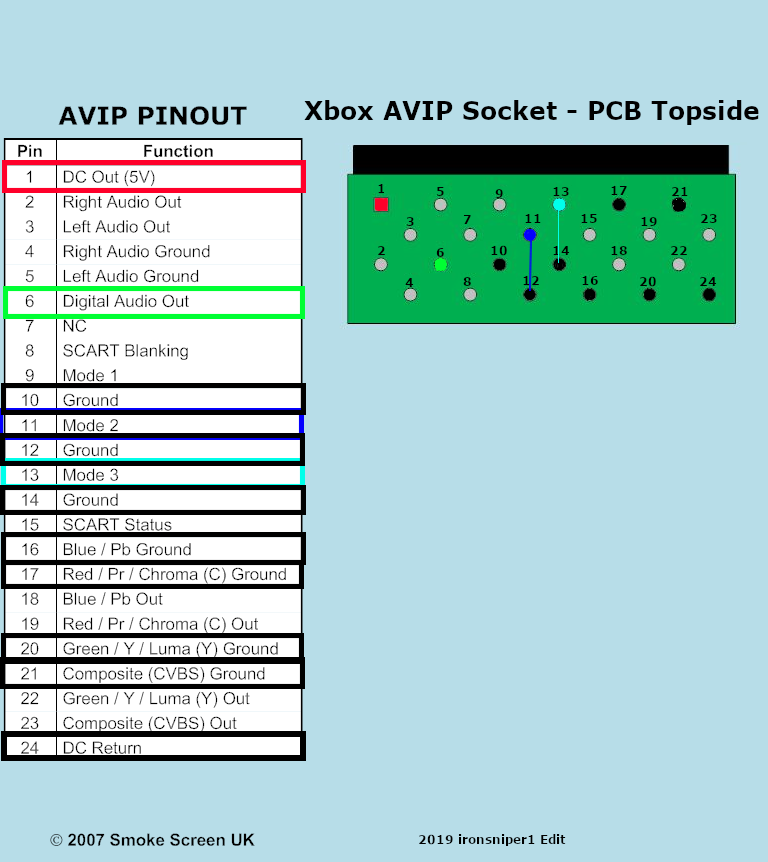
You will need to solder 3 wires (5V, GND, and S/PDIF) to the A/V port holes here. They go to the appropiately labeled pads on the CatponentX PCB. Shielding is not needed.
You will also need to solder two jumpers between the Mode 2/Mode 3 holes, and the adjacent ground points. (Technically, ground is ground and it doesn't matter which ground you use, but it's just convienent to use the adjacent ground pins)
5V = Red
GND = Black
Green = S/PDIF
Mode 2 = Dark Blue (solder to ground)
Mode 3 = Light Blue (solder to ground)
| References | Part Description | Quanity | Price (Total) | Digi-Key |
|---|---|---|---|---|
| C1 | 10uF 16V Aluminum Capacitor | 1 | $0.56 | 493-3913-1-ND |
| C2, C3 | 0.1uF 100V Ceramic Capacitor | 1 | $0.20 | 1276-6840-1-ND |
| R1, R2, R3 | 75 Ohm 1/8W 0805 Resistor | 3 | $0.30 | CR0805-FX-75R0ELFCT-ND |
| R4 | 160 Ohm 1/8W 0805 Resistor | 1 | $0.10 | 118-CR0805-FX-1600ELFCT-ND |
| LED1 | Diffused Red 2V LED | 1 | $0.39 | 754-1901-ND |
| FILTER1 | THS7316DR Analog Video Filter/Amp | 1 | $1.01 | 296-26684-1-ND |
| RCA1 | 3 Component RCA Jacks | 1 | $2.56 | SC1854-ND |
| TOSLINK1 | Optical S/PDIF Transmitter | 1 | N/A | 3185-FCR684208T-ND |
Note: R4 and LED1 are optional if you don't want a power LED.
| Qty | Value | Footprint | References |
|---|---|---|---|
| 4 | Y_IN | TestPoint:TestPoint_Pad_D2.5mm | GND_IN1, Pr_IN1, SPDIF_IN1, VCC_IN1 |
| 3 | R75 | Resistor_SMD:R_0805_2012Metric_Pad1.20x1.40mm_HandSolder | R1, R2, R3 |
| 2 | 0.1uF | Capacitor_SMD:C_0805_2012Metric_Pad1.18x1.45mm_HandSolder | C2, C3 |
| 1 | 10uF | Capacitor_SMD:CP_Elec_5x5.8 | C1 |
| 1 | FCR684208T | CatponentX:FCR684205T | TOSLINK1 |
| 1 | G*** | kibuzzard-630C1A0C | kibuzzard-630C1A0C |
| 1 | G*** | kibuzzard-630D7263 | kibuzzard-630D7263 |
| 1 | G*** | kibuzzard-6303C228 | kibuzzard-6303C228 |
| 1 | G*** | kibuzzard-630E2579 | kibuzzard-630E2579 |
| 1 | G*** | kibuzzard-630C1A19 | kibuzzard-630C1A19 |
| 1 | G*** | kibuzzard-630BAD90 | kibuzzard-630BAD90 |
| 1 | G*** | kibuzzard-6303C288 | kibuzzard-6303C288 |
| 1 | G*** | kibuzzard-630BAD88 | kibuzzard-630BAD88 |
| 1 | G*** | kibuzzard-630D7269 | kibuzzard-630D7269 |
| 1 | G*** | kibuzzard-630C1A27 | kibuzzard-630C1A27 |
| 1 | G*** | kibuzzard-6303C26E | kibuzzard-6303C26E |
| 1 | PJRAN3XIU03X | CatponentX:PJRAN3X1U | RCA1 |
| 1 | Pb_IN | TestPoint:TestPoint_Pad_D2.5mm | Y_IN1 |
| 1 | Pr_IN | TestPoint:TestPoint_Pad_D2.5mm | Pb_IN1 |
| 1 | R160 | Resistor_SMD:R_0805_2012Metric_Pad1.20x1.40mm_HandSolder | R4 |
| 1 | THS7316 | CatponentX:THS7316 | FILTER1 |
| 1 | WP914IDT | LED_THT:LED_D3.0mm | LED1 |
The 28 most common of 34 parts.
Absolucy/CatponentX
An internal mod for the original Xbox that provides high-quality component (YPbPr) output


byrantech/macropad
ZMK oriented embedded RP2040-based 9-key macropad with USB-C, extra GPIO, SWD and select THT components.


miakizz/Videoscope
Board for viewing composite video (PAL, NTSC, or SECAM) on an oscilliscope This is a layout of this circuit by W2AEW


c0pperdragon/C64-Video-Enhancement
Component video modification for the C64 8-bit computer


It measures 65.8 × 55.9 mm and has 2 copper layers, 1.6 mm thick.
34 parts, built around the THS7316D, CR0805-FX-75R0ELF, CL21B104KCFNNNE and UCL1C100MCL1GS. The full list of its parts is on this page, with links to each part's symbol and footprint where PCBKit's library has them.
From the Absolucy/CatponentX repository on GitHub, at the commit this page was made from: the board is CatponentX.kicad_pcb and its schematic CatponentX.kicad_sch. PCBKit opens the board in the browser, with nothing to install.
Its repository states no licence, so its author keeps all rights: ask Absolucy before reusing the design.