2 layers25.4 × 52.1 mm
Atarimod
c0pperdragon/A-VideoBoard
FPGA board to create a component video signal for vintage computers.
14 parts71MIT

 c0pperdragon/A-VideoBoard71
FPGA board to create a component video signal for vintage computers.
A VideoBoard is an open-source printed circuit board by c0pperdragon, from the c0pperdragon/A-VideoBoard repository on GitHub, published under the MIT licence. It is a 2-layer board of 43.2 × 53.3 mm with 75 parts on 68 nets, routed with 721 tracks and 94 vias.
It is built around the 10M02SCE144I7G, THS7316D and LM1117IMPX-3.3. Its parts include 29 resistors, 28 capacitors, 3 inductors and 1 IC. It belongs with the fPGA and programmable logic and retro computing and games boards and the FPGA and CPLD boards of this library.


A small FPGA board with a component video interface to directly drive an analog monitor or TV input. Its main purpose is to create component video / RGB mods of vintage home computers and consoles or to provide video output for hobby projects.
It consists of the purest minimum parts necessary to have a multi-purpose FPGA combined with a simple way to generate a YPbPr signal. After much research I finally settled on a cheap MAX 10 device in a TQFP-144 package which I can solder by hand (barely). The rest of the parts are pretty cheap and quite easy to solder.
To interface any of the vintage systems to the A-Video Board, level shifters are necessary to translate the 5 volt to 3.3 volt for the FPGA input pins. These level shifters can be implemented in a system specific daughter board that can be stacked on top of the A-Video board. Any such interface board can probably be implemented in a simple single-sided wide-pitch PCB that can be even home-etched with some experience.
Currently I have built applications of the A-Video board for
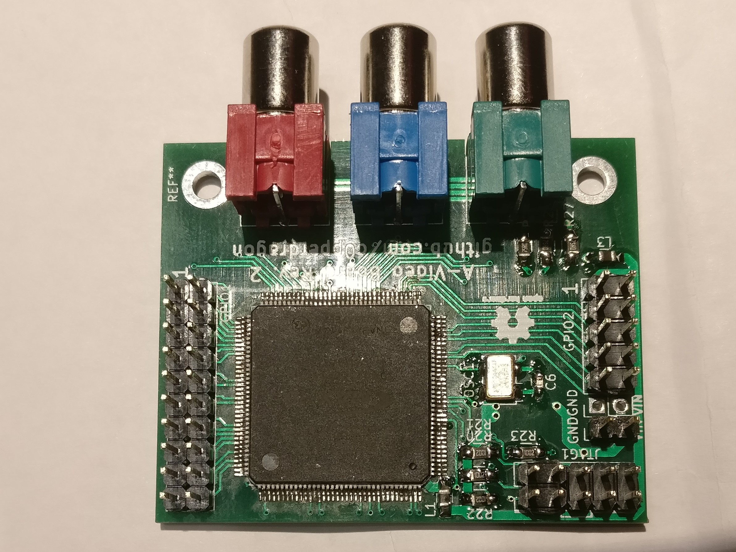
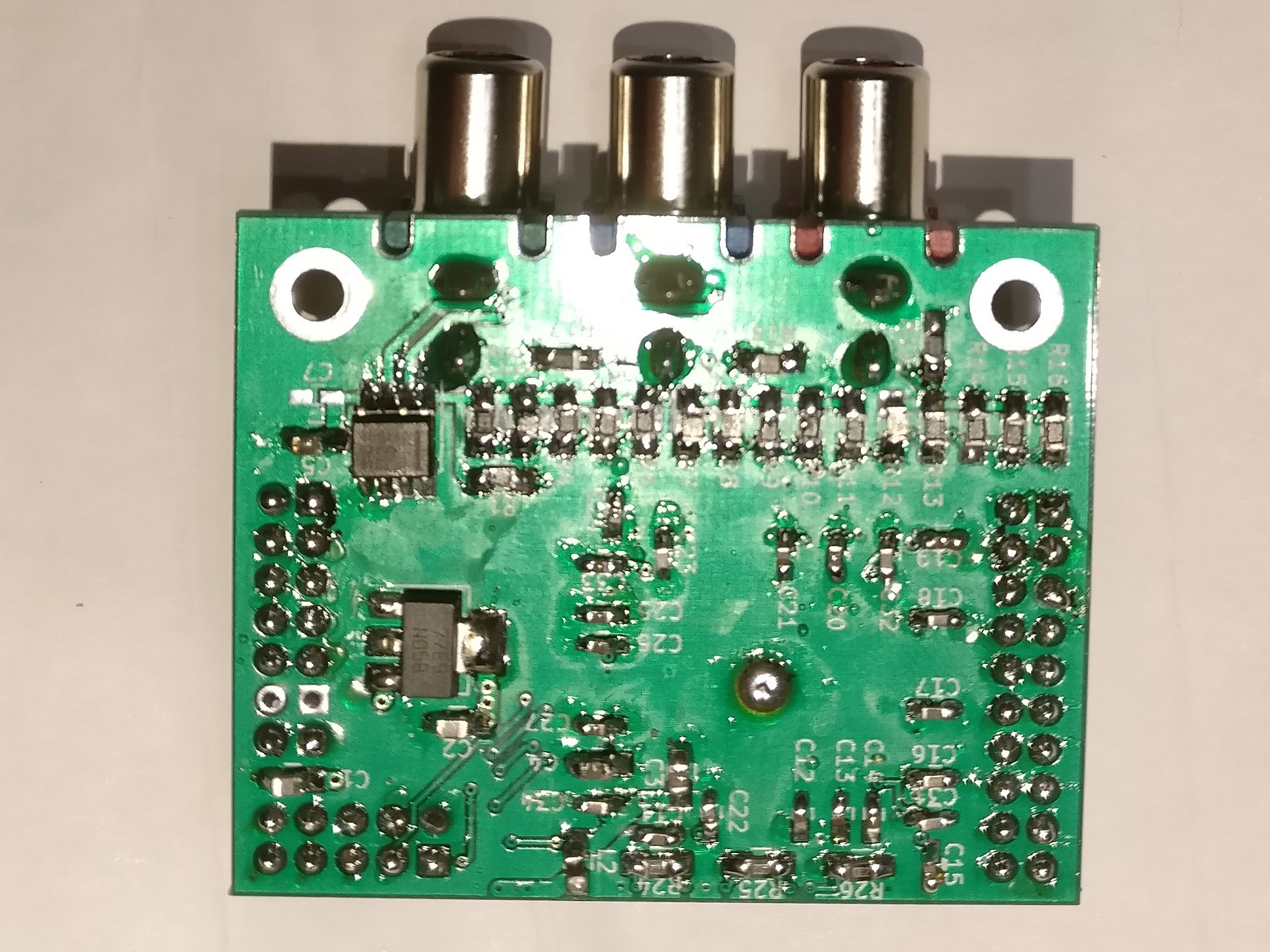
The board has these main parts
and various supporting passive components, mainly decoupling, filtering and pull-ups.
It has the following connectors:
If you plan to use an A-Video board, feel free to contact me for assistance:
reinhard.grafl (at) aon.at
Maybe I will either have some spare PCBs I could send you to populate yourself,
or even provide you with a fully assembled board for the cost of the parts and shipping.
| Qty | Value | Footprint | References |
|---|---|---|---|
| 23 | 100nF | Capacitors_SMD:C_0603_HandSoldering | C11, C12, C13, C14, C15, C16, C17, C18, C19, C20, C21, C22, C23, C24, C25, C26 +7 |
| 7 | 10k | Resistors_SMD:R_0805_HandSoldering | R20, R21, R22, R23, R24, R25, R26 |
| 5 | 10uF | Capacitors_SMD:C_0805_HandSoldering | C1, C2, C3, C4, C5 |
| 3 | 10mH | Capacitors_SMD:C_0805_HandSoldering | L1, L2, L3 |
| 3 | 150 | Resistors_SMD:R_0805_HandSoldering | R17, R18, R19 |
| 3 | 16k | Resistors_SMD:R_0805_HandSoldering | R6, R11, R16 |
| 3 | 1k | Resistors_SMD:R_0805_HandSoldering | R2, R7, R12 |
| 3 | 2k | Resistors_SMD:R_0805_HandSoldering | R3, R8, R13 |
| 3 | 4k | Resistors_SMD:R_0805_HandSoldering | R4, R9, R14 |
| 3 | 75 | Resistors_SMD:R_0805_HandSoldering | R27, R28, R29 |
| 3 | 8k | Resistors_SMD:R_0805_HandSoldering | R5, R10, R15 |
| 3 | BNC | footprints:RCA_JACK | PB1, PR1, Y1 |
| 2 | CONN_02X05 | Pin_Headers:Pin_Header_Straight_2x05_Pitch2.54mm | GPIO2, JTAG1 |
| 1 | 10M02SCE144 | footprints:QFP_144_GND | U2 |
| 1 | 1k1 | Resistors_SMD:R_0805_HandSoldering | R1 |
| 1 | CONM_01x02 | Pin_Headers:Pin_Header_Straight_1x02_Pitch2.54mm | GND |
| 1 | CONN_02X01 | Pin_Headers:Pin_Header_Straight_1x02_Pitch2.54mm | GND |
| 1 | CONN_02X10 | Pin_Headers:Pin_Header_Straight_2x10_Pitch2.54mm | GPIO1 |
| 1 | LFSPXO024957 | Oscillators:Oscillator_SMD_EuroQuartz_XO53-4pin_5.0x3.2mm_HandSoldering | OSC1 |
| 1 | LM1117IMPX-3.3 | TO_SOT_Packages_SMD:SOT-223 | REG1 |
| 1 | THS7316 | Housings_SOIC:SOIC-8_3.9x4.9mm_Pitch1.27mm | AMP1 |
The 72 most common of 75 parts.
c0pperdragon/A-VideoBoard
FPGA board to create a component video signal for vintage computers.

c0pperdragon/A-VideoBoard
FPGA board to create a component video signal for vintage computers.

c0pperdragon/A-VideoBoard
FPGA board to create a component video signal for vintage computers.

c0pperdragon/C64-Video-Enhancement
Component video modification for the C64 8-bit computer

c0pperdragon/ZX-Spectrum-Component-Video
Component video (YPbPr) output for the ZX Spectrum computer


swiszczoo/adat_usb_interface
16-in, 16-out 4x ADAT <=> USB interface supporting USB Audio Class 2.0


c0pperdragon/SIO2SD
An Arduino-based floppy drive emulator for the atari 8 bit computers.


It measures 43.2 × 53.3 mm and has 2 copper layers, 1.6 mm thick.
75 parts, built around the 10M02SCE144I7G, THS7316D and LM1117IMPX-3.3. The full list of its parts is on this page, with links to each part's symbol and footprint where PCBKit's library has them.
From the c0pperdragon/A-VideoBoard repository on GitHub, at the commit this page was made from: the board is board/board.kicad_pcb. PCBKit opens the board in the browser, with nothing to install.
Its repository publishes it under the MIT licence: you may reuse it on that licence's terms (keep the author's notice, and for a copyleft licence share your changes alike).