2 layers61 × 64.1 mm
Rfreplacement
c0pperdragon/C64-Video-Enhancement
Component video modification for the C64 8-bit computer
98 parts286MIT
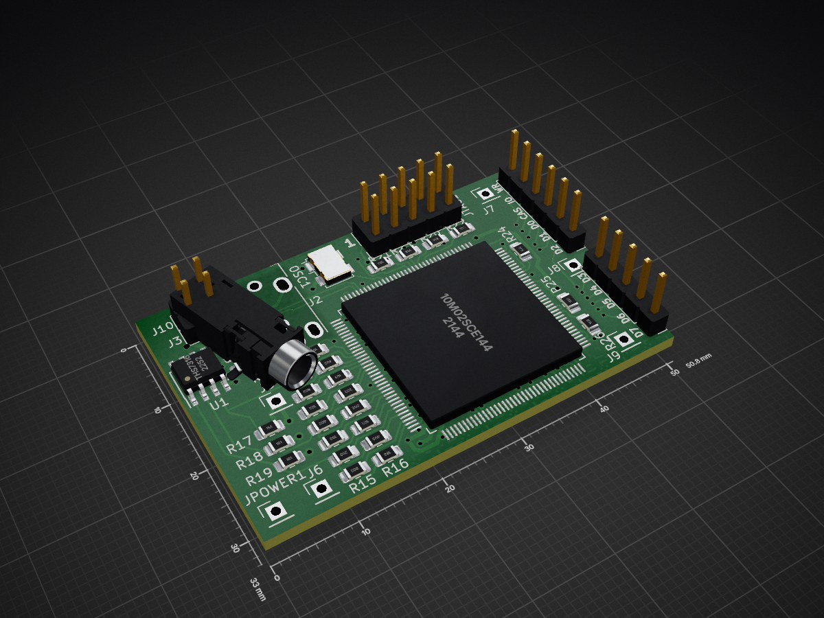
 c0pperdragon/ZX-Spectrum-Component-Video40
Component video (YPbPr) output for the ZX Spectrum computer
ZX Spectrum Component Video is an open-source printed circuit board by c0pperdragon, from the c0pperdragon/ZX-Spectrum-Component-Video repository on GitHub. It is a 2-layer board of 50.8 × 33 mm with 78 parts on 132 nets, routed with 828 tracks and 86 vias.
It is built around the 10M02SCE144I7G, THS7316D and LM1117IMPX-3.3. Its parts include 29 resistors, 28 capacitors, 11 connectors, 4 ICs and 3 inductors. It belongs with the retro computing and games boards and the FPGA and CPLD boards of this library.


Component video (YPbPr) output for the ZX Spectrum computer
The ZX Spectrum in its original form produces a radio frequency signal that can be fed into an analog TV. The quality of this signal is very poor, but this can be improved by a simple modification that will make the ZX Spectrum output a composite video signal instead. While this is actually better, it is nowhere near good. To bring the video quality to the next level, this modification will produce a component video signal (YPbPr) that should be as good as an analog signal can possible get. This video signal can be used either directly with a TV that has a YPbPr input, or it can be passed through a dedicated upscaler device ("Framemeister", "OSSC", etc.) before displaying on an HDMI screen.
This hardware modification is a more compact version of the solution that uses an A-Video board with seperate level shifters. It tries to solve various shortcomings of https://github.com/c0pperdragon/A-VideoBoard/tree/master/zxspectrummod :
The mod board passively listens to various digital data lines through which the ULA communicates with the rest of the main board - specifically the signals CAS,RW,IOREQ and the data bus. This information is processed by the FPGA to figure out what image the ULA intends to display. The FPGA drives a simple 3-channel digital-to-analog converter built from resistors to produce the 3 output voltages of the YPbPr signal. Because the main board runs with 5 volt logic levels and the FPGA can only work with 3.3 volts, a voltage regulator and two input level shifter ICs are necessary (on the bottom side of the mod board).
Output modes can be selected by jumpers or optional switches.
The color palette I am using has slightly softened colors. The original monochromatic colors are just too hard on my eyes especially when viewed on a modern display. I took the platte from [https://lospec.com/palette-list/zx-spectrum] and in my opinion this really looks great.
Installation of the mod requires complete removal of the RF modulator. This also implies that an existing composite video mod will no longer be available. Without further modification the ZX Spectrum will then work with component video output exclusively.
If you need composite video additionally you can wire up an extra connector, as the original analog signals are still being produced by the video output circuit.
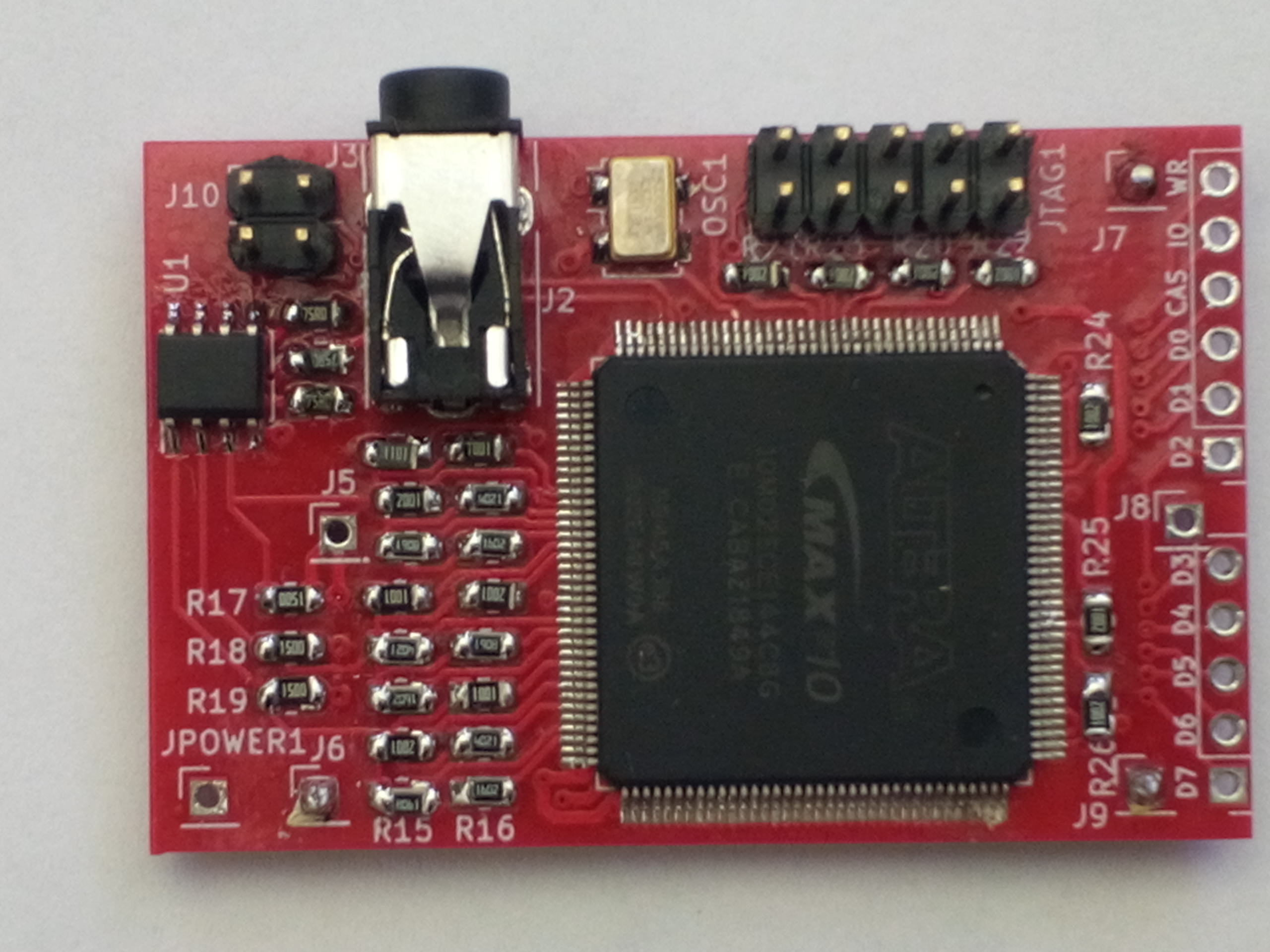
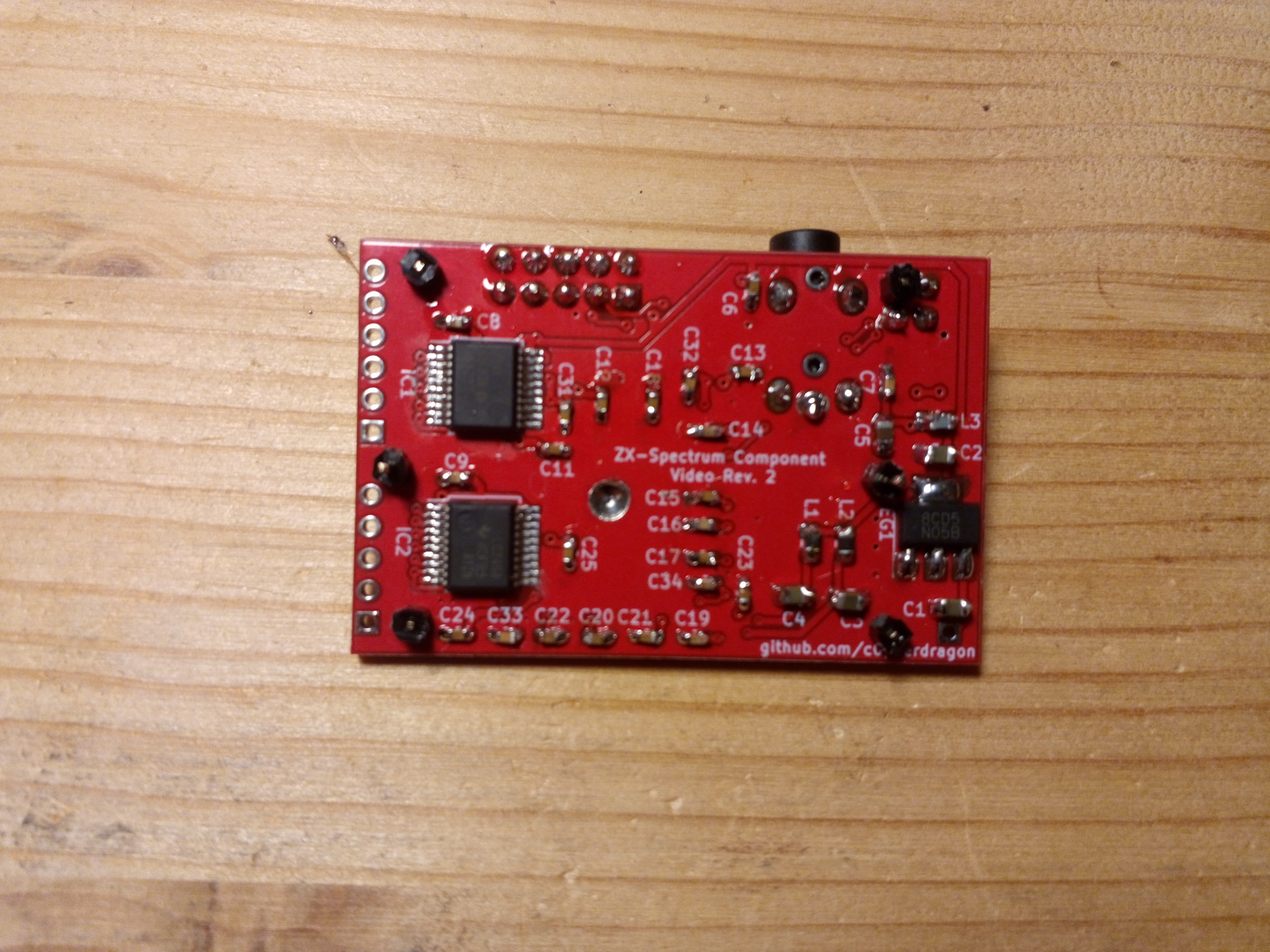

You can switch to 576p (enhanced definition TV - double vertical resolution) by bridging the jumper J10. Likewise you can switch to RGsB output by briding the jumper J3. Both can either be done with a jumper (permenant setting) or an optional external switch. You can do that in whatever way you like - maybe there is even a solution that does not require to modify the case.
The mod uses a small TRRS jack to provide the component video signal. For use with standard cabling, you will need an adapter to break out the 3 lines to individual RCA jacks. Take care to use a cable that has the common ground on the sleeve of the tip-ring-ring-sleeve plug. One possible ready-made product would be: [https://www.delock.de/produkte/S_62499/merkmale.html]
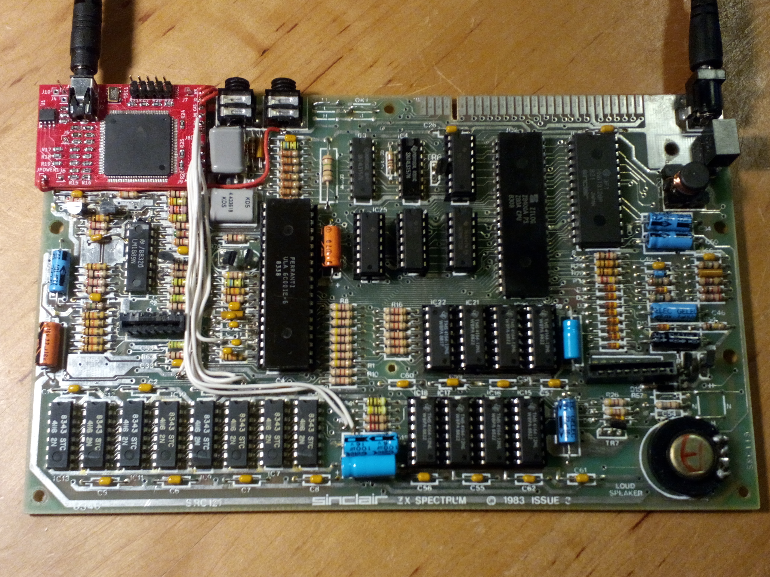
Remove an existing RF modulator completely and remove all the solder from the mounting holes. Put the mod boad in place of the modulator and solder the two mounting pins. These pins will also connect the GND levels. For the following cabling I recommend some single stranded wire that is just thin enough to fit into the various via holes of the main board. Using via holes wherever possible is the least invasive option and is also easily reversible.
+5V power supply must be wired to the JPOWER1 hole of the board. A usable voltage source can be found for example near the headphone jacks. Do not use the power line that was originally driving the RF modulator, as this is comming through some resistor and will not deliver enough current.
The three control signals CAS, IOREQ, WR can best be taken from the backside of the main board directly from the ULA socket pins (see pin_assignment.txt for more details).
Signals D0 to D7 can be taken from various vias through which the data signals are sent on their way between the ULA and the RAM chips. The exact locations may differ with board revision. You may have to probe around with a multimeter to find a conveniently located via for each signal. In the case that you can not find any accessible via, you can also solder your wire directly to the RAM chip (but only as last ressort).
I have provided all my assembled boards to videogameperfection.com for sale. Please have a look at their website first, and if everything is out of stock, you can try to contact me directly at at reinhard.grafl (at) aon.at.
| Qty | Value | Footprint | References |
|---|---|---|---|
| 23 | 100nF | Capacitor_SMD:C_0603_1608Metric_Pad1.05x0.95mm_HandSolder | C11, C12, C13, C14, C15, C16, C17, C18, C19, C20, C21, C22, C23, C24, C25, C31 +7 |
| 7 | 10k | Resistor_SMD:R_0805_2012Metric_Pad1.15x1.40mm_HandSolder | R20, R21, R22, R23, R24, R25, R26 |
| 6 | Conn_01x01_Male | Connector_PinHeader_2.54mm:PinHeader_1x01_P2.54mm_Vertical | J5, J6, J7, J8, J9, JPOWER1 |
| 5 | 10uF | Capacitor_SMD:C_0805_2012Metric_Pad1.15x1.40mm_HandSolder | C1, C2, C3, C4, C5 |
| 3 | 10uH | Capacitor_SMD:C_0805_2012Metric_Pad1.15x1.40mm_HandSolder | L1, L2, L3 |
| 3 | 150 | Resistor_SMD:R_0805_2012Metric_Pad1.15x1.40mm_HandSolder | R17, R18, R19 |
| 3 | 16k | Resistor_SMD:R_0805_2012Metric_Pad1.15x1.40mm_HandSolder | R6, R11, R16 |
| 3 | 1k | Resistor_SMD:R_0805_2012Metric_Pad1.15x1.40mm_HandSolder | R2, R7, R12 |
| 3 | 2k | Resistor_SMD:R_0805_2012Metric_Pad1.15x1.40mm_HandSolder | R3, R8, R13 |
| 3 | 4k | Resistor_SMD:R_0805_2012Metric_Pad1.15x1.40mm_HandSolder | R4, R9, R14 |
| 3 | 75 | Resistor_SMD:R_0805_2012Metric_Pad1.15x1.40mm_HandSolder | R27, R28, R29 |
| 3 | 8k | Resistor_SMD:R_0805_2012Metric_Pad1.15x1.40mm_HandSolder | R5, R10, R15 |
| 2 | Conn_01x02 | Connector_PinHeader_2.54mm:PinHeader_2x01_P2.54mm_Vertical | J3, J10 |
| 2 | LVC245A | Package_SO:SSOP-20_5.3x7.2mm_P0.65mm | IC1, IC2 |
| 1 | 10M02SCE144 | footprints:QFP_144_GND | U2 |
| 1 | 1k1 | Resistor_SMD:R_0805_2012Metric_Pad1.15x1.40mm_HandSolder | R1 |
| 1 | AudioJack4_Ground | footprints:Conrad 4pin audio jack | J2 |
| 1 | CONN_02X05 | Connector_PinHeader_2.54mm:PinHeader_2x05_P2.54mm_Vertical | JTAG1 |
| 1 | Conn_01x05_Male | Connector_PinHeader_2.54mm:PinHeader_1x05_P2.54mm_Vertical | J11 |
| 1 | Conn_01x06_Male | Connector_PinHeader_2.54mm:PinHeader_1x06_P2.54mm_Vertical | J1 |
| 1 | LFSPXO024957 | Oscillator:Oscillator_SMD_EuroQuartz_XO53-4Pin_5.0x3.2mm_HandSoldering | OSC1 |
| 1 | LM1117IMPX-3.3 | Package_TO_SOT_SMD:SOT-223 | REG1 |
| 1 | THS7316 | Package_SO:SOIC-8_3.9x4.9mm_P1.27mm | U1 |
c0pperdragon/C64-Video-Enhancement
Component video modification for the C64 8-bit computer

c0pperdragon/A-VideoBoard
FPGA board to create a component video signal for vintage computers.


swiszczoo/adat_usb_interface
16-in, 16-out 4x ADAT <=> USB interface supporting USB Audio Class 2.0


c0pperdragon/SIO2SD
An Arduino-based floppy drive emulator for the atari 8 bit computers.


It measures 50.8 × 33 mm and has 2 copper layers, 1.6 mm thick.
78 parts, built around the 10M02SCE144I7G, THS7316D and LM1117IMPX-3.3. The full list of its parts is on this page, with links to each part's symbol and footprint where PCBKit's library has them.
From the c0pperdragon/ZX-Spectrum-Component-Video repository on GitHub, at the commit this page was made from: the board is board/board.kicad_pcb. PCBKit opens the board in the browser, with nothing to install.
Its repository states no licence, so its author keeps all rights: ask c0pperdragon before reusing the design.