4 layers21 × 51 mm
Easyduino RP2040
Hanqaqa/Easyduino
Easily dive into different PCB KiCad designs of the most popular microcontroller devboards
65 parts755CERN-OHL-P-2.0

 plinkysynth/miniboard1
fatar tp 9s keyboard scanner with rp2040
Miniboard is an open-source printed circuit board by plinkysynth, from the plinkysynth/miniboard repository on GitHub, published under the CC0-1.0 licence. It is a 2-layer board of 36.7 × 27.7 mm with 46 parts on 62 nets, routed with 505 tracks and 62 vias.
It is built around the RP2040, W25Q16JVUXIQ and XC6206P332MR, with the KT-0603R among its other parts. Its parts include 14 capacitors, 13 resistors, 4 ICs, 4 connectors and 1 diode. It belongs with the RP2040 boards of this library.


August 2026
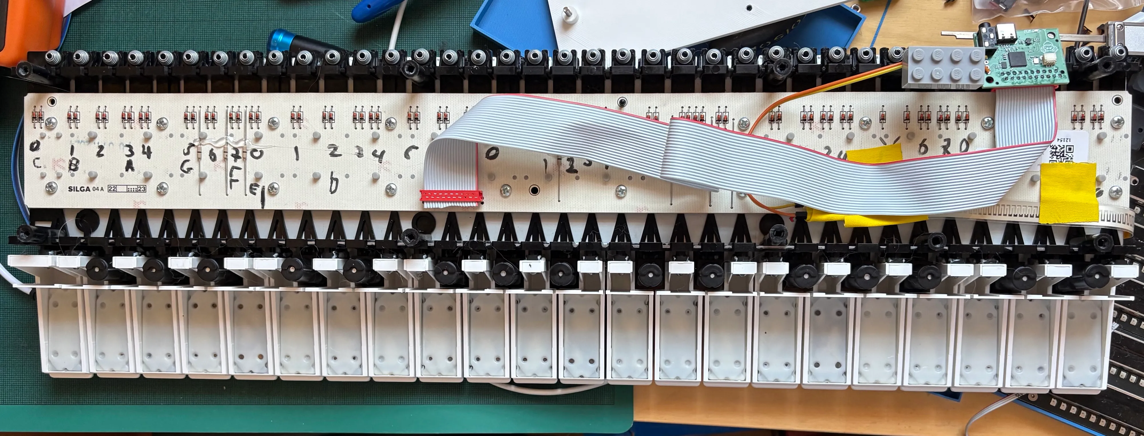
there's no point looking at this project until you are the proud owner of a fatar 9s keybed. probably the 37 key variant.
I got mine at great expense a few years ago from https://enlo-1.com/products/fatar-tp-9s-keyboard but im not sure if they are meant to sell them to us hobbyists? either way it was expensive for what it is! maybe you can find one cheaper somewhere else. I am not affiliated with them in any way, just documenting my build.
forked from my earlier 2024 zacboard project, that included an oled, 2 encoders, and a silly set of i2c slider boards that allowed it to sport more sliders than keys.
im not sure if i ever released that one publically (* i did not), but i was curious about making a super minimal 'fatar keybed and nothing else' the other day, so I stripped everything down, speed-designed a PCB, and re-ordered from JLC. the boards just arrived, they work, I am putting this up on github before thinking too much...
the software just times make/breaks when scanning the keybed, as one must, and uses that to pick a velocity.
it also feeds the aftertouch resistor to ADC0 and uses that to generate aftertouch events.
it sends MIDI messages out on channel 0 on the TRS port and over usb midi.
the pcb has a 3 pin connector for a raspberry pi debug probe
https://www.raspberrypi.com/products/debug-probe/
which I highly recommend for all rp2040 hacking projects. it gives you quick way to flash new software without messing with reset buttons, clean debugging in vscode, watch, breakpoints, etc.
i set this project to use rtt segger style printf, which is THE ONE TRUE WAY but is surprisingly underdocumented in the pico sdk. If you have a probe connected you can see your printf's in vscode via the TERMINAL tab, and its really cheap, and doesnt tie up the USB port or a serial port, nor use any GPIOs. lovely!
power is over usb-c obviously
i did this in a yolo rush, so its a bit rough. ordering your own pcbs, its the usual kicad -> jlcpcb -> yay! I even left the production files checked in, so you could even just upload those straight to JLC. it worked for me, but see the section below on improvements you might want to make before spending money.
all the parts should be readily available via their assembly service.
I accept no responsibility for anything that may come from building this stuff! you're on your own.
the open scad file is for a simple plank to screw onto the keybed and mount the circuit board.
a plank of wood or other material would be nicer.
i screwed it into the keybed with 8 wood screws i found in a cupboard :) M3 or M4 I think they were. the pcb has two m3 holes in it, which I used 2 M3 machine screws and nuts for. the stl/openscad file has holes for these.
i HATE HATE HATE the minimatch connector that fatar uses, but here we are. you need some 20 way ribbon cable to clamp it onto, which requires FORCE which often breaks the fragile plastic. I got the connectors from digikey:
| use | quantity | digikey part | manufacturer | manufacturer part | description |
|---|---|---|---|---|---|
| for the cable... | 2x | A99456CT-ND | TE CONNECTIVITY AMP (VA) | 9-215083-0 | CONN PLUG 20POS IDC 28AWG TIN |
| for the pcb... | 1x | A99465CT-ND | TE CONNECTIVITY AMP (VA) | 9-215079-0 | CONN RCPT 20POS 0.1 TIN PCB |
and standard 28AWG 20 way ribbon cable.
The keybed also has a little flat flex variable resistor. connect two wires to it and solder them to the outer two pins of the 4 pin connector on the pcb. voila, after touch.
i should have connected the last 2 pins to GPIOs. I didn't. as a result you can't scan larger keyboards. If i was ordering from JLCPCB again, I'd hook up those two not connected pins to GPIOs.
the TRS jack for midi is too close to the USB-C. it works, but its close.
obviously it could sprout more connections, encoders, buttons, etc.... but that wasnt the point of this minimalist project.
it would make sense to expose more of the free GPIOs as testpads or connectors or whatnot.
the routing is fine, honest.
released into as liberal a license as I can: CC0...
| Qty | Value | Footprint | References |
|---|---|---|---|
| 8 | 100n | Capacitor_SMD:C_0402_1005Metric | C2, C4, C7, C8, C10, C13, C14, C15 |
| 5 | 1k | Resistor_SMD:R_0402_1005Metric | R4, R5, R7, R8, R9 |
| 4 | 1uf | Capacitor_SMD:C_0402_1005Metric | C1, C3, C9, C11 |
| 4 | 33 | Resistor_SMD:R_0402_1005Metric | R1, R2, R11, R12 |
| 4 | TestPoint | TestPoint:TestPoint_Pad_1.5x1.5mm | TP1, TP2, TP3, TP4 |
| 2 | 10k | Resistor_SMD:R_0402_1005Metric | R10, R13 |
| 2 | 18pf | Capacitor_SMD:C_0402_1005Metric | C5, C6 |
| 2 | 5.1k | Resistor_SMD:R_0402_1005Metric | R3, R6 |
| 2 | LOGO | LOGO | G***, G*** |
| 2 | MountingHole | MountingHole:MountingHole_3.2mm_M3 | H1, H2 |
| 1 | AT | Connector_PinHeader_2.54mm:PinHeader_1x04_P2.54mm_Horizontal | J3 |
| 1 | Black_headphone_jack | easyeda2kicad:AUDIO-TH_PJ-3200 | U4 |
| 1 | CSP-USC16-TR | picoplinky_global:VALCON_CSP-USC16-TR | J1 |
| 1 | Conn_01x03_Pin | Connector_JST:JST_SH_SM03B-SRSS-TB_1x03-1MP_P1.00mm_Horizontal | J2 |
| 1 | Crystal_GND24 | Crystal:Crystal_SMD_2520-4Pin_2.5x2.0mm | Y1 |
| 1 | KT-0603R | easyeda2kicad:LED0603-RD | LED1 |
| 1 | Keyboard | minibed:TE_9-215079-0 | J4 |
| 1 | RP2040 | Package_DFN_QFN:QFN-56-1EP_7x7mm_P0.4mm_EP3.2x3.2mm | U3 |
| 1 | SolderJumper_2_Open | Jumper:SolderJumper-2_P1.3mm_Open_Pad1.0x1.5mm | JP1 |
| 1 | W25Q16JVUXIQ | easyeda2kicad:USON-8_L3.0-W2.0-P0.50-BL-EP | U2 |
| 1 | XC6206P332MR | easyeda2kicad:SOT-23-3_L2.9-W1.6-P1.90-LS2.8-BR | U1 |
It measures 36.7 × 27.7 mm and has 2 copper layers, 1.6 mm thick.
46 parts, built around the RP2040, W25Q16JVUXIQ, XC6206P332MR and KT-0603R. The full list of its parts is on this page, with links to each part's symbol and footprint where PCBKit's library has them.
From the plinkysynth/miniboard repository on GitHub, at the commit this page was made from: the board is hw/miniboard.kicad_pcb and its schematic hw/miniboard.kicad_sch. PCBKit opens the board in the browser, with nothing to install.
Its repository publishes it under the CC0-1.0 licence: you may reuse it on that licence's terms (keep the author's notice, and for a copyleft licence share your changes alike).
Hanqaqa/Easyduino
Easily dive into different PCB KiCad designs of the most popular microcontroller devboards


ymkn/YM60JIS
A JIS layout 60% hot swappable custom mechanical keyboard PCB powered by RP2040.

ymkn/YuTofu
YuTofu is an unofficial compatible PCB for the well-known custom keyboard Tofu60 2.0.


