Skip to the content
PCBKitNew board
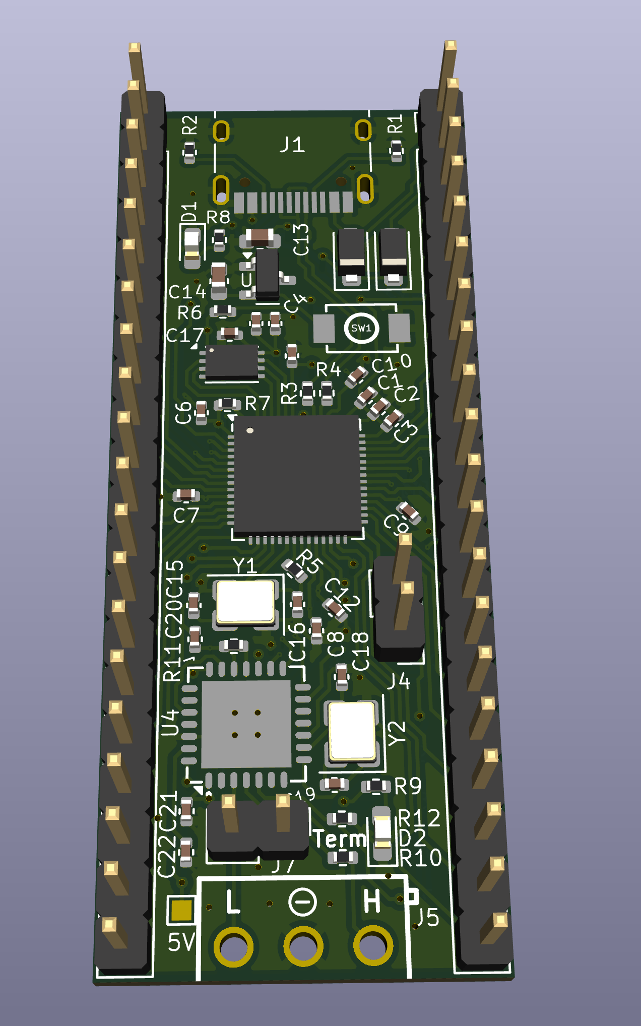
2 layers21 × 51.5 mmPicoCAN, the printed circuit board in 3D

RP2040 based dev board w/built-in CAN controller and transceiver

Size
21 × 51.5 mm
Copper layers
2
Thickness
1.6 mm
Parts
52
Nets
75
Pads
268
Tracks, vias
816, 77
Pours
2
Routed
Yes
KiCad
KiCad 10.0 (file 20260206)
Created
16 Mar 2026
Updated
13 Aug 2026

Overview

PicoCAN is an open-source printed circuit board by AdrianR3, from the AdrianR3/PicoCAN repository on GitHub. It is a 2-layer board of 21 × 51.5 mm with 52 parts on 75 nets, routed with 816 tracks and 77 vias.

It is built around the RP2040, W25Q16JVUXIQ and MBR120VLSFT1G-TP, with the KT-0603R and 19-219/GHC-YR2T1B5Y/3T among its other parts. Its parts include 22 capacitors, 12 resistors, 6 connectors, 4 ICs and 4 diodes. It belongs with the RP2040 boards of this library.

Main components

5

README

README.md

PicoCAN

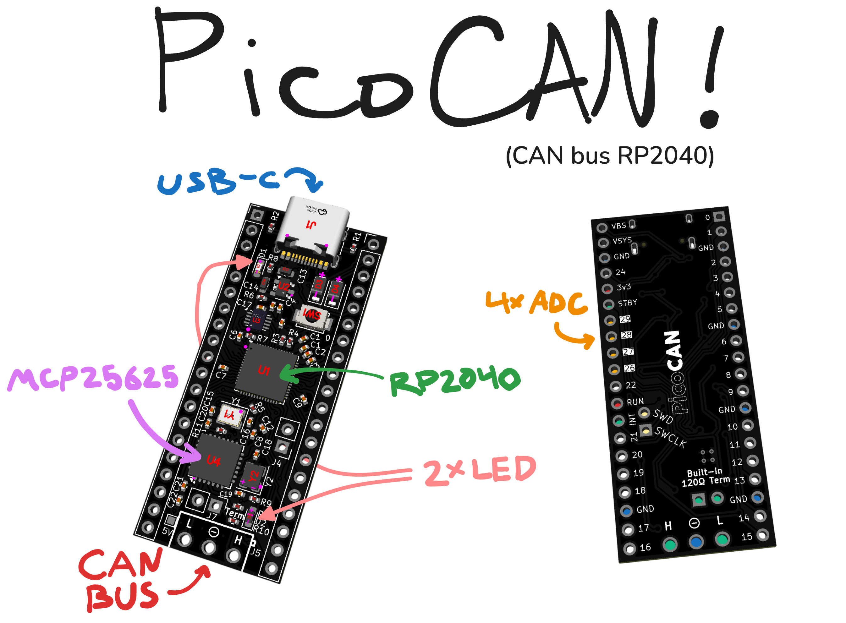
PicoCAN is a custom devboard based on the RP2040 that features a built-in CAN controller and transceiver (the MCP25625 to be exact).

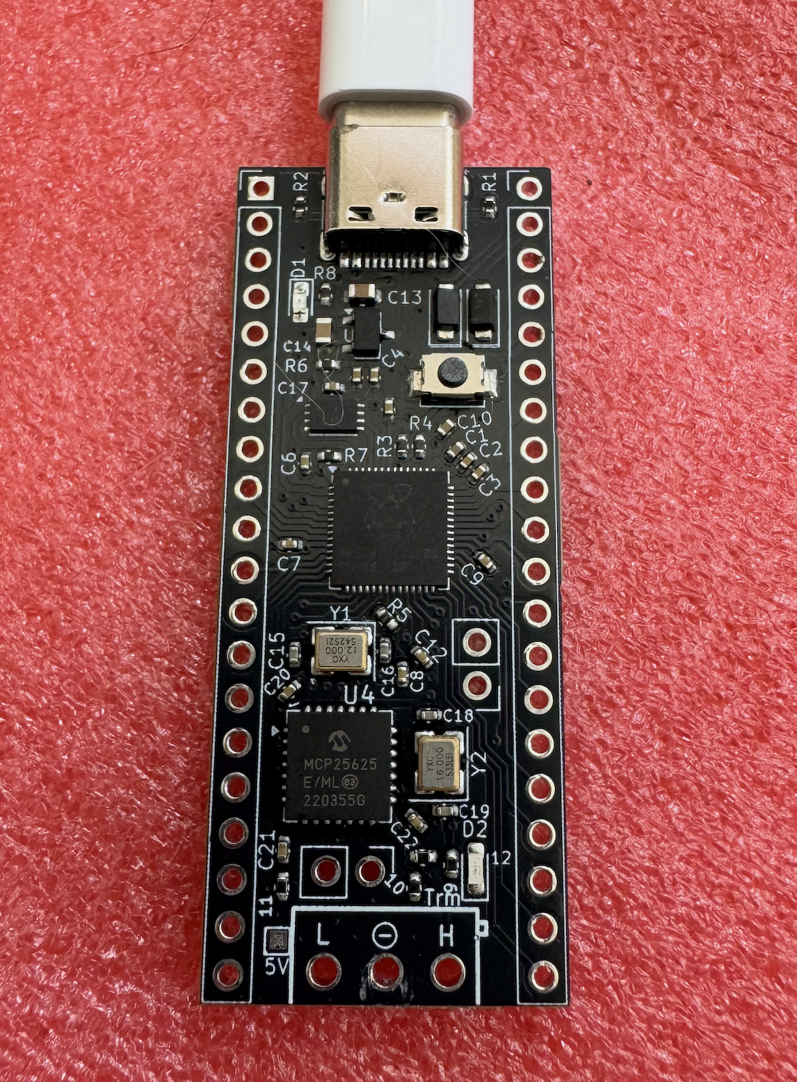
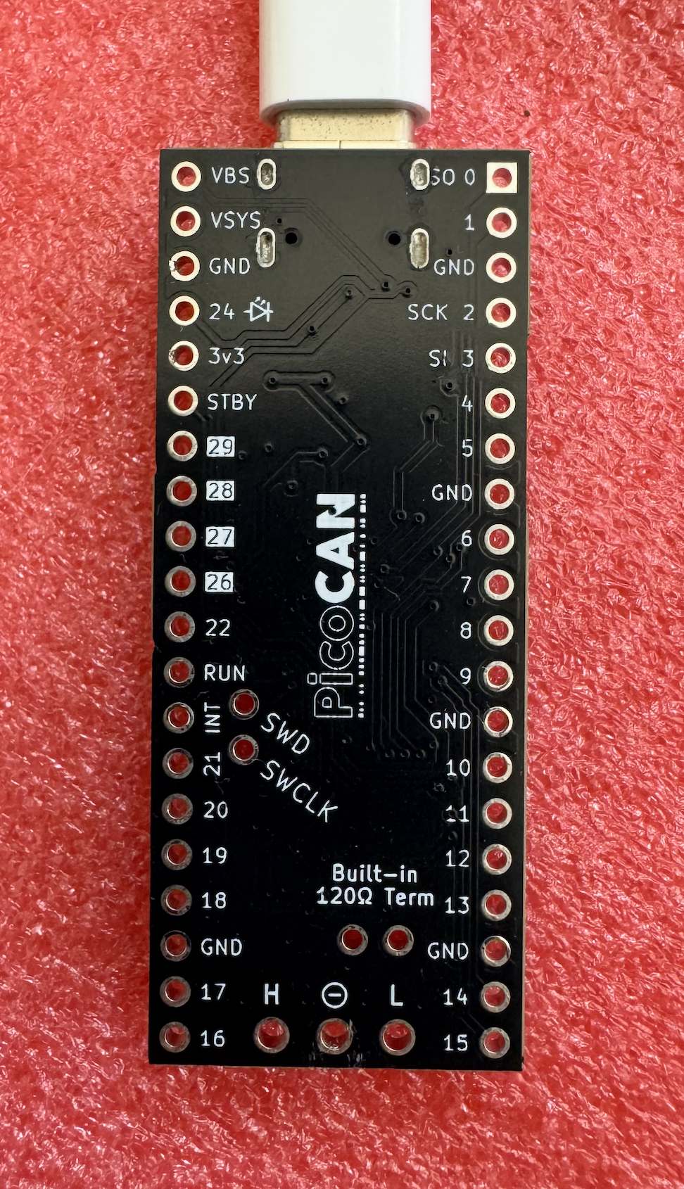
PicoCAN Cover Image Bottom of Assembled PicoCAN

Key Features

  • USB-C connection for easy programming
  • RP2040 based, with the same size as the Pi Pico
  • CAN BUS using MCP25625
    • Built-in 120Ω termination resistor, which can be enabled by bridging the two pins near the CANL pin
    • To use interrupt mode instead of polling for incoming messages, the INT pin can be bridged to the neighboring GPIO21 pin. (See 2nd image above)
  • Support for powering with 5V through VSYS pin
  • 28 usable GPIO pins, including 4 ADC pins
  • Two on-board LEDs (Green and Red)
    • The red LED also shares pin 24 on the board's 2.54mm headers
    • The green LED is not connected to any of the PicoCAN's external pins
      • Internally connected to the RP2040's GPIO25.

Using the CAN bus

To interface with the CAN bus, you can use any library that supports the MCP25625. There are a few examples that use the MCP_CAN library in the ./firmware_examples folder; they are adapted from https://github.com/coryjfowler/MCP_CAN_lib.

More Efficient Than Polling

As shown in the 2nd photo above, the INT pin can be bridged to GPIO21. Pin 21 can be configured as an pullup input, and it will inform the RP2040 when there is a pending CAN bus message to be read.

Building the PicoCAN

The PicoCAN can be ordered from sites like JLCPCB (and optionally assembled too). The KiCAD source files are in ./KiCAD and the production gerber files are in ./KiCAD/prod along with the bom.

This is what JLC PCBA gets you! These don't have the headers soldered on yet. SEE BUILD.md FOR STEPS TAKEN

Manufactured PicoCAN (Top Side) Manufactured PicoCAN (Bottom Side)

Two PicoCANs connected by a (manually) twisted pair

Images

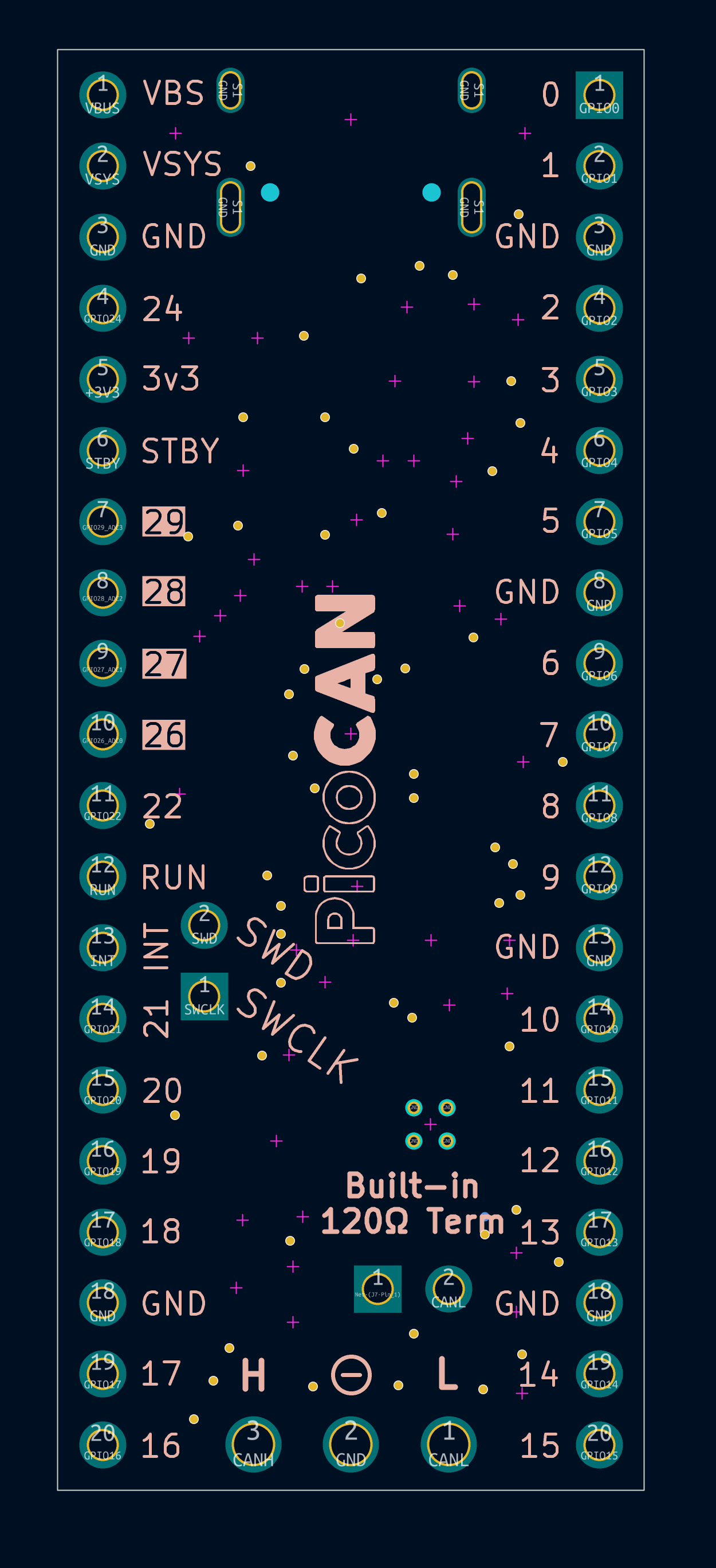
Backside Pinout KiCad Render

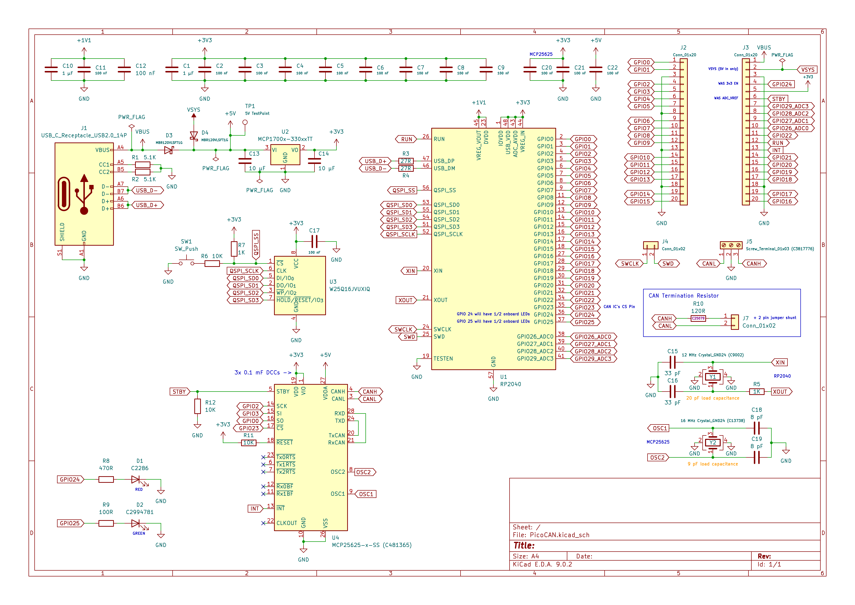
Schematic

PicoCAN Schematic

BOM

Exhaustive PCB component BOM available at ./KiCAD/prod/PicoCAN.csv.

Parts

52
QtyValueFootprintReferences
14100 nFCapacitor_SMD:C_0402_1005MetricC2, C3, C4, C5, C6, C7, C8, C9, C11, C12, C17, C20, C21, C22
310KResistor_SMD:R_0402_1005MetricR6, R11, R12
21 µFCapacitor_SMD:C_0402_1005MetricC1, C10
210 µFCapacitor_SMD:C_0603_1608MetricC13, C14
21KResistor_SMD:R_0402_1005MetricR5, R7
227RResistor_SMD:R_0402_1005MetricR3, R4
233 pFCapacitor_SMD:C_0402_1005MetricC15, C16
25.1KResistor_SMD:R_0402_1005MetricR1, R2
28 pFCapacitor_SMD:C_0402_1005MetricC18, C19
2Conn_01x02Connector_PinHeader_2.54mm:PinHeader_1x02_P2.54mm_VerticalJ4, J7
2Conn_01x20Connector_PinHeader_2.54mm:PinHeader_1x20_P2.54mm_VerticalJ2, J3
2MBR120VLSFT1GDiode_SMD:D_SOD-123FD3, D4
1100RResistor_SMD:R_0402_1005MetricR9
112 MHz Crystal_GND24 (C9002)Crystal:Crystal_SMD_3225-4Pin_3.2x2.5mmY1
1120RResistor_SMD:R_0402_1005MetricR10
116 MHz Crystal_GND24 (C13738)Crystal:Crystal_SMD_3225-4Pin_3.2x2.5mmY2
1470RResistor_SMD:R_0402_1005MetricR8
15V TestPointTestPoint:TestPoint_Pad_1.0x1.0mmTP1
1C2286LED_SMD:LED_0603_1608Metric_Pad1.05x0.95mm_HandSolderD1
1C2994781LED_SMD:LED_0603_1608Metric_Pad1.05x0.95mm_HandSolderD2
1MCP1700x-330xxTTPackage_TO_SOT_SMD:SOT-23U2
1MCP25625x-x-MLPackage_DFN_QFN:QFN-28-1EP_6x6mm_P0.65mm_EP4.25x4.25mmU4
1RP2040Package_DFN_QFN:QFN-56-1EP_7x7mm_P0.4mm_EP3.2x3.2mmU1
1SW_Pusheasyeda2kicad:SW-SMD_L3.9-W3.0-P4.45SW1
1Screw_Terminal_01x03 (C3817776)easyeda2kicad:CONN-TH_3P-P3.50_OSTTE030161J5
1USB_C_Receptacle_USB2.0_14PConnector_USB:USB_C_Receptacle_HRO_TYPE-C-31-M-12J1
1W25Q16JVUXIQPackage_SON:Winbond_USON-8-1EP_3x2mm_P0.5mm_EP0.2x1.6mmU3

Questions

How big is the PicoCAN PCB?

It measures 21 × 51.5 mm and has 2 copper layers, 1.6 mm thick.

What parts does the PicoCAN use?

52 parts, built around the RP2040, W25Q16JVUXIQ, MBR120VLSFT1G-TP and KT-0603R. The full list of its parts is on this page, with links to each part's symbol and footprint where PCBKit's library has them.

Where can I download the PicoCAN KiCad files?

From the AdrianR3/PicoCAN repository on GitHub, at the commit this page was made from: the board is KiCAD/PicoCAN.kicad_pcb and its schematic KiCAD/PicoCAN.kicad_sch. PCBKit opens the board in the browser, with nothing to install.

Can I use the PicoCAN design in my own project?

Its repository states no licence, so its author keeps all rights: ask AdrianR3 before reusing the design.

Similar boards

  • 4 layers44 × 55.1 mmAg ce A7671G card, the printed circuit board in 3D

    Ag ce A7671G card

    Open-Air-Foundation/pcb-module-ce-card

    The CE card adds 4G cellular connectivity (LTE Cat 1) to AirGradient monitors. It can be used in the AirGradient Open Air, the AirGradient ONE, and the Open Air Max.

    106 parts1CC-BY-SA-4.0
  • 2 layers80.5 × 45.1 mmRa5 2022, the printed circuit board in 3D

    Ra5 2022

    pedrohqr/ra5_2022_m

    Base/carrier board for a modular PLC (Programmable Logic Controller): an I/O front-end with no main MCU of its own — sensing and metering peripherals are driven by a separate MCU+LTE modem card that plugs into the…

    154 parts
  • 2 layers30 × 30 mmADXL PCB, the printed circuit board in 3D

    ADXL PCB

    EmielV2002/Inputshaper-PCB

    A PCB to automatically tune your inputshaper settings.

    60 parts2MIT
  • 4 layers29.5 × 23.4 mmStamp RP2040, the printed circuit board in 3D

    Stamp RP2040

    TheContrappostoShop/PICOre

    The PICOre project consist of an ecosystem with stamp module all pin to pin compatible.

    44 parts1
  • 4 layers125 × 70 mm1000base t1-converter, the printed circuit board in 3D

    1000base t1-converter

    TLDSJPWORK/1000base-t1-converter

    学習用 1000BASE-T1 ↔ 1000BASE-T メディアコンバーター

    184 partsCC-BY-4.0
  • 2 layers36.7 × 27.7 mmMiniboard, the printed circuit board in 3D

    Miniboard

    plinkysynth/miniboard

    fatar tp 9s keyboard scanner with rp2040

    46 parts1CC0-1.0
  • 4 layers72.4 × 87.3 mmUi tile kicad, the printed circuit board in 3D

    Ui tile kicad

    arista/ultranetMonitor

    Project for creating an ultranet audio monitor

    64 parts
  • 4 layers53.7 × 21 mmPico WH, the printed circuit board in 3D

    Pico WH

    sabogalc/project-piCo

    Because it should be a crime to release a product with Micro-USB in the 2020s

    93 parts159WTFPL