2 layers58.4 × 50.8 mm

 pimbongaerts/altimeter4
Underwater sonar/USBL interface for photogrammetry surveys. PCB design files and Arduino code.
Altimeter v2 is an open-source printed circuit board by pimbongaerts, from the pimbongaerts/altimeter repository on GitHub. It is a 2-layer board of 48.3 × 123.8 mm with 74 parts on 63 nets, routed with 628 tracks and 92 vias.
It is built around the MAX3232CDR, PCA9306D and PCF8523T, with the TCMT4100 and BK-885 among its other parts. Its parts include 24 resistors, 15 capacitors, 4 ICs, 3 diodes and 3 connectors. It belongs with the interfaces and adapters boards of this library.


Intervalometer with serial interface based on Mega2560 MCU
Current application:
Features:
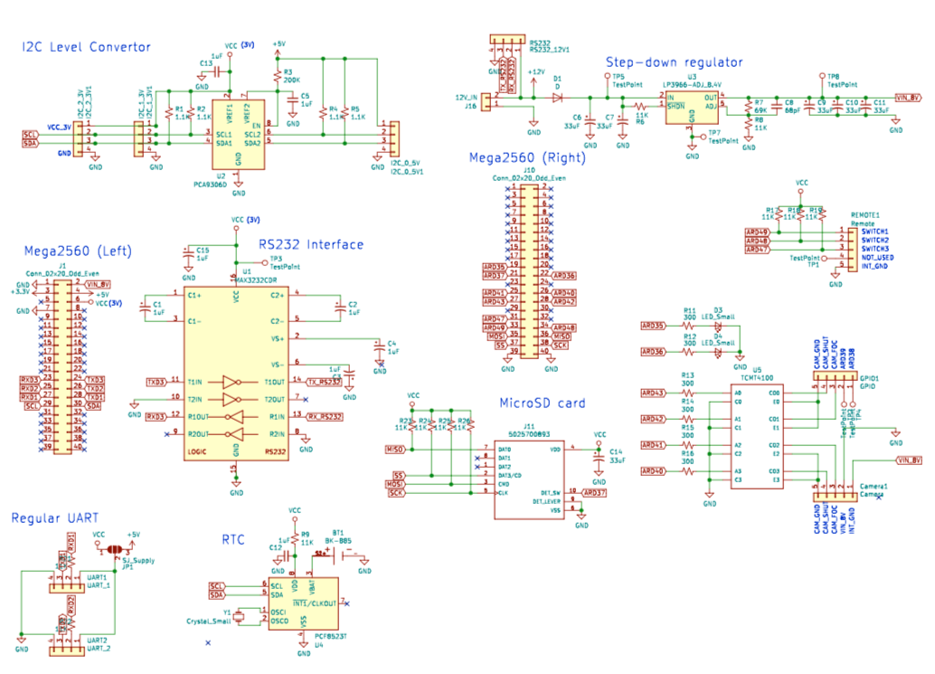
Arduino code (some features are currently commented out)
KiCad PCB file / Bill of materials
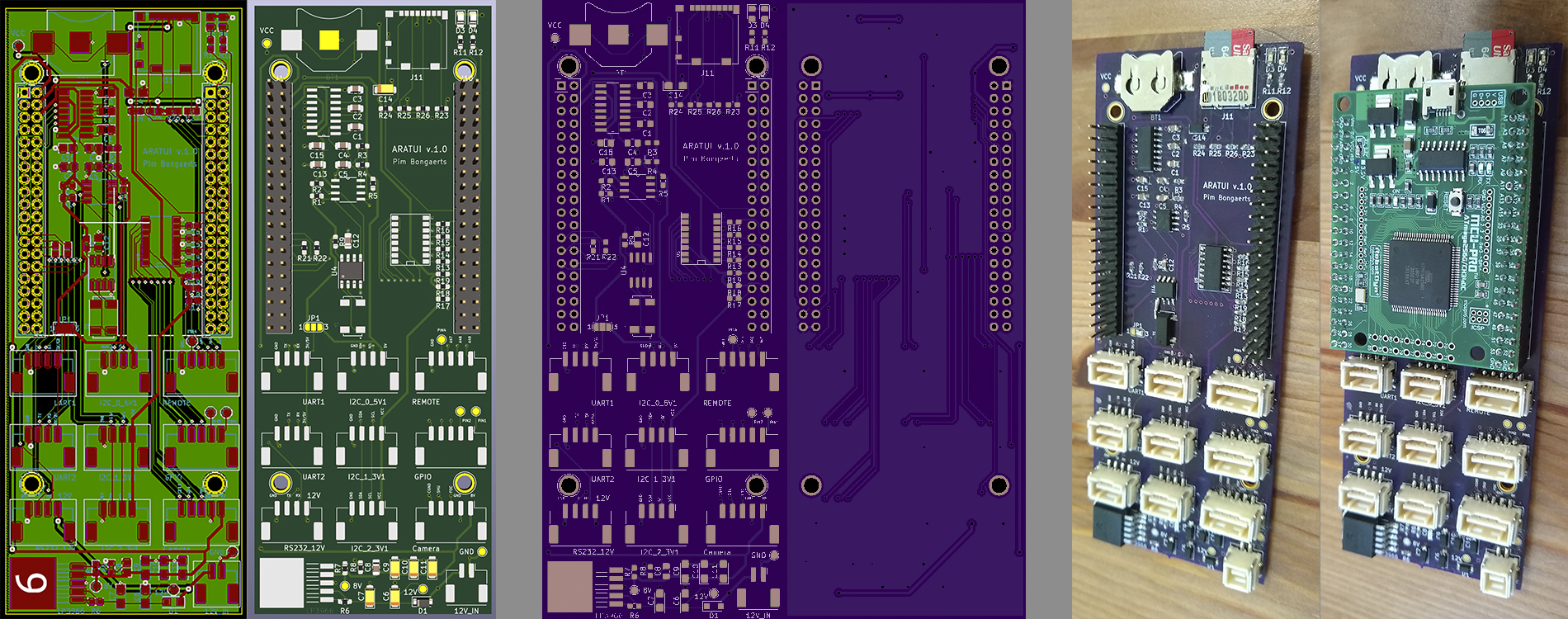
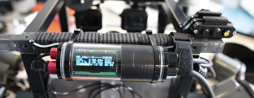
Image shows board installed in a BlueRobotics 2" watertight enclosure, and with a 20x4 OLED display connected. On the left side, there are penetrators for an on/off switch, a BlueRobotics Depth Sensor, and 2 x BlueRobotics Ping Sonar (although on the photo only one connected, hence the "error" on the top-right of the display). On the right side, there is an Ikelite connector to connect with the camera (power and trigger), another Ikelite connector for the 3-button remote (Remora), a penetrator for a cable connecting with the Dive-Xtras Piranha DPV battery, and a penetrator for the cable connecting with the BluePrint Subsea X150 USBL.
Acknowledging John Atkins for all the design advice! Currently working on next iteration with SAMD51 integrated on the board (no external controller board required).
| Qty | Value | Footprint | References |
|---|---|---|---|
| 12 | 11K | Resistor_SMD:R_0603_1608Metric_Pad1.05x0.95mm_HandSolder | R6, R8, R9, R17, R18, R19, R21, R22, R23, R24, R25, R26 |
| 8 | 1uF | Capacitor_SMD:C_0805_2012Metric_Pad1.15x1.40mm_HandSolder | C1, C2, C3, C4, C5, C12, C13, C15 |
| 7 | TestPoint | TestPoint:TestPoint_Pad_D1.5mm | 8V, 12V, GND, PIN1, PIN2, PIN4, VCC |
| 6 | 300 | Resistor_SMD:R_0603_1608Metric_Pad1.05x0.95mm_HandSolder | R11, R12, R13, R14, R15, R16 |
| 6 | 33uF | Capacitor_Tantalum_SMD:CP_EIA-3216-10_Kemet-I_Pad1.58x1.35mm_HandSolder | C6, C7, C9, C10, C11, C14 |
| 4 | 1.1K | Resistor_SMD:R_0603_1608Metric_Pad1.05x0.95mm_HandSolder | R1, R2, R4, R5 |
| 2 | Conn_02x20_Odd_Even | Connector_PinHeader_2.54mm:PinHeader_2x20_P2.54mm_Vertical | J1, J10 |
| 2 | LED_Small | LED_SMD:LED_0805_2012Metric_Pad1.15x1.40mm_HandSolder | D3, D4 |
| 1 | 12V_IN | Connector_Molex:Molex_CLIK-Mate_502443-0270_1x02-1MP_P2.00mm_Vertical | 12V_IN |
| 1 | 200K | Resistor_SMD:R_0603_1608Metric_Pad1.05x0.95mm_HandSolder | R3 |
| 1 | 5025700893 | Connector_Card:microSD_HC_Molex_104031-0811 | J11 |
| 1 | 68pF | Capacitor_SMD:C_0805_2012Metric_Pad1.15x1.40mm_HandSolder | C8 |
| 1 | 69K | Resistor_SMD:R_0603_1608Metric_Pad1.05x0.95mm_HandSolder | R7 |
| 1 | BK-885 | BAT_BK-885 | BT1 |
| 1 | Camera | Connector_Molex:Molex_CLIK-Mate_502443-0570_1x05-1MP_P2.00mm_Vertical | Camera |
| 1 | Crystal_Small | ECS-.327-12:XTAL_ECS-.327-12.5-17X-TR | Y1 |
| 1 | D | Diode_SMD:D_SOD-123F | D1 |
| 1 | GPIO | Connector_Molex:Molex_CLIK-Mate_502443-0570_1x05-1MP_P2.00mm_Vertical | GPIO |
| 1 | I2C_0_5V | Connector_Molex:Molex_CLIK-Mate_502443-0470_1x04-1MP_P2.00mm_Vertical | I2C_0_5V1 |
| 1 | I2C_1_3V | Connector_Molex:Molex_CLIK-Mate_502443-0470_1x04-1MP_P2.00mm_Vertical | I2C_1_3V1 |
| 1 | I2C_2_3V | Connector_Molex:Molex_CLIK-Mate_502443-0470_1x04-1MP_P2.00mm_Vertical | I2C_2_3V1 |
| 1 | LP3966-ADJ_8.4V | LP3966ESX-ADJ_NOPB:TO170P1435X457-5N | LP3966 |
| 1 | MAX3232CDR | MAX3232CDR:SOIC127P600X175-16N | U1 |
| 1 | PCA9306D | PCA9306D_118:SOIC127P600X175-8N | U2 |
| 1 | PCF8523T | Package_SO:SOIC-8_3.9x4.9mm_P1.27mm | U4 |
| 1 | RS232 | Connector_Molex:Molex_CLIK-Mate_502443-0470_1x04-1MP_P2.00mm_Vertical | RS232_12V |
| 1 | Remote | Connector_Molex:Molex_CLIK-Mate_502443-0570_1x05-1MP_P2.00mm_Vertical | REMOTE |
| 1 | SJ_Supply | Jumper:SolderJumper-3_P1.3mm_Open_RoundedPad1.0x1.5mm_NumberLabels | JP1 |
| 1 | TCMT4100 | TCMT4100:SOP-16 | U5 |
| 1 | UART_1 | Connector_Molex:Molex_CLIK-Mate_502443-0470_1x04-1MP_P2.00mm_Vertical | UART1 |
| 1 | UART_2 | Connector_Molex:Molex_CLIK-Mate_502443-0470_1x04-1MP_P2.00mm_Vertical | UART2 |
The 70 most common of 74 parts.
It measures 48.3 × 123.8 mm and has 2 copper layers, 1.6 mm thick.
74 parts, built around the MAX3232CDR, PCA9306D, PCF8523T and TCMT4100. The full list of its parts is on this page, with links to each part's symbol and footprint where PCBKit's library has them.
From the pimbongaerts/altimeter repository on GitHub, at the commit this page was made from: the board is altimeter_v2.kicad_pcb. PCBKit opens the board in the browser, with nothing to install.
Its repository states no licence, so its author keeps all rights: ask pimbongaerts before reusing the design.

rtymk/RT_Open_GPS_Board
Open source RTK GPS board for agricultural applications. LC29HEA GNSS reciever, E22 -900m33s LoRa Radio, 1x RS232 Out, 1x RS232 In, 2x CAN Trasncievers

solmorth/YetAnotherTNC
Modern APRS TNC with Bluetooth and Zigbee connectivity for seamless mobile and IoT integration.

donoghdb/local-zappi
A dedicated hardware implant for Myenergi Zappi V2.x EV Chargers. This project interfaces directly with the Zappi's internal control bus to provide Local MQTT, Home Assistant, and Web Control without relying on the…


risingtideresearch/CAN-Power-Control
CAN device for switching high-current DC loads and reading sensors and switch closures

wojtek-00/HomeAutomation
A modular home automation system built around ESPHome, custom PCB design (KiCad), and 3D-printed enclosures.