


2 layers48.3 × 123.8 mm
Altimeter v2
pimbongaerts/altimeter
Underwater sonar/USBL interface for photogrammetry surveys. PCB design files and Arduino code.
74 parts4

Modern APRS TNC with Bluetooth and Zigbee connectivity for seamless mobile and IoT integration.
Yatnc is an open-source printed circuit board by solmorth, from the solmorth/YetAnotherTNC repository on GitHub. It is a 2-layer board of 55 × 85 mm with 44 parts on 53 nets, routed with 209 tracks and 130 vias.
It is built around the MAX3232CDR and BC547. Its parts include 12 capacitors, 10 resistors, 5 diodes, 5 connectors and 2 transistors. It belongs with the radio and wireless boards of this library.
Zephyr firmware (and, eventually, a companion PCB) for a nRF52840 Pro Micro board that turns a phone's Bluetooth connection into a packet radio TNC. Depending on how three GPIO pins are strapped at boot, the board acts as a transparent UART↔BLE bridge, a real AX.25/KISS TNC driving 1200 baud Bell 202 AFSK audio (with optional FX.25 FEC), an AX.25 digipeater, or a standalone GPS APRS tracker that beacons its position with no phone attached.
Early stage. This has not been widely field-tested — one unit rides in the author's car and works there, but it hasn't been validated across different radios, conditions, or by other users. Treat it as a hobby project that works, not a hardened product.
No app or phone-side code lives in this repo — this is the board (and PCB) side only. Anything that speaks BLE Nordic UART Service (NUS) and either raw KISS or TNC2 monitor lines can talk to it; see Phone app below.
Cheap handheld radios generally don't have a KISS/TNC mode, and dedicated TNC hardware is either bulky or costs more than the radio. This is a ~$10 nRF52840 board wired to a radio's mic/speaker/PTT lines, doing the AFSK modem and AX.25 framing in software, with a phone or laptop over BLE instead of a serial cable.
Primary target: Yaesu FTM510. The board's connector is designed to match the FTM510's mic/data jack. The FTM400 works out of the box — same connector, same signals. Any other radio that can be driven by its mic/speaker/PTT lines can work too, via a custom audio interface cable (not covered by this repo — just the pins on the nRF52840 side).
Board: Pro Micro nRF52840 (or any nice!nano-bootloader-compatible clone,
promicro_nrf52840 in Zephyr).
PCB design files and bill of materials live under pcb/ (yatnc.kicad_sch, yatnc.kicad_pcb, yatnc.csv).
| PCB 3D Render | PCB Editor |
|---|---|
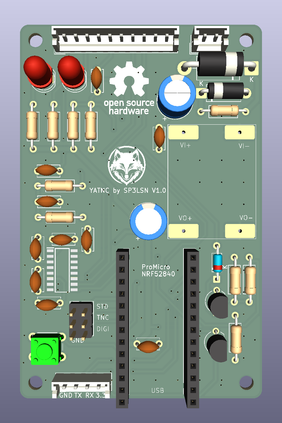 | 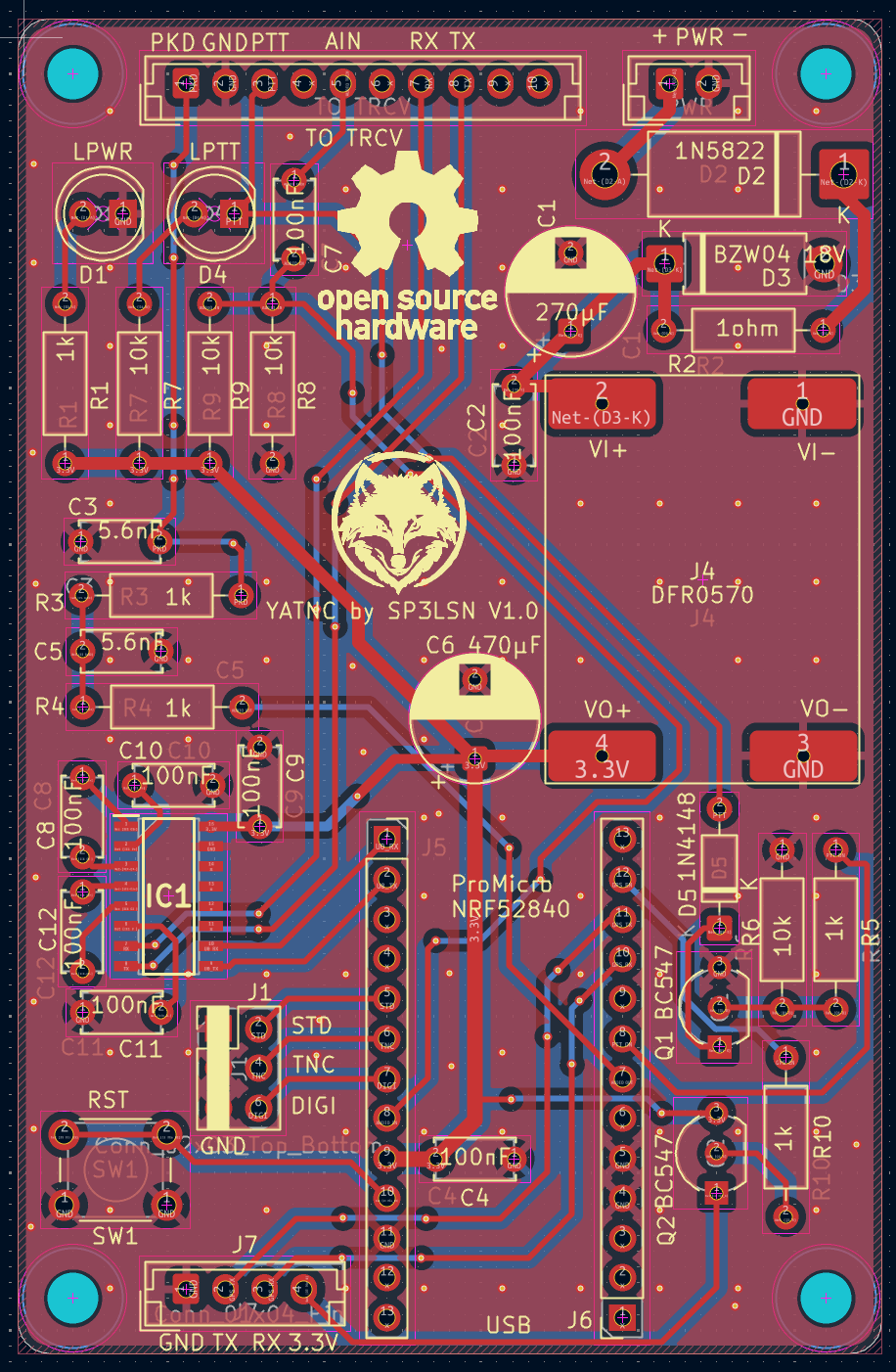 |
| Pin | DT node | Function | Notes |
|---|---|---|---|
| 9, 10 (P0.09/P0.10) | uart0 | Radio RS232 (APRS data) | Level-shifted through an onboard MAX3232 to true RS-232 (±12V). Primary use: the FTM510/FTM400's own built-in APRS packet decoder outputs RS232 here in BRIDGE mode. Also works with other serial-speaking radios/modems that expect a native protocol. Never touched by firmware for anything else. |
| 31 (P0.31) | zephyr,user io-channel | RX audio in | ADC (AIN7), sampled at 9600 Hz for the AFSK demodulator. |
| 20 (P0.20) | &pwm0_default | TX audio out | Hardware PWM carrier, low-pass filtered externally into an analog tone. |
| 22 (P0.22) | ptt_pin | PTT out | Active-high. |
| 2 (P0.02) | mode_pin | Mode select | Pull-up, active-low. Grounded → PACKET_TNC. |
| 29 (P0.29) | digi_pin | Digipeater select | Pull-up, active-low. Grounded → DIGIPEATER (overrides pin 2). |
| P1.15 | standalone_pin | Standalone GPS select | Pull-up, active-low. Grounded → STANDALONE (overrides pins 2 and 29). |
| P0.11 / P1.00 | uart1 | GPS NMEA in | 9600 baud, TX / RX respectively (the GPS module's RX / TX). Only used in STANDALONE mode. |
| P1.04 | gps_enable_pin | GPS power enable | Active-high, pulled down. Driven high at boot in STANDALONE mode (unless a fixed position is configured). |
[!IMPORTANT]
- RS-232 voltage levels (±12V): The serial lines on the 10-pin JST connector (
TO TRCV) are true RS-232 (±12V) driven by the onboard MAX3232 transceiver, not 3.3V or 5V TTL. Do not connect them directly to logic-level UART pins!- RX / TX crossover: The RS-232 RX and TX lines must be crossed between the board's 10-pin JST connector and the radio (Board TX → Radio RX, Board RX → Radio TX).
| Pin | Net | Function / Description |
|---|---|---|
| 1 | PKD | TX Packet Audio (from PWM filter) |
| 2 | GND | Ground |
| 3 | PTT | PTT output |
| 4 | NC | Unconnected |
| 5 | AUDIO TRCV | RX Audio (to ADC demodulator) |
| 6 | NC | Unconnected |
| 7 | RX | RS-232 RX (±12V, connect to Radio TX — crossed) |
| 8 | TX | RS-232 TX (±12V, connect to Radio RX — crossed) |
| 9 | NC | Unconnected |
| 10 | NC | Unconnected |
Generated from KiCad BOM (pcb/yatnc.csv):
| Designator | Value / Part | Qty | Description |
|---|---|---|---|
| C1 | 270µF 35V | 1 | Polarized electrolytic capacitor |
| C2, C4, C7, C8, C9, C10, C11, C12 | 100nF | 8 | Ceramic disc capacitor |
| C3, C5 | 5.6nF | 2 | Ceramic disc capacitor |
| C6 | 470µF 10V | 1 | Polarized electrolytic capacitor |
| D1 | LPWR | 1 | Power indicator LED (5mm) |
| D2 | 1N5822 | 1 | Schottky diode (3A, 40V) |
| D3 | BZW04 18V | 1 | TVS transient voltage suppressor diode |
| D4 | LPTT | 1 | PTT indicator LED (5mm) |
| D5 | 1N4148 | 1 | High-speed switching diode |
| IC1 | MAX3232CDR | 1 | 3.3V/5V RS-232 transceiver (SOIC-16) |
| J1 | Conn_02x03_Top_Bottom | 1 | 2×3 pin header (2.54mm pitch) |
| J4 | DFR0570 | 1 | DFRobot DFR0570 DC-DC buck converter module |
| J5, J6 | Conn_01x13_Socket | 2 | 1×13 female socket headers (for Pro Micro nRF52840) |
| J7 | Conn_01x04_Pin | 1 | JST-EH 4-pin vertical header (2.50mm pitch) |
| PWR | Conn_01x02_Socket | 1 | JST-EH 2-pin vertical power connector (2.50mm pitch) |
| Q1, Q2 | BC547 | 2 | NPN bipolar junction transistor (TO-92) |
| R1, R3, R4, R5, R10 | 1k | 5 | Axial resistor 1kΩ (DIN0207) |
| R2 | 1ohm | 1 | Axial resistor 1Ω (DIN0207) |
| R6, R7, R8, R9 | 10k | 4 | Axial resistor 10kΩ (DIN0207) |
| SW1 | RST | 1 | Tactile push button switch (6mm) |
| TO TRCV | JST | 1 | JST-EH 10-pin vertical connector (to transceiver) |
[!IMPORTANT]
- RS-232 voltage levels (±12V): The serial lines on the 10-pin JST connector (
TO TRCV) are true RS-232 (±12V) driven by the onboard MAX3232 transceiver, not 3.3V or 5V TTL. Do not connect them directly to logic-level UART pins!- RX / TX crossover: The RS-232 RX and TX lines must be crossed between the board's 10-pin JST connector and the radio (Board TX → Radio RX, Board RX → Radio TX).
| Pin | Net | Function / Description |
|---|---|---|
| 1 | PKD | TX Packet Audio (from PWM filter) |
| 2 | GND | Ground |
| 3 | PTT | PTT output |
| 4 | NC | Unconnected |
| 5 | AUDIO TRCV | RX Audio (to ADC demodulator) |
| 6 | NC | Unconnected |
| 7 | RX | RS-232 RX (±12V, connect to Radio TX — crossed) |
| 8 | TX | RS-232 TX (±12V, connect to Radio RX — crossed) |
| 9 | NC | Unconnected |
| 10 | NC | Unconnected |
Generated from KiCad BOM (pcb/yatnc.csv):
| Designator | Value / Part | Qty | Description |
|---|---|---|---|
| C1 | 270µF 35V | 1 | Polarized electrolytic capacitor |
| C2, C4, C7, C8, C9, C10, C11, C12 | 100nF | 8 | Ceramic disc capacitor |
| C3, C5 | 5.6nF | 2 | Ceramic disc capacitor |
| C6 | 470µF 10V | 1 | Polarized electrolytic capacitor |
| D1 | LPWR | 1 | Power indicator LED (5mm) |
| D2 | 1N5822 | 1 | Schottky diode (3A, 40V) |
| D3 | BZW04 18V | 1 | TVS transient voltage suppressor diode |
| D4 | LPTT | 1 | PTT indicator LED (5mm) |
| D5 | 1N4148 | 1 | High-speed switching diode |
| IC1 | MAX3232CDR | 1 | 3.3V/5V RS-232 transceiver (SOIC-16) |
| J1 | Conn_02x03_Top_Bottom | 1 | 2×3 pin header (2.54mm pitch) |
| J4 | DFR0570 | 1 | DFRobot DFR0570 DC-DC buck converter module |
| J5, J6 | Conn_01x13_Socket | 2 | 1×13 female socket headers (for Pro Micro nRF52840) |
| J7 | Conn_01x04_Pin | 1 | JST-EH 4-pin vertical header (2.50mm pitch) |
| PWR | Conn_01x02_Socket | 1 | JST-EH 2-pin vertical power connector (2.50mm pitch) |
| Q1, Q2 | BC547 | 2 | NPN bipolar junction transistor (TO-92) |
| R1, R3, R4, R5, R10 | 1k | 5 | Axial resistor 1kΩ (DIN0207) |
| R2 | 1ohm | 1 | Axial resistor 1Ω (DIN0207) |
| R6, R7, R8, R9 | 10k | 4 | Axial resistor 10kΩ (DIN0207) |
| SW1 | RST | 1 | Tactile push button switch (6mm) |
| TO TRCV | JST | 1 | JST-EH 10-pin vertical connector (to transceiver) |
The firmware selects one of four modes at boot (and re-checks live on every packet) by reading the mode-select, digipeater-select and standalone-select pins above. There is no software switch — the mode is purely hardware-strapped, and the pins are read fresh on every packet, so mode can in principle change at runtime by re-wiring the straps (no latching).
Resolution order (mode_select_get_current() in src/mode_select.c):
standalone_pin grounded → STANDALONEdigi_pin grounded → DIGIPEATERmode_pin grounded → PACKET_TNCA transparent, byte-for-byte serial bridge between the radio's RS232 (UART0) and the phone app over BLE (NUS). No AX.25/KISS parsing, no AFSK, no PTT — just raw bytes both directions.
This is primarily for FTM510/FTM400 radios in their own native APRS mode: the radio decodes AFSK itself and emits packets over RS232, and this mode just relays that (and any outgoing data) to/from the phone app. It also works with any other radio/modem that expects to speak its own native serial protocol (AT commands, firmware passthrough, etc.) rather than doing AX.25 packet radio in this firmware.
uart_isr (main.c) collects UART0 RX bytes into a ring
buffer; 50ms after the line goes idle, process_uart_to_ble() sends
whatever accumulated straight out over BLE notify.nus_received() queues whatever the app wrote straight to
the TX queue; the TX thread writes it byte-by-byte to UART0 via
uart_poll_out().mode_pin grounded)A real AX.25 KISS TNC. The app talks AX.25/KISS over BLE; the radio side is driven as 1200 baud Bell 202 AFSK audio (with optional FX.25 forward error correction), not raw serial.
App → Radio (TX), in tnc_process_ble_bytes():
FEND ... FEND) is only acted on once its closing FEND has actually
arrived — a frame split across several BLE writes (common: phones write
in ~20-byte ATT chunks before MTU negotiation) is reassembled correctly
before anything is sent.SP3LSN-9>APVEC0,WIDE1-1,WIDE2-1:!5227.76N/01654.03E>comment. If nothing
KISS-decodes within 250ms of the app going idle, tnc_send_raw_frame()
tries ax25_parse_monitor() on the accumulated bytes; on success it
builds a real binary AX.25 UI frame (proper shifted-ASCII addresses,
control/PID, FCS) instead of transmitting the raw text. If it doesn't
parse either way, the bytes are assumed to already be a raw AX.25 frame
and sent as-is.FEND byte appears in non-KISS app data (e.g. a Latin-1
accented character in an APRS comment happens to be 0xC0) and never
gets a matching closing FEND, the KISS decoder used to wedge itself
in-frame forever, silently swallowing everything after it. It now
self-resets after the same 250ms idle window instead.AFSKModulator, with
FX.25 RS(255,239) wrapping if enabled via audio_tx_set_fx25(true) —
off by default, no live control path wired to it yet), the waveform is
played out on pin 20 via the nRF52840's hardware PWM, then PTT unkeys.Radio → App (RX), two independent sources feed the same BLE output:
AFSKDemodulator (bandpass filter → frequency discriminator
→ DPLL bit recovery → HDLC flag/destuff, with an FX.25 correlation-tag
correlator running in parallel that transparently Reed-Solomon-corrects a
frame if the sender wrapped it in FX.25). A decoded frame is KISS-wrapped
and sent over BLE.tnc_process_radio_bytes() decodes and forwards those the
same way.digi_pin grounded, overrides mode_pin)Everything PACKET_TNC does, plus: every frame heard on the radio is checked
for an un-repeated WIDEn-N/DIGI hop in its path
(digipeat_process_frame()). If found, the hop's SSID is decremented (H-bit
set once it reaches 0, marking it used) and the frame is re-encoded and
re-transmitted back out over radio — a standard WIDEn-N digipeater. The frame
is forwarded to the BLE app either way, repeated or not, so the app sees
everything heard on the channel.
standalone_pin grounded, overrides the other two)A GPS APRS tracker. The board beacons its position over the radio on a timer, with no phone needed. Otherwise it behaves like PACKET_TNC (the BLE app can still connect, send frames, and change settings).
gps_enable_pin) and reads NMEA from uart1. $GPGGA/$GNGGA sentences
are parsed for fix state and position. The first fix starts the beacon; it
then repeats every BEACON seconds while the fix is held, using the most
recent position. No fix (or fix lost) → nothing is transmitted.SET FIXEDPOS=ON (and both LAT/LON set) the
GPS module is never powered or touched. The stored coordinates are beaconed
on the same interval, starting once the TX pipeline is up. Handy indoors or
with no GPS fitted. Until both coordinates are set, nothing is sent.!DDMM.hhN/DDDMM.hhE> + comment)
from your callsign to APRS, primary-table car symbol (/>), sent through the
normal TX path (PTT → AFSK → PWM).Callsign, beacon interval, comment and fixed position are set at runtime with
single-line ASCII commands sent as KISS command 0x06 (KISS_CMD_SETHARDWARE)
over BLE. Each command is applied immediately, saved to flash, and answered
with a KISS 0x06 frame carrying the reply text. Errors are reported in the
reply (ERR ...), never as a dropped connection. Settings survive reboots.
| Command | Effect | Default |
|---|---|---|
SET CALL=N0CALL-9 | Source callsign for beacons | N0CALL |
SET BEACON=120 | Beacon interval in seconds (clamped to 10–3600) | 60 |
SET COMMENT=text | Beacon comment (truncated to 32 chars) | empty |
SET FIXEDPOS=ON|OFF | Beacon a stored position instead of using GPS | OFF |
SET LAT=52.4627 / SET LON=16.9005 | Fixed position, decimal degrees | unset |
GET | Reply with all current values |
The settings live in a 32 KiB NVS partition at 0x90000 (see app.overlay),
deliberately clear of the UF2 bootloader. The BLE device name is YATNC.
audio_tx_set_fx25, code
only).SET/GET config commands are not yet exposed in any phone app; send
them yourself as KISS 0x06 frames.Developed and tested against aprsvector (also by the author) — that's the reference app for this firmware and the one to reach for first.
More generally, anything that speaks BLE Nordic UART Service (NUS) and either raw KISS or TNC2 monitor lines should work (most Android APRS apps fit this description), but only aprsvector has actually been tested against this firmware.
./build.shFirst run creates a .venv, pulls a Zephyr workspace into zephyrproject/
(via west), and builds for promicro_nrf52840. Later runs reuse both, so
they're much faster. Pass anything after the script name straight through to
west build if you need non-default args:
./build.sh -b promicro_nrf52840 --pristineIf no usable Zephyr SDK is found (it looks in .zephyr-sdk/,
~/zephyr-sdk-*, /opt/zephyr-sdk-*, etc, and checks that CMake and the ARM
compiler are actually present), the script downloads a minimal one into
.zephyr-sdk/ and sets up the arm-zephyr-eabi toolchain. Set
ZEPHYR_SDK_INSTALL_DIR to use your own instead.
Output is build/zephyr/zephyr.uf2. To flash: double-tap the board's reset
button to drop into the UF2 bootloader (it'll show up as a USB drive), then
copy the file over. Boards need the nice!nano / Adafruit UF2 bootloader
already installed.
Pushing a version tag (1.2.3 or v1.2.3) triggers
.github/workflows/release.yml, which runs the host tests, builds the
firmware, and publishes a GitHub release with yatnc-<tag>.uf2 attached, so
you can flash without building.
git tag 1.2.3 && git push origin 1.2.3./run_tests.shBuilds and runs the host-side unit tests for everything that doesn't touch
Zephyr or real hardware — AX.25, KISS, FX.25, GPS/NMEA formatting, and the AFSK modem DSP — and
fails if line coverage on any of those drops below 80%. tnc.c, main.c,
ptt.c, mode_select.c, gps.c, tnc_config.c, and the audio drivers aren't covered here; they need
a board, see HIL test plan.
There's also a Python reference model of the AFSK modem
(tools/afsk_dsp.py, tested by tools/test_afsk.py/pytest) used to
sanity-check the C++ implementation and to generate/analyze WAV captures
independent of the firmware.
run_tests.sh covers the Zephyr-free pure-logic modules (AX.25, KISS, FX.25,
GPS formatting, AFSK modem DSP) at ≥80% line coverage on host. It cannot touch anything that
only exists on real silicon: GPIO strapping, hardware PWM audio out, ADC
audio in, UART timing, or BLE NUS. Those need the actual promicro_nrf52840
board. This is a plan, not a runnable suite yet — no board rig is set up for
automated HIL runs.
What each untestable-on-host module needs:
mode_select.c — ground/float P0.02, P0.29 and P1.15 in each
combination, reboot, confirm mode_select_get_current()/boot log report
BRIDGE / PACKET_TNC / DIGIPEATER / STANDALONE correctly, and that re-strapping is
picked up live (no latching).ptt.c — scope P0.22 across a TX; confirm it goes active-high only
for the duration audio_tx_pwm is actually playing samples, and idles
low the rest of the time (a PTT stuck high keys the radio permanently).audio_tx_pwm.cpp — scope P0.20; confirm the PWM carrier frequency
and the external low-pass filter actually pass 1200/2200 Hz clean and
knock the PWM carrier down enough that an external TNC (or this board's
own RX path, looped back) decodes it.audio_rx_adc.cpp — feed a known AFSK signal into P0.31 (from a
signal generator, or TX pin of a second unit looped back through the
filter) and confirm frames make it out over BLE.main.c) — with a real FTM510/FTM400 (or
other serial device) on P0.09/P0.10 through the onboard MAX3232, confirm
byte-for-byte passthrough both directions and the 50ms idle-flush timing.ax25.c/kiss.c level, and vice versa.gps.c — in STANDALONE mode with a GPS module on P0.11/P1.00, confirm
P1.04 goes high at boot, NMEA shows in the log, and a beacon goes out
after the first fix and again every BEACON seconds. With
FIXEDPOS=ON, confirm P1.04 stays low and the stored position beacons.tnc_config.c — send each SET/GET command over BLE, confirm the
reply, power-cycle, and confirm values persist. Confirm the UF2 bootloader
still works afterwards (NVS must not touch it).Implementing an automated HIL rig (e.g. Zephyr twister --hardware-map) is a
follow-up once there's dedicated bench hardware for it; for now these are run
by hand.
src/            firmware source (Zephyr app)
tools/          host-side Python tooling (AFSK reference model, WAV decoder, log capture)
app.overlay     devicetree overlay: GPIO straps, GPS UART/enable, ADC channel, PWM pin, NVS partition
prj.conf        Zephyr/Kconfig options
CMakeLists.txt  build target sources
build.sh        one-shot Zephyr workspace + SDK + build
run_tests.sh    host-side unit tests + coverage
.github/        CI: tag-triggered release workflow
gerber/         PCB fabrication files
pcb/            KiCad board design files and BOM (yatnc.kicad_sch, yatnc.kicad_pcb, yatnc.csv)
images/         PCB 3D render and layout editor screenshots
Other tools in tools/:
decode_aprs.py — decodes AX.25/APRS frames out of a captured WAV file, for checking a TX recording without a second TNC.capture_log.ps1 — tails the board's USB serial console to a timestamped log file, reconnecting automatically across board resets (handy for catching a crash dump).src/main.c carries an SPDX-License-Identifier: Apache-2.0 header; treat
the rest of the firmware the same way unless noted otherwise.
| Qty | Value | Footprint | References |
|---|---|---|---|
| 8 | 100nF | Capacitor_THT:C_Disc_D5.0mm_W2.5mm_P5.00mm | C2, C4, C7, C8, C9, C10, C11, C12 |
| 5 | 1k | Resistor_THT:R_Axial_DIN0207_L6.3mm_D2.5mm_P10.16mm_Horizontal | R1, R3, R4, R5, R10 |
| 4 | 10k | Resistor_THT:R_Axial_DIN0207_L6.3mm_D2.5mm_P10.16mm_Horizontal | R6, R7, R8, R9 |
| 4 | MountingHole | MountingHole:MountingHole_3.2mm_M3 | H1, H2, H3, H4 |
| 2 | 5.6nF | Capacitor_THT:C_Disc_D5.0mm_W2.5mm_P5.00mm | C3, C5 |
| 2 | BC547 | Package_TO_SOT_THT:TO-92_Inline_Wide | Q1, Q2 |
| 2 | Conn_01x13_Socket | Connector_PinSocket_2.54mm:PinSocket_1x13_P2.54mm_Vertical | J5, J6 |
| 1 | 1N4148 | Diode_THT:D_DO-35_SOD27_P7.62mm_Horizontal | D5 |
| 1 | 1N5822 | Diode_THT:D_DO-201AD_P15.24mm_Horizontal | D2 |
| 1 | 1ohm | Resistor_THT:R_Axial_DIN0207_L6.3mm_D2.5mm_P10.16mm_Horizontal | R2 |
| 1 | 270µF | Capacitor_THT:CP_Radial_D8.0mm_P5.00mm | C1 |
| 1 | 470µF | Capacitor_THT:CP_Radial_D8.0mm_P5.00mm | C6 |
| 1 | BZW04 18V | Diode_THT:D_DO-15_P10.16mm_Horizontal | D3 |
| 1 | Conn_01x02_Socket | Connector_JST:JST_EH_B2B-EH-A_1x02_P2.50mm_Vertical | PWR |
| 1 | Conn_01x04_Pin | Connector_JST:JST_EH_B4B-EH-A_1x04_P2.50mm_Vertical | J7 |
| 1 | Conn_02x03_Top_Bottom | Connector_PinHeader_2.54mm:PinHeader_2x03_P2.54mm_Vertical | J1 |
| 1 | DFR0570 | liby:dfr0570 | J4 |
| 1 | JST | Connector_JST:JST_EH_B10B-EH-A_1x10_P2.50mm_Vertical | TO TRCV |
| 1 | LOGO | images:logo_small | G*** |
| 1 | LPTT | LED_THT:LED_D5.0mm | D4 |
| 1 | LPWR | LED_THT:LED_D5.0mm | D1 |
| 1 | MAX3232CDR | liby:SOIC127P600X175-16N | IC1 |
| 1 | RST | Button_Switch_THT:SW_PUSH_6mm | SW1 |
The 43 most common of 44 parts.
It measures 55 × 85 mm and has 2 copper layers, 1.6 mm thick.
44 parts, built around the MAX3232CDR and BC547. The full list of its parts is on this page, with links to each part's symbol and footprint where PCBKit's library has them.
From the solmorth/YetAnotherTNC repository on GitHub, at the commit this page was made from: the board is pcb/yatnc.kicad_pcb and its schematic pcb/yatnc.kicad_sch. PCBKit opens the board in the browser, with nothing to install.
Its repository states no licence, so its author keeps all rights: ask solmorth before reusing the design.
pimbongaerts/altimeter
Underwater sonar/USBL interface for photogrammetry surveys. PCB design files and Arduino code.


rtymk/RT_Open_GPS_Board
Open source RTK GPS board for agricultural applications. LC29HEA GNSS reciever, E22 -900m33s LoRa Radio, 1x RS232 Out, 1x RS232 In, 2x CAN Trasncievers

github-linguist/linguist
Language Savant. If your repository's language is being reported incorrectly, send us a pull request!

dotnet/iot
This repo includes .NET Core implementations for various IoT boards, chips, displays and PCBs.

peterheinrich/InternetOverSpaghetti
Transmitting IP packages over a pair of spaghetti thus demonstrating how media independent IP really is.

tebl/RC6502-Apple-1-Replica
An expandable SBC-version of the Apple 1 computer, easy to get started with and lot of cool stuff that can be added to it!
