4 layers85 × 56 mm

 picafe/sensors-breakout
Breakout board for variety of useful sensors in a tiny footprint!
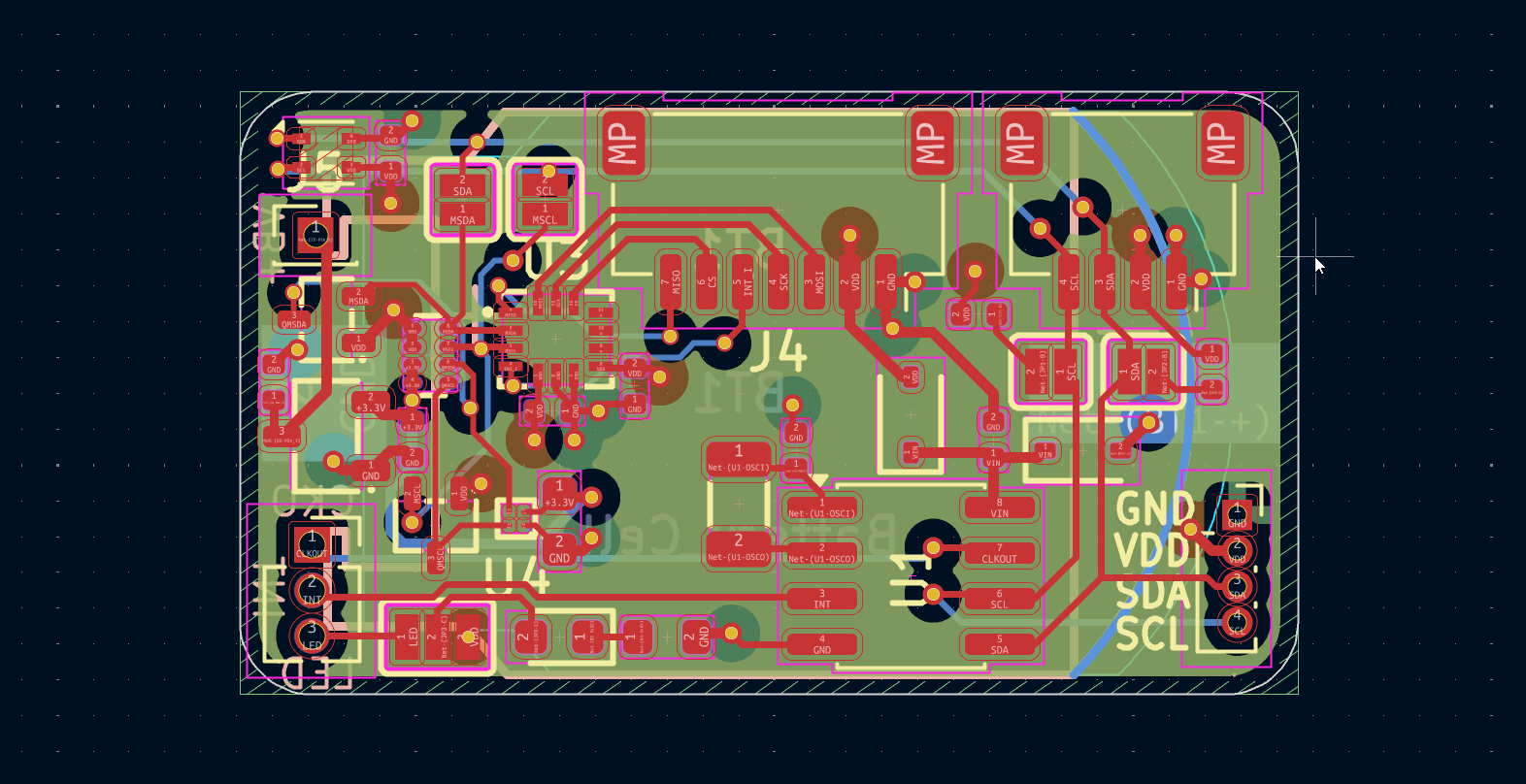
Pcf8563-breakout is an open-source printed circuit board by picafe, from the picafe/sensors-breakout repository on GitHub. It is a 4-layer board of 29.5 × 16.8 mm with 34 parts on 29 nets, routed with 252 tracks and 43 vias.
It is built around the QMC6309, PCF8563T/5 and XC6206P332MR, with the BSS138W, RB751V-40 and Q13FC1350000400 among its other parts. Its parts include 8 capacitors, 5 ICs, 5 connectors, 4 resistors and 3 diodes. It belongs with the interfaces and adapters and sensors and measurement boards of this library.


Small 4-layer KiCad PCB that packs a RTC and several I²C and SPI sensors into a compact board (around 3x1.5 cm) for cheap assembly, lots of config options, and testing sensors.
A breakout board of the PCF8563 RTC, Sensirion SHT41 temperature/humidity sensor on an I²C bus. There is a STMicro LSM6DSV IMU connected over SPI with a 7-pin JST SH connector, and QST QMC6309 magnetometer connected over I²C to the LSM6DSV's sensorhub with level shifting.
1.8 V power + logic for the RTC, temp sensor, and IMU, while keeping the magnetometer at 3.3 V via a LDO and BSS138 level shifter, so the design stays compatible with economic JLC PCBA (since QMC6309 is the only precise magnetometer offered with economic PCBA).
The board started as a quick PCF8563 test board which would go on a few of my other projects, and now is a general purpose board for testing sensors, with QWIIC-style connectors (JST SH).
| Area | Detail |
|---|---|
| RTC | PCF8563 + crystal |
| Temp/Humidity | SHT41 (can be populated from a cheap breakout or omitted) |
| Motion | LSM6DSV 6-axis IMU |
| Magnetometer | QMC6309 |
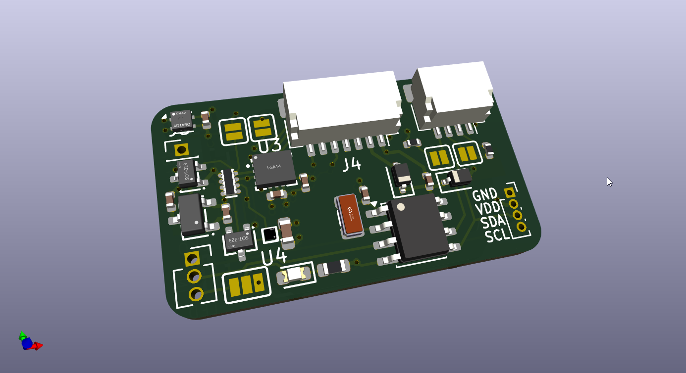
3D view:
| Qty | Value | Footprint | References |
|---|---|---|---|
| 4 | 100nF | PCM_JLCPCB:C_0402 | C1, C3, C4, C5 |
| 4 | SolderJumper_2_Open | Jumper_Sparkfun:SolderJumper-2-Sparkfun | JP1, JP2, JP4, JP5 |
| 2 | 10kΩ | PCM_JLCPCB:R_0402 | R1, R2 |
| 2 | 1uF | PCM_JLCPCB:C_0402 | C7, C8 |
| 2 | BSS138W | PCM_JLCPCB:Q_SOT-323 | Q1, Q2 |
| 2 | RB751V-40 | PCM_JLCPCB:D_SOD-323 | D1, D2 |
| 1 | 10kΩ | PCM_JLCPCB:R_0402x4 | R4 |
| 1 | 1kΩ | PCM_JLCPCB:R_0603 | R3 |
| 1 | 2.2uF | PCM_JLCPCB:C_0603 | C6 |
| 1 | 22pF | PCM_JLCPCB:C_0402 | C2 |
| 1 | Battery_Cell | easyeda2kicad:BAT-SMD_BS-CR2032-8 | BT1 |
| 1 | Conn_01x01_Pin | Connector_PinHeader_1.27mm:PinHeader_1x01_P1.27mm_Vertical | J5 |
| 1 | Conn_01x03_Pin | Connector_PinSocket_1.27mm:PinSocket_1x03_P1.27mm_Vertical | J2 |
| 1 | Conn_01x04_Socket | Connector_PinSocket_1.00mm:PinSocket_1x04_P1.00mm_Vertical | J3 |
| 1 | Conn_01x04_Socket | Connector_JST:JST_SH_SM04B-SRSS-TB_1x04-1MP_P1.00mm_Horizontal | J1 |
| 1 | Conn_01x07_Socket | Connector_JST:JST_SH_SM07B-SRSS-TB_1x07-1MP_P1.00mm_Horizontal | J4 |
| 1 | LSM6DSVQTR | easyeda2kicad:LGA-14_L3.0-W2.5-P0.50-TL | U3 |
| 1 | PCF8563T | Package_SO:SOIC-8_3.9x4.9mm_P1.27mm | U1 |
| 1 | Q13FC1350000400 | PCM_JLCPCB:FC-135R_L3.2-W1.5 | X1 |
| 1 | QMC6309 | easyeda2kicad:X1-WLB0808-4_L0.8-W0.8-P0.40-TL | U4 |
| 1 | Red | PCM_JLCPCB:D_0603 | D3 |
| 1 | SHT4x | Sensor_Humidity:Sensirion_DFN-4_1.5x1.5mm_P0.8mm_SHT4x_NoCentralPad | U2 |
| 1 | SolderJumper_3_Open | Jumper_Sparkfun:SolderJumper-3-Sparkfun | JP3 |
| 1 | XC6206P332MR | PCM_JLCPCB:SOT-23-3_L2.9-W1.6-P1.90-LS2.8-BR | U5 |

kim-xps12/m5stack_board_unitree_brushless_digital_servo
Unitree Servo UART Board for M5Stack: auto-direction 4 Mbps half-duplex TTL bus for Unitree J288 / S288 brushless digital servos (KiCad 9, JLCPCB PCBA)

picafe/pendant
A pendant built from two PCBs: a 8×8 bicolor LED matrix module (red, orange, green) and controller board with battery charging, USB-C power, 5 V boost, and motion sensing.


Appiko/sense_snap_hw
This repository contains all the KiCad based PCB design and related documentation for all the PCBs developed at Appiko.

Glebka/FancyLight
FancyLight - an LED lamp powered by a Li-Ion battery, which can be found in used electronic cigarettes. It charges via a micro USB connector and is turned on and off using a touch button.

It measures 29.5 × 16.8 mm and has 4 copper layers, 1.6 mm thick.
34 parts, built around the QMC6309, PCF8563T/5, XC6206P332MR and BSS138W. The full list of its parts is on this page, with links to each part's symbol and footprint where PCBKit's library has them.
From the picafe/sensors-breakout repository on GitHub, at the commit this page was made from: the board is pcf8563-breakout.kicad_pcb and its schematic pcf8563-breakout.kicad_sch. PCBKit opens the board in the browser, with nothing to install.
Its repository states no licence, so its author keeps all rights: ask picafe before reusing the design.