2 layers41.9 × 18.2 mm
Fsae pihat usbmod
picafe/fsae-daq-hat
A Raspberry Pi 4B hat to help power analytics in a FSAE car ⚡
3 parts

 picafe/fsae-daq-hat
A Raspberry Pi 4B hat to help power analytics in a FSAE car ⚡
Fsae pihat is an open-source printed circuit board by picafe, from the picafe/fsae-daq-hat repository on GitHub. It is a 4-layer board of 85 × 56 mm with 73 parts on 104 nets, routed with 479 tracks and 185 vias.
It is built around the SN65HVD230DR-JSM, TPS5430DDAR and PCF8563T/5, with the TPS1H200AQDGNRQ1, SS54 and RB751V-40 among its other parts. Its parts include 21 resistors, 12 capacitors, 12 diodes, 5 ICs and 5 connectors.


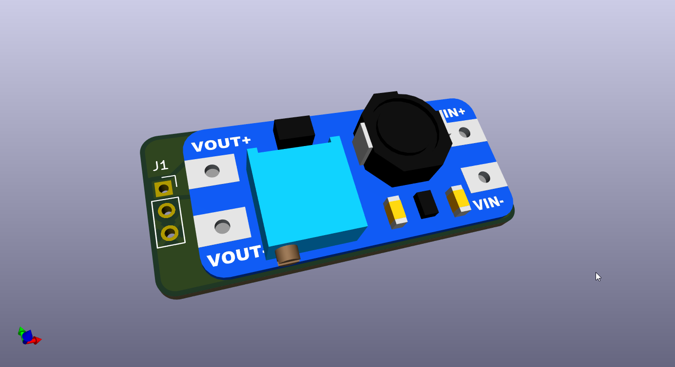
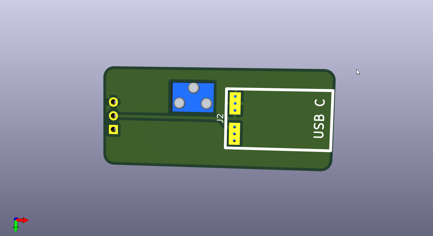
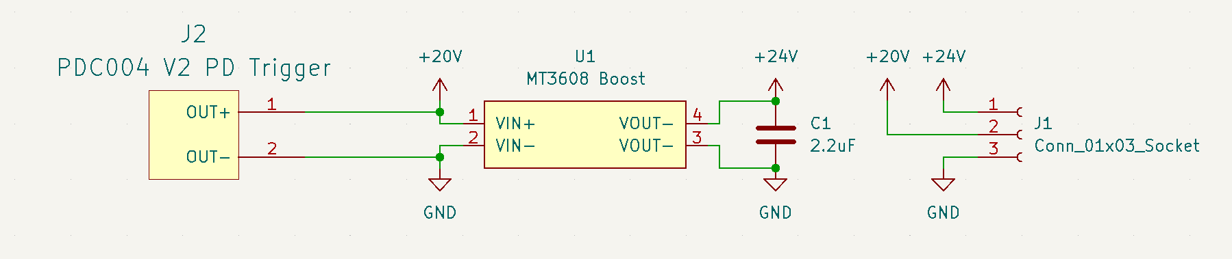
This PCB is the external 20 V USB-C PD → 24 V boost module used with the main Pi HAT. It pairs a PDC004 V2 USB-C PD trigger (fixed 20 V) with an MT3608 boost module to generate 24 V for PoE injection on the base station antenna and for convenient bench power during testing. This is a companion PCB to the main Pi HAT.
Since the current here would be pretty low, I decided to use a MT3608 and PDC004 PD module (I already have one, and the design seems pretty good; really big power plane on bottom) on a separate PCB instead of putting a boost converter on the HAT.
The MT3608 module also should be able to handle the current required (2 A) for the 24 V PoE injection, which should be around 1 A peak. The IC itself is pretty capable; there often just is not a great component selection or insufficient decoupling/filtering. I remembered this GreatScott video where he added a 2.2 µF 1210 capacitor to the output of the MT3608 to improve output ripple, so I added C1 (2.2 µF).
View schematic online (KiCanvas)
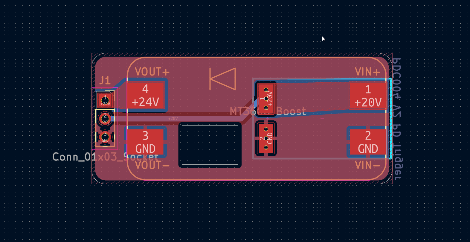
Connect to the main HAT J3 and a USB-C PD supply:
USB-C PD supply (20 V negotiated)
    │
    ▼
PDC004 module (J2, bottom of this PCB) ──► +20 V rail
    │
    ▼
MT3608 boost (U1, top of this PCB) ──► +24 V
    │
    ▼
3-pin header J1 ──► wires ──► Deutsch connectors ──► main HAT J3
For the PCB, the PD module is surface mount on the bottom and the MT3608 on the top, since both have large pads on both sides with vias.
| Designator | Footprint / package | Qty | Value | Notes |
|---|---|---|---|---|
| J1 | PinSocket_1x03_P2.54mm_Vertical | 1 | Conn_01x03_Socket | To main HAT |
| J2 | PDC004 Module | 1 | PDC004 PD Trigger | Fixed 20 V USB-C PD; AliExpress module |
| U1 | MT3608 Module | 1 | MT3608 Boost | AliExpress / generic boost module |
| C1 | C_1210 (hand solder on module) | 1 | 2.2 µF, 50V X7R 1210 CL32B225KBJNNNE | Output stability cap; solder on MT3608 output 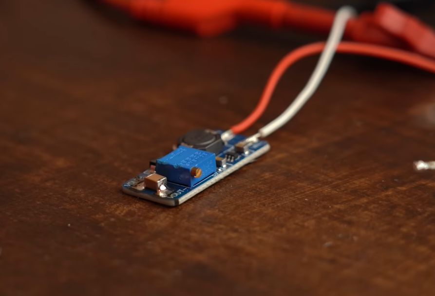 |
| Qty | Value | Footprint | References |
|---|---|---|---|
| 6 | 470Ω | PCM_JLCPCB:R_0402 | R2, R3, R7, R8, R16, R18 |
| 5 | 10kΩ | PCM_JLCPCB:R_0402 | R4, R13, R14, R19, R21 |
| 4 | SS54 | PCM_JLCPCB:D_SMA | D1, D2, D4, D5 |
| 3 | 4.7kΩ | PCM_JLCPCB:R_0402 | R10, R11, R12 |
| 3 | 4.7uF | PCM_JLCPCB:C_1206 | C1, C2, C3 |
| 3 | LOGO | LOGO | G***, G***, G*** |
| 3 | MountingHole | MountingHole:MountingHole_2.7mm_M2.5 | H2, H3, H4 |
| 2 | 1-2834011-4 | custom:CONN_1-2834011-4_TEC | J2, J3 |
| 2 | 100nF | PCM_JLCPCB:C_0603 | C11, C12 |
| 2 | 30pF | PCM_JLCPCB:C_0402 | C9, C10 |
| 2 | 3568 | easyeda2kicad:FUSE-SMD_4P-L16.0-W6.7-P3.40 | FH1, FH2 |
| 2 | Jumper_3_Open | Connector_PinHeader_2.54mm:PinHeader_1x03_P2.54mm_Vertical | JP1, JP2 |
| 2 | RB751V-40 | PCM_JLCPCB:D_SOD-323 | D7, D9 |
| 2 | TMJUTHQ0021192425 | custom:TMJUTHQ0021192425 | ETH1, ETH2 |
| 1 | 100nF | PCM_JLCPCB:C_0402 | C7 |
| 1 | 10nF | PCM_JLCPCB:C_0805 | C4 |
| 1 | 120Ω | PCM_JLCPCB:R_0603 | R17 |
| 1 | 150Ω | PCM_JLCPCB:R_0603 | R6 |
| 1 | 1812L200/30GR | easyeda2kicad:F1812 | F1 |
| 1 | 1kΩ | PCM_JLCPCB:R_0603x4 | R1 |
| 1 | 1kΩ | PCM_JLCPCB:R_0402 | R9 |
| 1 | 1kΩ | PCM_JLCPCB:R_0603 | R20 |
| 1 | 1uF | PCM_JLCPCB:C_0402 | C8 |
| 1 | 22pF | PCM_JLCPCB:C_0402 | C5 |
| 1 | 3kΩ | PCM_JLCPCB:R_0603 | R5 |
| 1 | 680Ω | PCM_JLCPCB:R_0402 | R15 |
| 1 | 6TPE330MAP | easyeda2kicad:CAP-SMD_L7.3-W4.3-R-RD | C6 |
| 1 | Battery_Cell | custom:BAT-HLD-012-SMT-TR | BT1 |
| 1 | Conn_01x03_Pin | Connector_PinSocket_2.54mm:PinSocket_1x03_P2.54mm_Vertical | J4 |
| 1 | Conn_02x02_Odd_Even | Connector_PinSocket_2.54mm:PinSocket_2x02_P2.54mm_Vertical | J5 |
| 1 | Green | PCM_JLCPCB:D_0805 | D10 |
| 1 | MCP2515-xST | Package_SO:TSSOP-20_4.4x6.5mm_P0.65mm | U5 |
| 1 | PCF8563T | Package_SO:SOIC-8_3.9x4.9mm_P1.27mm | U3 |
| 1 | Q13FC1350000400 | PCM_JLCPCB:FC-135R_L3.2-W1.5 | X1 |
| 1 | Raspberry_Pi_4 | Connector_PinSocket_2.54mm:PinSocket_2x20_P2.54mm_Vertical | J1 |
| 1 | Red | PCM_JLCPCB:D_0805 | D11 |
| 1 | SMAJ40CA | Diode_SMD:D_SMA | D6 |
| 1 | SN65HVD230DR-JSM | Package_SO:SOP-8_3.9x4.9mm_P1.27mm | U4 |
| 1 | SRR1260-150M | easyeda2kicad:IND-SMD_L12.5-W12.5_GSDRK127P | L1 |
| 1 | SS54C | easyeda2kicad:SMC_L6.9-W5.9-LS7.9-RD | D3 |
| 1 | TPS1H200AQDGNRQ1 | easyeda2kicad:EMSOP-8_L3.0-W3.0-P0.65-LS4.9-BL-EP-A | U2 |
| 1 | TPS5430DDAR | PCM_JLCPCB:ESOP-8_L4.9-W3.9-P1.27-LS6.0-TL-EP | U1 |
| 1 | TPSM24CANB-02HTG | easyeda2kicad:SOT-23-3_L2.9-W1.3-P1.90-LS2.4-BR | D8 |
| 1 | Tactile Button, 160gf | Button_Switch_SMD:SW_SPST_TS-1088-xR020 | S1 |
| 1 | X322512MSB4SI | PCM_JLCPCB:CRYSTAL-SMD_4P-L3.2-W2.5-BL | X2 |
| 1 | Yellow | PCM_JLCPCB:D_0805 | D12 |
picafe/fsae-daq-hat
A Raspberry Pi 4B hat to help power analytics in a FSAE car ⚡

picafe/sensors-breakout
Breakout board for variety of useful sensors in a tiny footprint!

btanqy/LLC-GaN-Protoboard
This board will be a prototype GaN based LLC converter, with a target rating of 80W with 24V input to 400V output, ideally for renewable power conversion and high voltage applications in plasma generation.


Appiko/sense_snap_hw
This repository contains all the KiCad based PCB design and related documentation for all the PCBs developed at Appiko.

janelia-kicad/cluster-pcb
PCB for each cluster of prisms in the Voigts Lab honeycomb maze.


It measures 85 × 56 mm and has 4 copper layers, 1.6 mm thick.
73 parts, built around the SN65HVD230DR-JSM, TPS5430DDAR, PCF8563T/5 and TPS1H200AQDGNRQ1. The full list of its parts is on this page, with links to each part's symbol and footprint where PCBKit's library has them.
From the picafe/fsae-daq-hat repository on GitHub, at the commit this page was made from: the board is fsae-pihat/fsae-pihat.kicad_pcb and its schematic fsae-pihat-usbmod/fsae-pihat-usbmod.kicad_sch. PCBKit opens the board in the browser, with nothing to install.
Its repository states no licence, so its author keeps all rights: ask picafe before reusing the design.