2 layers70.7 × 78.1 mm

 h4ctar/retro-gauge3
Open Source Motorcycle Tachometer
Pcb main is an open-source printed circuit board by h4ctar, from the h4ctar/retro-gauge repository on GitHub, published under the GPL-3.0 licence. It is a 2-layer board of 74.2 × 78.1 mm with 43 parts on 82 nets, routed with 506 tracks and 41 vias.
It is built around the ATMEGA328P-AU, PCF8563T/5 and WS2812B, with the Q13FC1350000400 and X322516MLB4SI among its other parts. Its parts include 16 diodes, 11 capacitors, 4 resistors, 4 ICs and 3 connectors. It belongs with the AVR (ATmega, ATtiny) boards of this library.


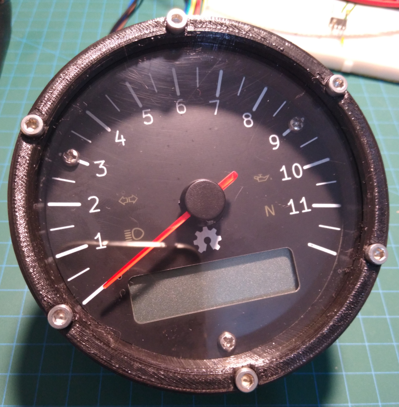
This is an open source motorcycle tacho project with the following features:
It is housed in a classic round casing, with a retro looking 8 digit starburst LCD.
The toolchain is all open source; the PCB's are designed with KiCad and the case is designed in FreeCAD.
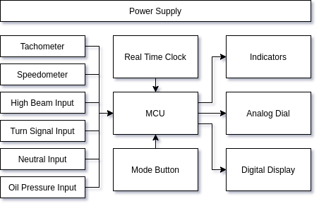
The system design is simple, the only interesting decision is that the indicators all go via the microcontroller, this lets us do fun things with the indicators (test them when powered on or reuse the oil pressure indicator for other warnings).
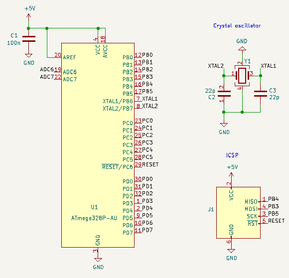
An ATmega328P-PU microcontroller will be used to process all the inputs, and drive the outputs.
Here are all the required inputs and outputs:
| Function | Type | Number of pins |
|---|---|---|
| Tacho | Digital input | 1 |
| Speedo | Digital input | 1 |
| Oil pressure | Digital input | 1 |
| Turn signals | Digital input | 1 |
| Neutral | Digital input | 1 |
| High beam | Digital input | 1 |
| Mode button | Digital input | 1 |
| Battery voltage | Analog input | 1 |
| Stepper motor | Digital output | 4 (could be 3) |
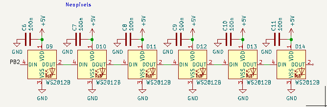
| RBG LEDs | Digital output | 1 |
| LCD | Digital output | 3 |
| ISP | Digital IO | 3 (can be shared) |
| Real time clock | Digital IO | 2 |
For a total of 18 digital IOs and one analog input, the ATmega328P-PU has more than enough at 23 programmable IO lines.
The ATmega328P-PU also has 1024 bytes of EEPROM which can be used to store the configuration, trip and odometer values.
An external 16 MHz crystal will be used to run the ATmega328P-PU at it's fastest clock speed.
The microcontroller will be programmed with an in-circuit serial programmer (ICSP). A bootloader doesnt need to be burned when using ICSP.
The low byte fuses configure the clock:
| Bit | Name | Description | Value |
|---|---|---|---|
| 7 | CKDIV8 | When set, divides the clock speed by 8 | 1 |
| 6 | CKOUT | When set, the clock pulse is output on PB0 | 1 |
| 5 | SUT1 | Sets start up delay time | 1 |
| 4 | SUT0 | 1 | |
| 3 | CKSEL3 | Sets the clock source | 1 |
| 2 | CKSEL2 | 1 | |
| 1 | CKSEL1 | 1 | |
| 0 | CKSEL0 | 1 |
The high byte fuses:
| Bit | Name | Description | Value |
|---|---|---|---|
| 7 | RSTDISBL | External reset disable | 1 |
| 6 | DWEN | Debug wire enable | 1 |
| 5 | SPIEN | Enable serial programming | 0 |
| 4 | WDTON | Watchdog timer always on | 1 |
| 3 | EESAVE | Preserve EEPROM memory through chip erase | 0 |
| 2 | EBOOTSZ1 | Sets the bootloder size memory | 1 |
| 1 | EBOOTSZ0 | 1 | |
| 0 | BOOTRST | Select the reset vector | 0 |
The extended fuses:
| Bit | Name | Description | Value |
|---|---|---|---|
| 7 | Not used | 1 | |
| 6 | 1 | ||
| 5 | 1 | ||
| 4 | 1 | ||
| 3 | 1 | ||
| 2 | BODLEVEL2 | Sets the brown-out detector level | 1 |
| 1 | BODLEVEL1 | 0 | |
| 0 | BODLEVEL0 | 1 |
There is a simple Makefile that compiles and links the code and has targets to burn the fuses and the code.
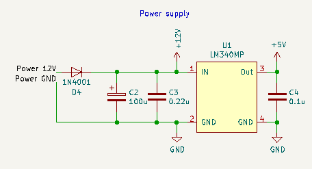
A linear voltage regulator will be used to convert the bikes rough 14V down to a smooth 5V for the rest of the system. A smoothing capacitor is added on the bikes side to help smooth out the input before it gets to the regulator.
There are indicator lights for low oil pressure, neutral, high beam and turn signals.
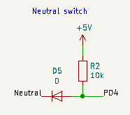
The oil pressure and neutral sensors are simple switches to ground. So these will be directly connected to digital input pins. I'm not sure if the internal pull ups will be good enough so there will be provision on the PCB for external pull up resistors. There will be a diode to protect against connecting this pin to 12V on the bike.
The highbeam and turn signals indicators should light up when they see 12V. We'll use an optocoupler to give some extra protection. The left and right turn signals need to go through diodes to stop them turning each other on.
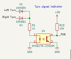
Diode forward voltage: 0.715V
Photodiode forward voltage: 1.3V
Photodiode forward current: 10mA
R1 = (14V - 0.715V - 1.3V) / 10mA = 1200 ohm ~= 1k ohmCTR: 50%
Output current: 50% of 10mA = 5mA
Output voltage: 4V
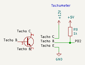
R2 = (5V - 4V) / 5mA = 200 ohmThere are a few choices for the tachometer pickup, an inductive or capacitive pickup on one of the spark plug wires, or a hall effect sensor on a rotating part of the engine. The most robust solution is to go with the hall effect sensor, and the most universal location for it is in replacement of the mechanical drive off the camshaft of the original tachometer.
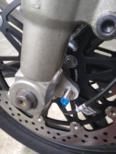
The speedometer will also be a hall effect pickup, but will be a simpler design with a few magnets on the wheel and an NPN hall effect sensor mounted on an axel spacer.
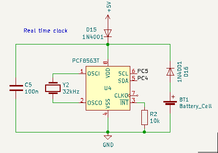
A PCF8563T RTC module will be used to keep the time for the clock. It will have a coin cell to keep the clock ticking when the key is off.
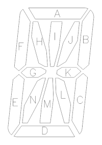
The VIM-878-DP-FC-S-LV LCD display will be used. It is a transflective LCD so works well in both bright sunlight and at night with a backlight. It is an 8 character 14 (plus 2) segment "starburst" display. It has a total of (14 + 2) * 8 = 128 segments and uses 4 backplanes.
The HT1621B will be used to drive the LCD. There are some existing Arduino libraries to interface with it. It can drive 32 segments by 4 commons which is exactly what is required to drive the selected LCD.
The schematic of the driver to the display follows the application notes in the datasheet and is optimised for the PCB layout. It is controlled with 3 pins that are also used by the ICSP.
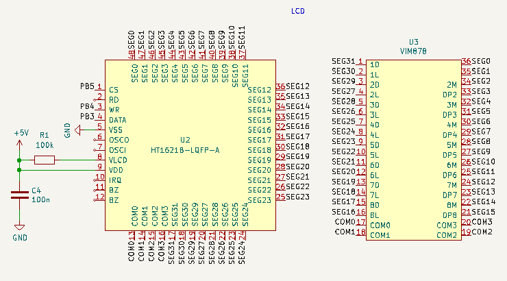
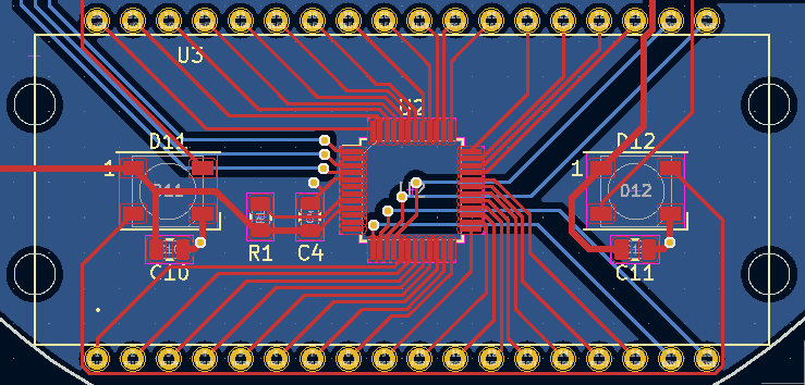
This table has the LCD segments from the datasheet and what memory address they are according to the PCB layout:
| LCD Pin | COM0 | COM1 | COM2 | COM3 | Memory address |
|---|---|---|---|---|---|
| 1 | 1D | 1E | 1F | CA1 | 31 |
| 2 | 1L | 1K | 1J | 1I | 30 |
| 3 | 2D | 2E | 2F | CA2 | 29 |
| 4 | 2L | 2K | 2J | 2I | 27 |
| 5 | 3D | 3E | 3F | CA3 | 28 |
| 6 | 3L | 3K | 3J | 3I | 26 |
| 7 | 4D | 4E | 4F | CA4 | 25 |
| 8 | 4L | 4K | 4J | 4I | 24 |
| 9 | 5D | 5E | 5F | CA5 | 23 |
| 10 | 5L | 5K | 5J | 5I | 22 |
| 11 | 6D | 6E | 6F | CA6 | 21 |
| 12 | 6L | 6K | 6J | 6I | 20 |
| 13 | 7D | 7E | 7F | CA7 | 19 |
| 14 | 7L | 7K | 7J | 7I | 18 |
| 15 | 8D | 8E | 8F | CA8 | 17 |
| 16 | 8L | 8K | 8J | 8I | 16 |
| 17 | COM0 | ||||
| 18 | COM1 | ||||
| 19 | COM2 | ||||
| 20 | COM3 | ||||
| 21 | DP8 | 8C | 8B | 8A | 15 |
| 22 | 8M | 8N | 8G | 8H | 14 |
| 23 | DP7 | 7C | 7B | 7A | 13 |
| 24 | 7M | 7N | 7G | 7H | 12 |
| 25 | DP6 | 6C | 6B | 6A | 11 |
| 26 | 6M | 6N | 6G | 6H | 10 |
| 27 | DP5 | 5C | 5B | 5A | 9 |
| 28 | 5M | 5N | 5G | 5H | 8 |
| 29 | DP4 | 4C | 4B | 4A | 7 |
| 30 | 4M | 4N | 4G | 4H | 6 |
| 31 | DP3 | 3C | 3B | 3A | 5 |
| 32 | 3M | 3N | 3G | 3H | 4 |
| 33 | DP2 | 2C | 2B | 2A | 3 |
| 34 | 2M | 2N | 2G | 2H | 2 |
| 35 | DP1 | 1C | 1B | 1A | 1 |
| 36 | 1M | 1N | 1G | 1H | 0 |
From this table we can see that each digit is powered by 4 LCD pins that map to 4 memory addresses. For example digit 1 is LCD pins 35, 1, 2 and 36, which map to memory address' 1, 31, 30 and 0.
The font maps ASCII characters to the segments in order CA,F,E,D,I,J,K,L,A,B,C,DP,H,G,N,M. The segments are in this order so the nibbles match the memory layout of the driver.
The address mapping maps digits to the 4 memory addresses that the font nibbles should be written to.
| Digit | Address' |
|---|---|
| 1 | 1,31,30, 0 |
| 2 | 3,29,27, 2 |
| 3 | 5,28,26, 4 |
| 4 | 7,25,24, 6 |
| 5 | 9,23,22, 8 |
| 6 | 11,21,20,10 |
| 7 | 13,19,18,12 |
| 8 | 15,17,16,14 |
This font table and address mapping should be enough to display text on the LCD.
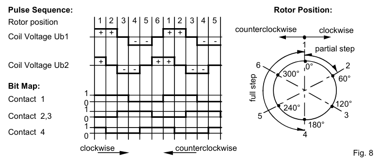
The X27.168 stepper motor will be used, it is designed for gauges and can be directly driven from a microcontroller.
People on the internet say that clamping diodes are required, so they will be added.
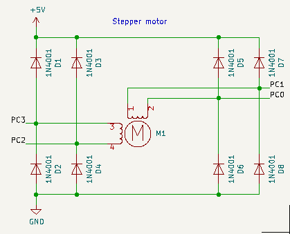
The X25 datasheet shows the required pattern to step the motor.
There are three PCBs: the main board, the sensor board and the face board. The boards are stacked using standoffs and are connected together with 2.54mm stacking header pins.
The main board has the microcontroller, stepper motor, LCD, real time clock and indicators. The sensor board has the power supply and the signal conditioning. The face board is the dial face and has transparent icons for the indicators.
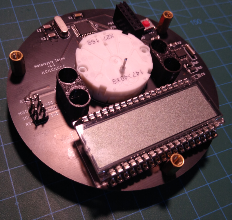
The case is 3D printed out of ASA.
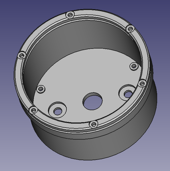
The ODO, trip and configuration will be stored in EEPROM.
EEPROM has like 100,000 writes before it wears out, so in order to be able to store the ODO and trip we will need to be able to rotate to new address'. To do this we will have a table at the start of the EEPROM that stores the address of each value and if the EEPROM gets corrupt we will find a new place to store it and update the table.
| Address | Size | Description |
|---|---|---|
| 0 | 8 | ODO Address |
| 1 | 8 | Trip Address |
| 2 | 8 | Wheel diameter |
| 15 | 8 | Next available address |
| 16 | 32 | ODO value |
| 20 | 32 | Trip value |
The source code is in the firmware/src directory.
There is a makefile with a default target to compile and link the source into a hex file; a burn target to burn this hex to the micro and a fuses target to write the fuses.
It is configured to use avrdude and a usbtiny programmer to talk to the microcontroller, but it should be possible to modify it to use other methods.
The code is compiled with clang.
There is a compile_flags.txt file that is used to configure a language server so that Vim or Visual Studio Code can give nice completion and code navigation.
On Arch linux I install the following tools and dependencies:
| Qty | Value | Footprint | References |
|---|---|---|---|
| 9 | 100n | Capacitor_SMD:C_0805_2012Metric | C1, C4, C5, C6, C7, C8, C9, C10, C11 |
| 8 | 1N4001 | Diode_SMD:D_1206_3216Metric_Pad1.42x1.75mm_HandSolder | D1, D2, D3, D4, D5, D6, D7, D8 |
| 6 | WS2812B | LED_SMD:LED_WS2812B_PLCC4_5.0x5.0mm_P3.2mm | D9, D10, D11, D12, D13, D14 |
| 3 | 10k | Resistor_SMD:R_0805_2012Metric | R2, R3, R7 |
| 2 | 1N4001 | Diode_SMD:D_SOD-323 | D15, D16 |
| 2 | 22p | Capacitor_SMD:C_0805_2012Metric | C2, C3 |
| 1 | 100k | Resistor_SMD:R_0805_2012Metric | R1 |
| 1 | ATmega328P-AU | Package_QFP:TQFP-32_7x7mm_P0.8mm | U1 |
| 1 | AVR-ISP-6 | Connector_PinHeader_2.54mm:PinHeader_2x03_P2.54mm_Vertical | J1 |
| 1 | Battery_Cell | footprints:CR1220 | BT1 |
| 1 | Conn_01x02_Male | Connector_JST:JST_PH_S2B-PH-K_1x02_P2.00mm_Horizontal | J3 |
| 1 | Conn_02x06_Counter_Clockwise | Connector_PinHeader_2.00mm:PinHeader_2x06_P2.00mm_Vertical | J2 |
| 1 | HT1621B-LQFP-A | Package_QFP:LQFP-48_7x7mm_P0.5mm | U2 |
| 1 | PCF8563T | Package_SO:SOIC-8_3.9x4.9mm_P1.27mm | U4 |
| 1 | Q13FC1350000400 | Crystal:Crystal_SMD_3215-2Pin_3.2x1.5mm | Y2 |
| 1 | SW_Push | Button_Switch_SMD:SW_SPST_TL3342 | SW1 |
| 1 | Stepper_Motor | footprints:X27.168 | M1 |
| 1 | VIM878 | footprints:VIM878 | U3 |
| 1 | X322516MLB4SI | Crystal:Crystal_SMD_3225-4Pin_3.2x2.5mm | Y1 |


picafe/sensors-breakout
Breakout board for variety of useful sensors in a tiny footprint!

Appiko/sense_snap_hw
This repository contains all the KiCad based PCB design and related documentation for all the PCBs developed at Appiko.


Yorha-7/Rocket
in this repo we are simulating rocket basic physics and make a onboard flight computer which utilizes MCU, gyro, pressure sensor, fin servo controls, to get realtime target tracking abilities to a solid fuel rocket.

muccc/WomoLIN
Open Source Steuerung von LIN Bus Geräten im Caravan Bereich.


It measures 74.2 × 78.1 mm and has 2 copper layers, 1.6 mm thick.
43 parts, built around the ATMEGA328P-AU, PCF8563T/5, WS2812B and Q13FC1350000400. The full list of its parts is on this page, with links to each part's symbol and footprint where PCBKit's library has them.
From the h4ctar/retro-gauge repository on GitHub, at the commit this page was made from: the board is pcb-main/pcb-main.kicad_pcb and its schematic pcb-main/pcb-main.kicad_sch. PCBKit opens the board in the browser, with nothing to install.
Its repository publishes it under the GPL-3.0 licence: you may reuse it on that licence's terms (keep the author's notice, and for a copyleft licence share your changes alike).