
4 layers100 × 50 mm
ESP32C6 Board
phancak/ESP32C6_Board
A versatile ESP32-C6 expansion board featuring Wi-Fi 6 and Bluetooth 5, designed for modular integration in proof-of-concept embedded projects.
76 partsMIT

 phancak/STM32H7_Board3
High-Performance STM32H7S3 System-on-Module | 600MHz ARM Cortex-M7 | External SDRAM & NAND Flash Integration | 4-Layer High-Speed PCB optimized for real-time control and LCD UI.
STM32H7 Board is an open-source printed circuit board by phancak, from the phancak/STM32H7_Board repository on GitHub, published under the MIT licence. It is a 4-layer board of 100 × 50 mm with 112 parts on 252 nets, routed with 3,505 tracks and 716 vias.
It is built around the SN74LVC1G07DBVR, USBLC6-2SC6 and SMAJ6.0A. Its parts include 47 capacitors, 18 resistors, 5 ICs, 4 connectors and 2 diodes. It belongs with the STM32 boards of this library.


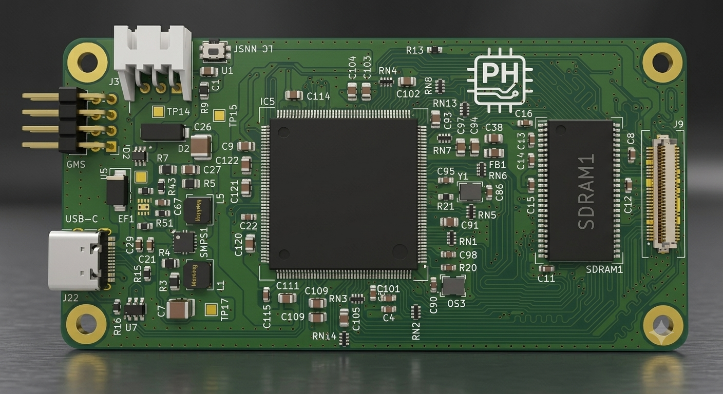


This project features a professional-grade, high-speed embedded system centered around the STM32H7S3I8T6 (ARM Cortex-M7 running at 600 MHz). Developed as a post-graduate technical showcase, this board demonstrates proficiency in high-speed digital design, complex memory interfacing (SDRAM/NAND), and modular system architecture.
The platform is designed to serve as a high-bandwidth "Main Compute Module" that interfaces with expansion boards via a variety of industrial-standard protocols (PSSI, I2S, I2C, SPI, UART).
To ensure the reliability of a 600 MHz system, the following hardware validation protocols were implemented:
Using a high-bandwidth digital oscilloscope (2 GHz+), the following critical signals are probed to verify timing margins and signal quality:
/Hardware: Schematic (PDF/Source), PCB Layout, and Layer Stackup definitions./Firmware: BSP (Board Support Package), memory initialization code, and driver implementations./Docs: Power budget analysis and timing margin calculations.I am a recent Electrical Engineering graduate from the University of British Columbia (UBC). This project represents my ability to transition theoretical academic knowledge into a complex, manufacturable high-speed digital system.
| Qty | Value | Footprint | References |
|---|---|---|---|
| 18 | 100n | Capacitor_SMD:C_0603_1608Metric | C4, C5, C6, C8, C11, C12, C13, C14, C15, C16, C17, C19, C46, C49, C101, C115 +2 |
| 14 | 33R | Resistor_SMD:R_Array_Convex_4x0402 | RN1, RN2, RN3, RN4, RN5, RN6, RN7, RN8, RN9, RN10, RN11, RN13, RN14, RN16 |
| 13 | 100n | Capacitor_SMD:C_0805_2012Metric | C35, C91, C93, C97, C102, C103, C105, C108, C109, C114, C120, C121, C122 |
| 4 | MountingHole_Pad | MountingHole:MountingHole_3.2mm_M3_Pad | H1, H2, H3, H4 |
| 4 | TestPoint | TestPoint:TestPoint_Pad_1.5x1.5mm | TP13, TP14, TP15, TP17 |
| 3 | 180k | Resistor_SMD:R_0805_2012Metric | R3, R4, R7 |
| 3 | 4u7 | Capacitor_SMD:C_0805_2012Metric | C9, C88, C104 |
| 2 | 10k | Resistor_SMD:R_0603_1608Metric | R17, R18 |
| 2 | 10n | Capacitor_SMD:C_0603_1608Metric | C86, C90 |
| 2 | 10u | Capacitor_SMD:C_0603_1608Metric | C21, C29 |
| 2 | 1M | Resistor_SMD:R_0603_1608Metric | R38, R52 |
| 2 | 1u | Capacitor_SMD:C_0805_2012Metric | C94, C111 |
| 2 | 22R | Resistor_SMD:R_0603_1608Metric | R19, R22 |
| 2 | 22u | Capacitor_SMD:C_1210_3225Metric | C7, C26 |
| 2 | 4u7 | Capacitor_SMD:C_0603_1608Metric | C22, C57 |
| 2 | 5k1 | Resistor_SMD:R_0603_1608Metric | R15, R16 |
| 2 | BTB_10132798-062100LF | Personal_Project:BTB_AMPHENOL_10132798-062100LF | J1, J9 |
| 2 | LOGO | Personal_Project:PCB_Logo | G***, G*** |
| 1 | 10k | Resistor_SMD:R_0805_2012Metric_1 | R9 |
| 1 | 1uF | Capacitor_SMD:C_0805_2012Metric | C1 |
| 1 | 22R | Capacitor_SMD:C_0603_1608Metric | R20 |
| 1 | 2u2 NR4020S2R2MT | Personal_Project:L_NR4020S2R2MT | L1 |
| 1 | 33p | Capacitor_SMD:C_0805_2012Metric | C27 |
| 1 | 383k | Resistor_SMD:R_0603_1608Metric | R43 |
| 1 | 3n3 | Capacitor_SMD:C_0603_1608Metric | C67 |
| 1 | 3u3 CPN4020H3R3MT | Personal_Project:L_NR4020S2R2MT | L5 |
| 1 | 487R | Resistor_SMD:R_0603_1608Metric | R51 |
| 1 | 4k7 | Resistor_SMD:R_0603_1608Metric | R13 |
| 1 | 51R | Resistor_SMD:R_0603_1608Metric | R21 |
| 1 | 806k | Resistor_SMD:R_0805_2012Metric | R5 |
| 1 | BLM21PG601SN1D_0805 | Capacitor_SMD:C_0805_2012Metric_Pad1.18x1.45mm_HandSolder | FB1 |
| 1 | Clock_Gen_SI5351A-B-GT | Personal_Project:Clock_Gen_SI5351 | CG1 |
| 1 | ECS-3225SMVQ-240-DS-TR | Personal_Project:Oscillator_ASE50000MHZLRT | Y1 |
| 1 | EFUSE_TPS259531DSGR | Personal_Projects:EF_TPS259531DSGR | EF1 |
| 1 | ID_LM66100DCKR | Personal_Projects:ID_LM66100DCKR | ID2 |
| 1 | JST_S3B-XH-2.54 | Personal_Projects:JST_S3B-XH-SHDRRA3W64P0X250_1X3_990X1150X610P | JST2 |
| 1 | NAND_MX30LF1G18AC-TI | Personal_Project:NAND_MT29F1G08ABAEAWP-IT_E_TR_SOP50P2000X120-48N | IC1 |
| 1 | Oscillator_ECS-327MVATX-3-CN-TR | Personal_Project:Oscillator_ECS327MVATX3CNTR | OS3 |
| 1 | SDRAM_AS4C32M8SA-7TCN | Personal_Project:SDRAM_IS42S16320F-6TL | SDRAM1 |
| 1 | SMAJ6.0A | Personal_Projects:DO-214AC-2 | D2 |
| 1 | SMPS_TPS62420DRCTG4 | Package_SON:VSON-10-1EP_3x3mm_P0.5mm_EP1.65x2.4mm | SMPS1 |
| 1 | SN74LVC1G07DBVR | Package_TO_SOT_SMD:SOT-23-5 | U4 |
| 1 | SS34-E3/57T | Diode_SMD:D_SMA | D5 |
| 1 | STM32H7S3I8T6 LQFP 176 | Personal_Project:QFP50P2600X2600X160-176N | IC5 |
| 1 | SWDB | Connector_PinHeader_2.54mm:PinHeader_2x04_P2.54mm_Horizontal | J3 |
| 1 | TSX-3225 26.0000MF09Z-AC0 | Personal_Project:Oscillator_ECS327MVATX3CNTR | Y2 |
| 1 | USBLC6-2SC6 | Package_TO_SOT_SMD:SOT-23-6 | U7 |
| 1 | USB_C_Receptacle_USB2.0_16P | Connector_USB:USB_C_Receptacle_HRO_TYPE-C-31-M-12 | J22 |
| 1 | ~ | Personal_Project:Button_SKSCLCE010 | U1 |
phancak/ESP32C6_Board
A versatile ESP32-C6 expansion board featuring Wi-Fi 6 and Bluetooth 5, designed for modular integration in proof-of-concept embedded projects.

phancak/ESP32P4C5_Board
This dual-MCU repository features a heterogeneous architecture pairing an ESP32-P4 application processor with an ESP32-C5 Wi-Fi 6/BLE hub.


PUT-Motorsport/PUTM_EV_AMS_MASTER
High Voltage Battery Management System

embeddedos-org/eCAD-Hardware-Products
Hardware designs + EE docs + Board datasheets of Multiple products

copperheadhq/copperhead-stm32-data-logger
Portable STM32L433 data logger, 50 × 70 mm, four layers, microSD, USB-C LiPo charging. Designed with copperhead. Never built: do not order expecting it to work.

Rustaphor/LightRelay4Camping
Analog light sensor to night power up LED garland. For Camping use.

Sid93/levram-biometric-attendance-scanner
ESP32-S3 face-recognition factory attendance terminal — firmware, KiCad PCB, OpenSCAD enclosure, BOM
It measures 100 × 50 mm and has 4 copper layers, 1.58 mm thick.
112 parts, built around the SN74LVC1G07DBVR, USBLC6-2SC6 and SMAJ6.0A. The full list of its parts is on this page, with links to each part's symbol and footprint where PCBKit's library has them.
From the phancak/STM32H7_Board repository on GitHub, at the commit this page was made from: the board is STM32H7_Board.kicad_pcb and its schematic Interface_Headers.kicad_sch. PCBKit opens the board in the browser, with nothing to install.
Its repository publishes it under the MIT licence: you may reuse it on that licence's terms (keep the author's notice, and for a copyleft licence share your changes alike).