
4 layers40 × 75 mm
CUR flight computer 25-26
CU-Rocketry/flight_computer
Competition Flight Computer Module 25-26
169 parts1

 phancak/ESP32P4C5_Board7
This dual-MCU repository features a heterogeneous architecture pairing an ESP32-P4 application processor with an ESP32-C5 Wi-Fi 6/BLE hub. Linked over a high-bandwidth 4-bit parallel SDIO interconnect, this design decouples heavy multimedia task execution from the networking stack to completely eliminate application interrupt starvation.
ESP32P4C5 Board is an open-source printed circuit board by phancak, from the phancak/ESP32P4C5_Board repository on GitHub, published under the MIT licence. It is a 4-layer board of 100 × 50 mm with 187 parts on 203 nets, routed with 2,207 tracks and 788 vias.
It is built around the ESP32-C5HR8, ESP32-P4NRW16 and BY25Q128ESSIG(T), with the SN74LVC1G07DBVR, USBLC6-2SC6 and ABM8W-48.0000MHZ-7-B1U-T3 among its other parts. Its parts include 81 capacitors, 41 resistors, 11 ICs, 6 connectors and 5 inductors. It belongs with the radio and wireless boards and the ESP32 and RISC-V boards of this library.


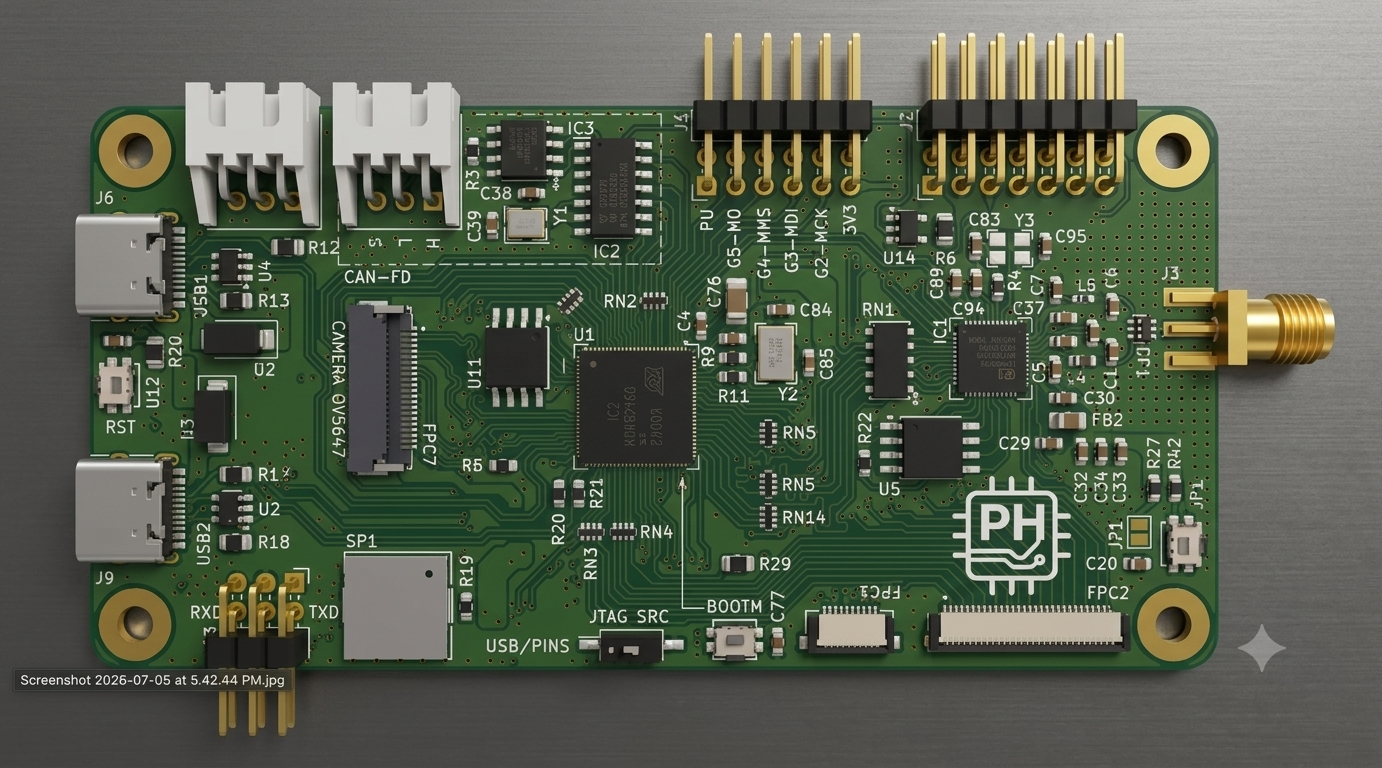


A production-grade, high-performance development platform engineered to serve as a modular, reusable core for edge computing, high-bandwidth multimedia processing, and synchronized wireless gateways.
This repository showcases an advanced asynchronous, dual-MCU topology that isolates intensive computational and real-time interface operations from wireless network stack overhead. By decoupling heavy application logic from communication tasks via a high-speed parallel bus interconnect, the architecture guarantees deterministic processing latency and maximum deployment flexibility across diverse industrial and machine vision domains.
The system architecture purposefully segregates application compute from wireless networking to maximize throughput and guarantee real-time predictability.
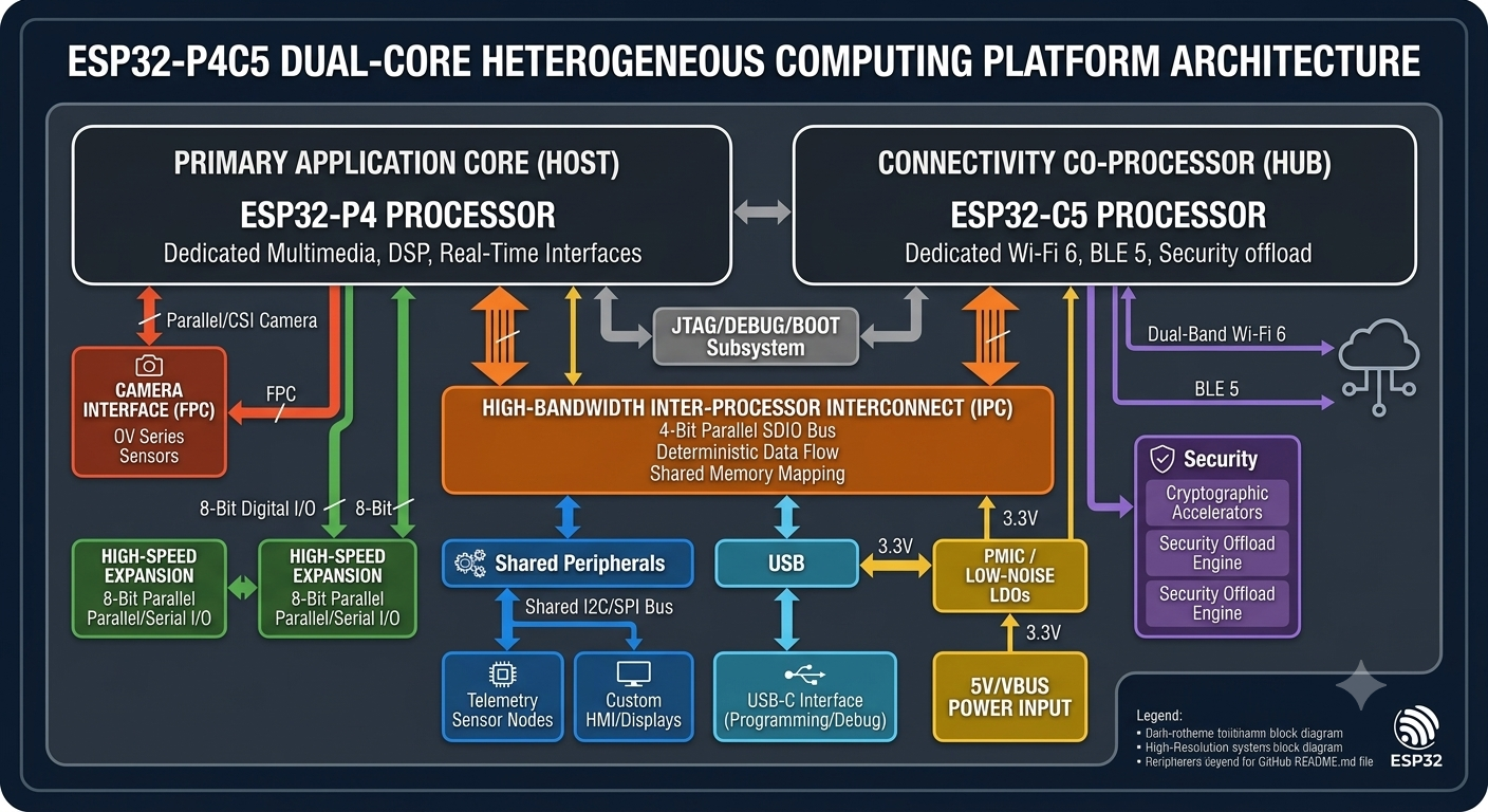
The ESP32-P4 acts as the primary host, running application firmwares, digital signal processing (DSP), and complex interface state-machines. It interfaces with high-bandwidth peripherals without experiencing interrupt starvation caused by networking radio activity.
The ESP32-C5 operates as a standalone network engine, handling the entirety of the link layer, cryptographic handshakes, and transport layer protocol stacks.
Processor synchronization is achieved over a hardware-managed 4-bit SDIO parallel interface. Unlike highly bottlenecked SPI or serial UART abstractions, this interconnect introduces wide data paths capable of handling high-rate simultaneous dual-band Wi-Fi data routing concurrently with video capture or high-speed I/O manipulation.
To fulfill its requirements as a universally integrable module, the layout strictly organizes peripheral pin assignments to mitigate trace crossover and manage signal integrity across high-speed signal groups.
| Peripheral Subsystem | Physical Interface / Interconnect | Target Engineering Application |
|---|---|---|
| Edge Vision | 0.5mm Pitch Parallel FPC | CMOS Image Sensors, Edge AI Machine Vision, Asset Monitoring |
| Parallel Bus | Low-Impedance GPIO Headers | Legacy Bus Bridging, High-Speed External Converters, Parallel LCDs |
| Synchronous Serial | Hardware SPI Bus Headers | High-Frequency IMUs, External Flash Memory, Low-Level Controllers |
| Asynchronous Serial | Dedicated Hardware UART | isolated Console Debugging, GNSS Modems, Cellular Modems |
| Control Bus | Fast-Mode Plus (Fm+) I2C | Local Telemetry Sensors, Cryptographic Co-Processors, EEPROMs, HMIs |
| System I/O & Power | Dual Independent USB-C | Native USB 2.0 Subsystems, Dedicated Programming/Debugging Bridges |
To compile and flash the primary application workspace onto the main ESP32-P4 target engine:
# Navigate to the core processor application repository
cd firmware/main_p4

# Set compilation targets explicitly to the ESP32-P4 hardware register maps
idf.py set-target esp32p4

# Execute target compilation and code optimization pass
idf.py build

# Flash binary payloads onto the hardware module and open serial communication lines
idf.py -p [YOUR_TARGET_PORT] flash monitorThis architecture and firmware codebase are released under the terms of the open-source MIT License. For complete text and details regarding reuse rights, consult the accompanying LICENSE file.
I am a recent Electrical Engineering graduate from the University of British Columbia (UBC). This project represents my ability to transition theoretical academic knowledge into a complex, manufacturable high-speed digital system.
| Qty | Value | Footprint | References |
|---|---|---|---|
| 28 | 100n | Capacitor_SMD:C_0603_1608Metric | C3, C4, C11, C17, C19, C20, C28, C29, C40, C41, C51, C53, C55, C57, C61, C64 +12 |
| 9 | 10u | Capacitor_SMD:C_1206_3216Metric | C21, C22, C24, C25, C52, C54, C60, C63, C76 |
| 8 | 10k | Resistor_SMD:R_0603_1608Metric | R1, R5, R16, R22, R23, R27, R37, R42 |
| 6 | 1u | Capacitor_SMD:C_0603_1608Metric | C49, C56, C58, C59, C89, C94 |
| 6 | TestPoint | TestPoint:TestPoint_Pad_1.5x1.5mm | TP5, TP6, TP7, TP8, TP9, TP10 |
| 5 | 10k | Resistor_SMD:R_0805_2012Metric | R6, R7, R26, R30, R31 |
| 5 | 1u | Capacitor_SMD:C_0805_2012Metric | C10, C13, C14, C66, C90 |
| 4 | 10p | Capacitor_SMD:C_0603_1608Metric | C2, C23, C84, C85 |
| 4 | 33R | Resistor_SMD:R_Array_Convex_4x0402 | RN2, RN5, RN6, RN14 |
| 4 | 5k1 | Resistor_SMD:R_0805_2012Metric | R12, R13, R17, R18 |
| 4 | MountingHole_Pad | MountingHole:MountingHole_3.2mm_M3_Pad | H1, H2, H3, H4 |
| 3 | 0R | Resistor_SMD:R_0603_1608Metric | R4, R9, R11 |
| 3 | 10n | Capacitor_SMD:C_0603_1608Metric | C12, C15, C50 |
| 3 | 10u | Capacitor_SMD:C_0603_1608Metric | C42, C43, C44 |
| 3 | 10u_GRM188Z71A106KA73 | Capacitor_SMD:C_0603_1608Metric | C33, C37, C91 |
| 3 | 33R | Resistor_SMD:R_0603_1608Metric | R14, R20, R21 |
| 3 | ~ | Personal_Project:Button_SKSCLCE010 | U9, U12, U13 |
| 2 | 100R | Resistor_SMD:R_0603_1608Metric | R41, R46 |
| 2 | 100n_GRM188R72A104KA35 | Capacitor_SMD:C_0603_1608Metric | C34, C36 |
| 2 | 10R | Resistor_SMD:R_Array_Convex_4x0402 | RN3, RN4 |
| 2 | 18p | Capacitor_SMD:C_0603_1608Metric | C38, C39 |
| 2 | 1M | Resistor_SMD:R_0603_1608Metric | R36, R39 |
| 2 | 470n_muRata DFE252012PD-R47M=P2 | Inductor_SMD:L_1008_2520Metric | L1, L2 |
| 2 | 4u7 | Capacitor_SMD:C_1206_3216Metric | C26, C27 |
| 2 | 68k | Resistor_SMD:R_0805_2012Metric | R44, R45 |
| 2 | 8p | Capacitor_SMD:C_0603_1608Metric | C83, C96 |
| 2 | JST_S3B-XH-2.54 | Personal_Project:JST_S3B-XH-SHDRRA3W64P0X250_1X3_990X1150X610P | JST1, JST2 |
| 2 | LOGO | Personal_Project:PCB_Logo | G***, G*** |
| 2 | SN74LVC1G07DBVR | Package_TO_SOT_SMD:SOT-23-5 | U14, U15 |
| 2 | SS34-E3/57T | Diode_SMD:D_SMA | D2, D3 |
| 2 | USBLC6-2SC6 | Package_TO_SOT_SMD:SOT-23-6 | U2, U4 |
| 2 | USB_C_Receptacle_USB2.0_16P | Connector_USB:USB_C_Receptacle_HRO_TYPE-C-31-M-12 | J6, J9 |
| 1 | 0p3 | Capacitor_SMD:C_0603_1608Metric | C6 |
| 1 | 0p4 | Capacitor_SMD:C_0603_1608Metric | C7 |
| 1 | 0p6 | Capacitor_SMD:C_0603_1608Metric | C5 |
| 1 | 0p6_GQM1875C2ER60BB12 | Capacitor_SMD:C_0603_1608Metric | C93 |
| 1 | 10k(1%) | Resistor_SMD:R_0805_2012Metric_1 | R29 |
| 1 | 10k(1%) | Resistor_SMD:R_0603_1608Metric | R28 |
| 1 | 10n_GRM188R72A103KA01 | Capacitor_SMD:C_0603_1608Metric | C35 |
| 1 | 10u | Capacitor_SMD:C_0805_2012Metric | C62 |
| 1 | 110k | Resistor_SMD:R_0603_1608Metric | R25 |
| 1 | 120R | Resistor_SMD:R_0603_1608Metric | R3 |
| 1 | 19k6 | Resistor_SMD:R_0805_2012Metric | R43 |
| 1 | 1n3 | Inductor_SMD:L_0402_1005Metric_Pad0.77x0.64mm_HandSolder | L5 |
| 1 | 1p | Capacitor_SMD:C_0603_1608Metric | C1 |
| 1 | 1p_GQM1875C2E1R0WB12D | Capacitor_SMD:C_0603_1608Metric | C92 |
| 1 | 220R | Resistor_SMD:R_0603_1608Metric | R19 |
| 1 | 22R | Resistor_SMD:R_Array_Convex_4x0402 | RN17 |
| 1 | 2n4 | Inductor_SMD:L_0603_1608Metric | L4 |
| 1 | 2p6 | Capacitor_SMD:C_0603_1608Metric | C30 |
| 1 | 2u2_LPS3015-222MRC | Inductor_SMD:L_Coilcraft_LPS3010 | L3 |
| 1 | 33k2 | Resistor_SMD:R_0603_1608Metric | R24 |
| 1 | 383k | Resistor_SMD:R_0603_1608Metric | R38 |
| 1 | 3n3 | Capacitor_SMD:C_0603_1608Metric | C16 |
| 1 | 3p_GQM1875C2E3R0BB12D | Capacitor_SMD:C_0603_1608Metric | C32 |
| 1 | 464k | Resistor_SMD:R_0603_1608Metric | R15 |
| 1 | 487R | Resistor_SMD:R_0603_1608Metric | R40 |
| 1 | 4k02_1% | Resistor_SMD:R_0603_1608Metric | R8 |
| 1 | 4u7 | Capacitor_SMD:C_0805_2012Metric | C73 |
| 1 | 88k7 | Resistor_SMD:R_0805_2012Metric | R10 |
| 1 | ABM8W-48.0000MHZ-7-B1U-T3 | Crystal:Crystal_SMD_Abracon_ABM8AIG-4Pin_3.2x2.5mm | Y3 |
| 1 | BLM21PG601SN1D_0805 | Capacitor_SMD:C_0805_2012Metric_Pad1.18x1.45mm_HandSolder | FB2 |
| 1 | BY25Q128ESSIG(T) | Package_SO:SOP-8_5.28x5.23mm_P1.27mm | U11 |
| 1 | CAN_ATA6563-GAQW1 | Personal_Project:CAN_ATA6563_GAQW1 | IC3 |
| 1 | Crystal_ABM8G-40.000MHZ-18-D2Y-T | Crystal:Crystal_SMD_Abracon_ABM8G-4Pin_3.2x2.5mm | Y1 |
| 1 | DIPLEXER_DPX205950DT-9026A1 | Personal_Project:DIPLEXER_DPX205950DT-9026A1 | DP1 |
| 1 | Debug_Pins | Connector_PinHeader_2.54mm:PinHeader_2x07_P2.54mm_Horizontal | J2 |
| 1 | Diode_PESD5V0U2BT-Q | Package_TO_SOT_SMD:SOT-23 | DI2 |
| 1 | ECS-400-10-33B-CKM-TR | Personal_Project:Crystal_ECS-400-10-30B-CKM-TR | Y2 |
| 1 | EFUSE_TPS259531DSGR | Personal_Project:EFUSE_TPS259531DSGR | EF1 |
| 1 | ESP32-C5HR8 | Personal_Project:QFN40P600X600X90-49N-D | IC1 |
| 1 | ESP32-P4NRW16 | Personal_Project:ESP32-P4NRW16 | U1 |
| 1 | FPC_10051922-1010ELF | Personal_Project:FPC_10051922_1010 | FPC1 |
| 1 | FPC_AMPHENOL_10051922-3010ELF | Personal_Project:FPC_AMPHENOL_10051922-3010ELF | FPC2 |
| 1 | FPC_FPC05-WFB11-22P111-H20 | Personal_Project:FPC_FPC05-WFB11-22P111-H20 | FPC7 |
| 1 | I2C1_Headers | Personal_Project:PinHeader_2x03_P2.54mm_Horizontal_Court | J13 |
| 1 | Ideal_Diode_LM73100RPWR | Personal_Project:Ideal_Diode_LM73100RPWR | ID1 |
| 1 | P4_DEBUG_PINS | Connector_PinHeader_2.54mm:PinHeader_2x06_P2.54mm_Horizontal | J1 |
| 1 | RNET_EXB-A10P473J | Personal_Project:RNET_EXB-A10P473J | RN1 |
| 1 | SMA PCB END LAUNCH JACK ROUND PO | Personal_Project:SMA Clip Mount Adapter (top) | J3 |
The 179 most common of 187 parts.
CU-Rocketry/flight_computer
Competition Flight Computer Module 25-26


phancak/STM32H7_Board
High-Performance STM32H7S3 System-on-Module | 600MHz ARM Cortex-M7 | External SDRAM & NAND Flash Integration | 4-Layer High-Speed PCB optimized for real-time control and LCD UI.


phancak/ESP32C6_Board
A versatile ESP32-C6 expansion board featuring Wi-Fi 6 and Bluetooth 5, designed for modular integration in proof-of-concept embedded projects.

PUT-Motorsport/PUTM_EV_AMS_MASTER
High Voltage Battery Management System
It measures 100 × 50 mm and has 4 copper layers, 1.58 mm thick.
187 parts, built around the ESP32-C5HR8, ESP32-P4NRW16, BY25Q128ESSIG(T) and SN74LVC1G07DBVR. The full list of its parts is on this page, with links to each part's symbol and footprint where PCBKit's library has them.
From the phancak/ESP32P4C5_Board repository on GitHub, at the commit this page was made from: the board is ESP32P4C5_Board.kicad_pcb and its schematic Buttons.kicad_sch. PCBKit opens the board in the browser, with nothing to install.
Its repository publishes it under the MIT licence: you may reuse it on that licence's terms (keep the author's notice, and for a copyleft licence share your changes alike).