Skip to the content
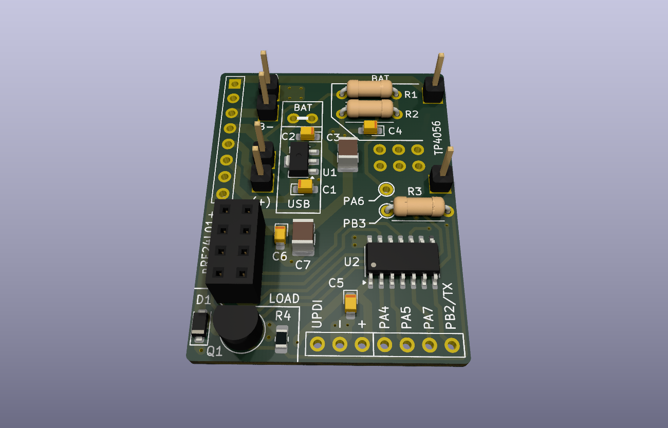
2 layers32 × 41 mmNRF node smd, the printed circuit board in 3D

Solar/Battery/USB powered wireless "smarthome" modules

Size
32 × 41 mm
Copper layers
2
Thickness
1.6 mm
Parts
24
Nets
23
Pads
84
Tracks, vias
372, 26
Pours
1
Routed
Yes
KiCad
KiCad 8.0 (file 20240108)
Created
27 Jul 2024
Updated
27 Jul 2024

Overview

NRF node smd is an open-source printed circuit board by Peppson, from the Peppson/radio-nodes repository on GitHub. It is a 2-layer board of 32 × 41 mm with 24 parts on 23 nets, routed with 372 tracks and 26 vias.

It is built around the ATTINY84A-PU. Its parts include 7 capacitors, 4 resistors, 2 ICs, 1 diode and 1 transistor. It belongs with the power and home automation and IoT boards and the AVR (ATmega, ATtiny) boards of this library.

Main components

1

README

README.md

flow_diagram

radio-nodes

Solar/Battery/USB powered wireless "smarthome" modules, based on the Attiny824 microcontroller.
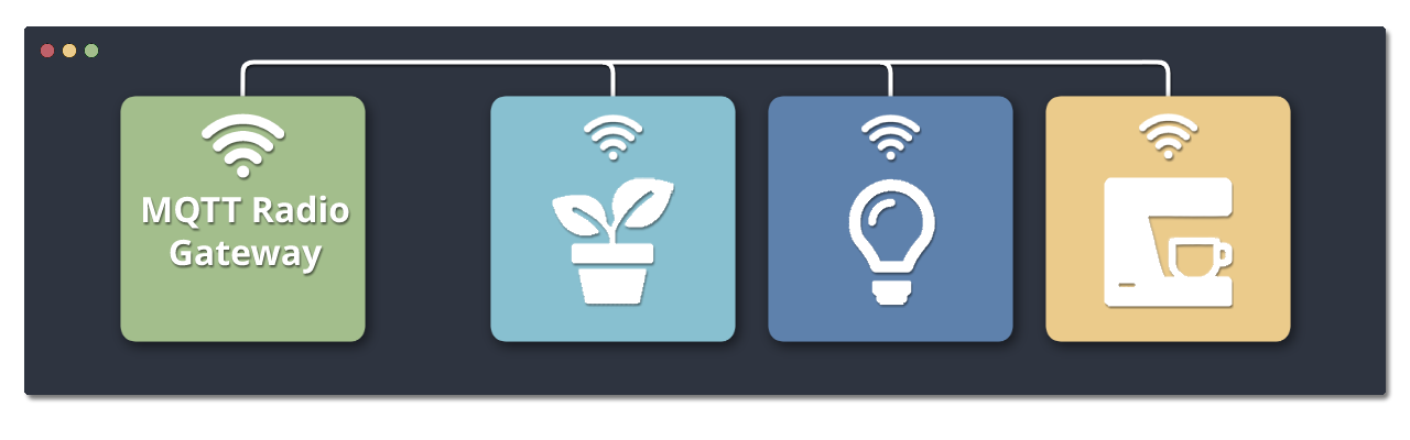
Serves as the end-node of MQTT-radio-gateway.
Written in C++ with PlatformIO.


Project Overview

  • Each node is easily configurable to perform various tasks, such as watering plants,
    turn on the coffeemaker, opening blinds, relaying sensor data, etc.

  • Power consumption was the main concern when designing this.
    Nodes consumes ∼2mA @ 3.3V in active listening mode, and as low as ∼3uA @ 3.3V while deepsleeping!
    Making it possible to power some nodes indefinitely from a small solarpanel.
    Measured and optimized using Power Profiler Kit II.

  • This project was primarily made for personal "needs". But it is open for use by anyone who finds it beneficial.
    Every node has it's own directory inside src with it's own enviroment, selected from platformio.ini.


Hardware and PCB

Made a compact PCB integrating a TP4056 Li-ion/LiPo battery charger, an nRF24L01+ radio,
and the Attiny824 AVR microcontroller.

More images in: 📂 _images/
KiCad files: 📂 _KiCad/

Schematic
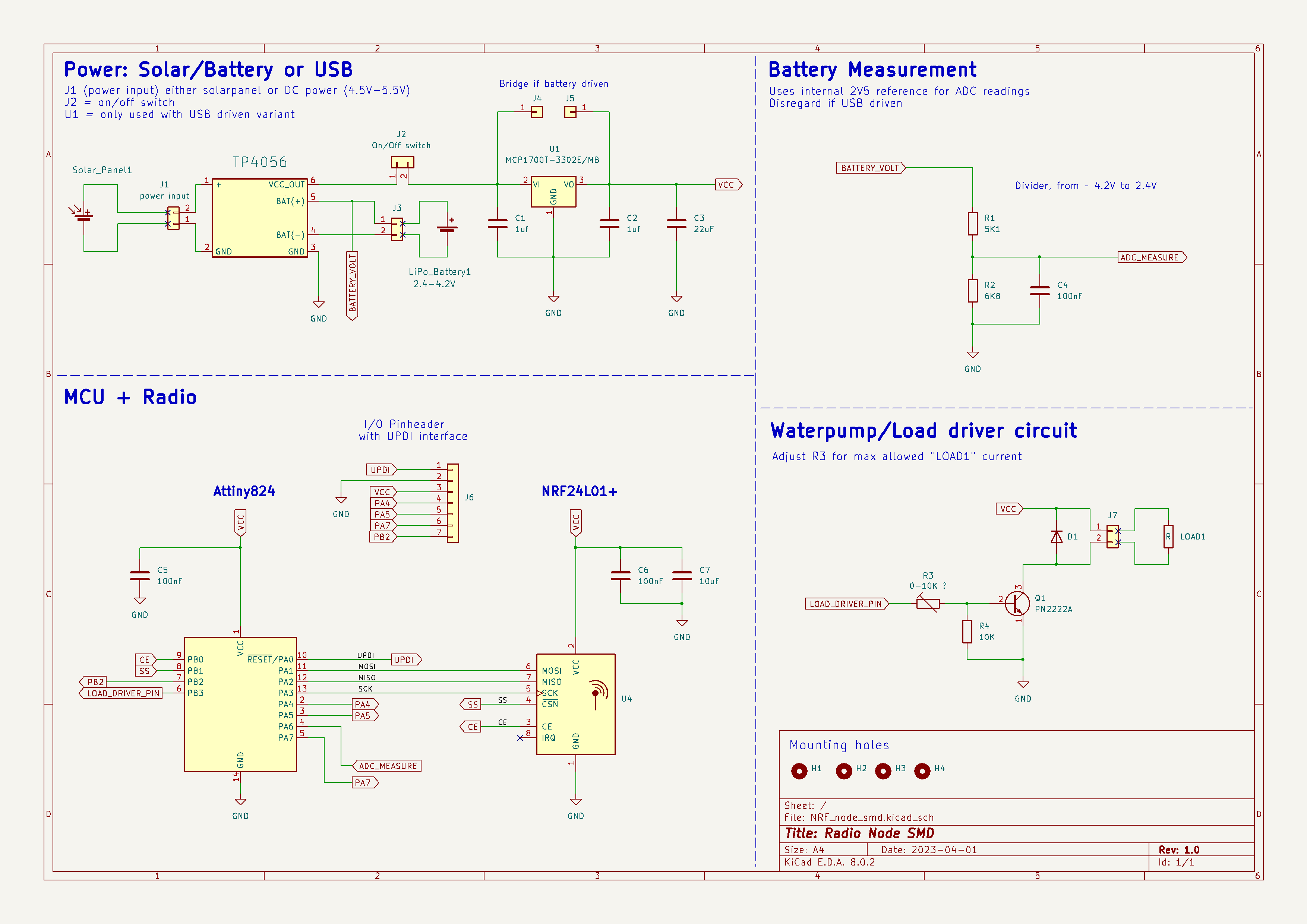
schematic

PCB layout

2-layer PCB, dimensions 42mm x 31mm.
The PCB has 3 sections, configurable based on the node.

  • BAT or USB: Battery or USB/5V driven.
  • LOAD: Components for the "load driver circuit".
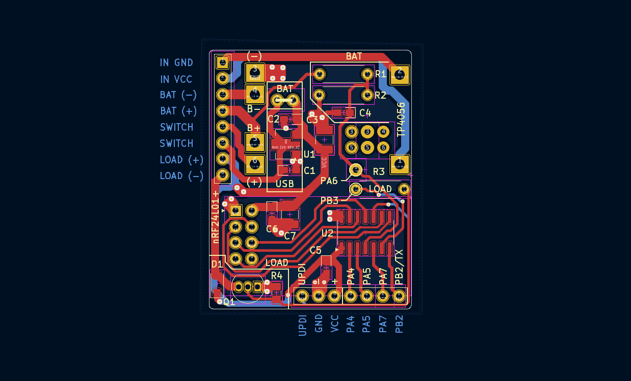
PCB_layout

Power consumption in active mode

In active mode, the node toggles its radio on for 50ms and off for 950ms to minimize power usage,
halting the CPU between pulses.

Resulting in an average power draw of ∼2mA @ 3.3V.
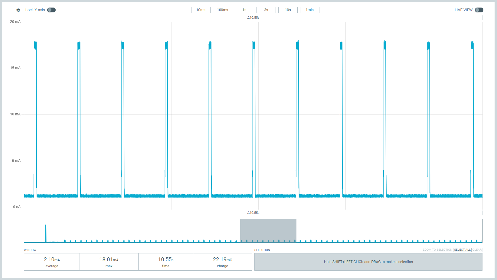
PCB_layout

Programming

The ATtiny 2-series MCUs have UPDI interface. Which makes it possible to program with only 1 data pin!
You can see the UPDI pins at the bottom of the PCB.

I created a simple DIY programmer using an Arduino Nano, to help with uploading firmware.
More details here UPDI programmer.

PCB
hardware

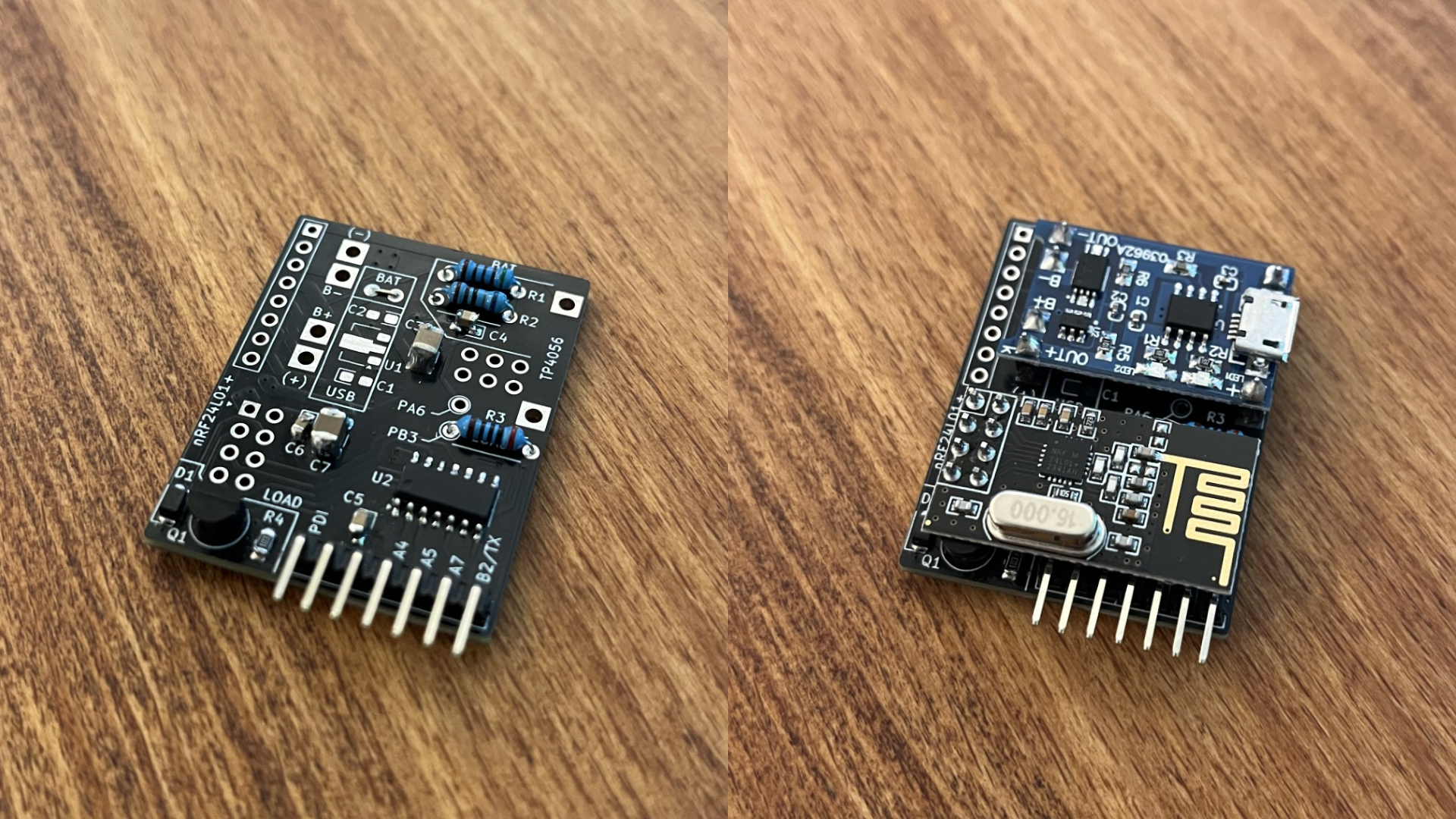
Hardware

With and without the TP4056 and nRF24L01+ modules. Dimensions 42mm x 31mm.
The picture shows a battery/solar-powered node.
hardware.jpg


Nodes

Nodes 1-10: Self watering plants

Uses a 3-5V waterpump and DIY capacative fluid-level sensor. See link below.
Liquid Level Sensing Using Capacitive-to-Digital Converters

The solar-powered variant uses the TP4056 to charge a Li-ion/LiPo battery.
While the USB variant skips that step and plugs directly into 5V (with 3.3V LDO onboard).

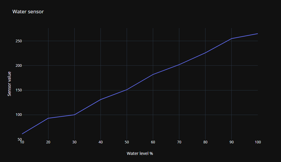
Node 1 water sensor linearity:

Sensor (ADC) reading vs water level in %.
water sensor

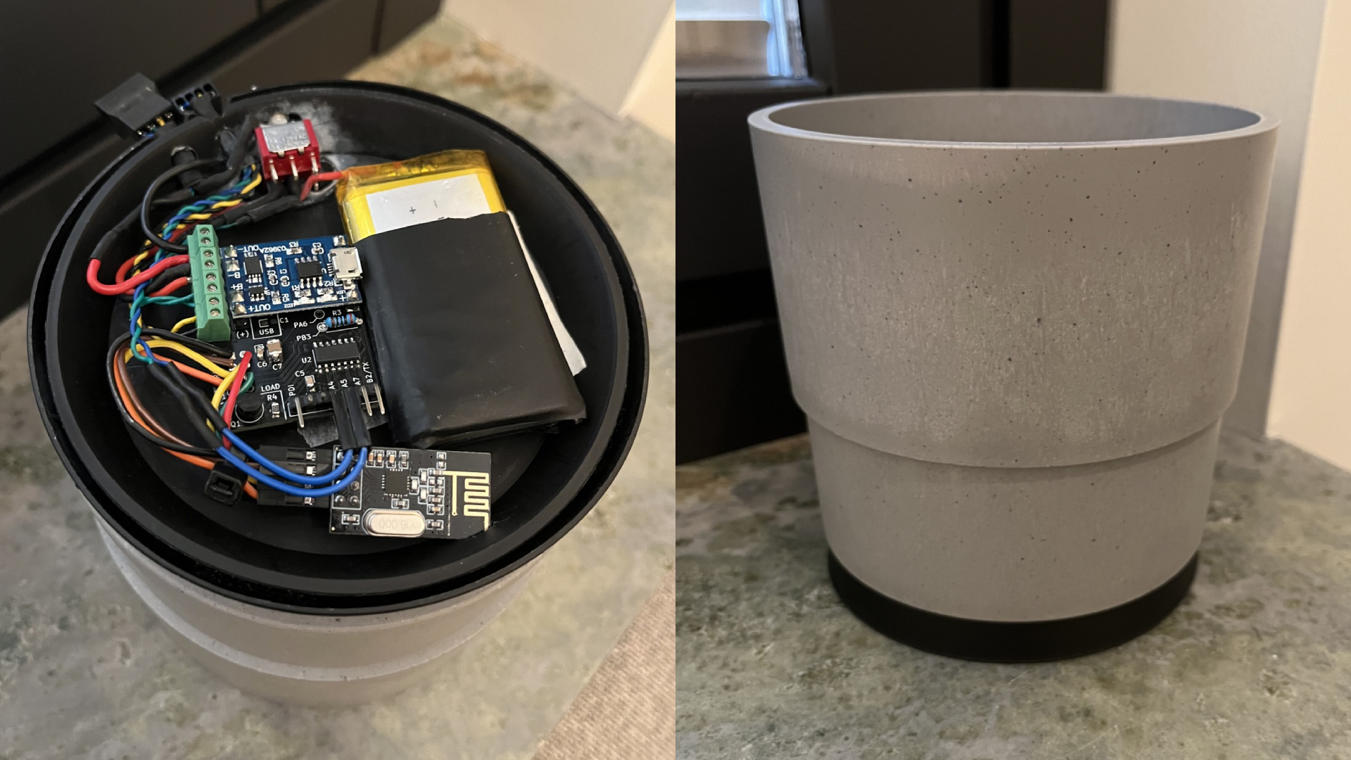
Node 1 hardware:

Most of the self-watering plant nodes have the hardware inside a plastic enclosure,
which I just hide behind the pots.
However, for node 1, I placed all electronics underneath for a pretty decent look.
node_1_hardware.jpg  

Node 11: Mocca Master controller

Uses a SG90 servo mounted internally to toggle the On/Off button,
and a hall-effect current sensor, to get the current state.

"Looks pretty neat when the button toggles all by itself :)"


Parts

24
QtyValueFootprintReferences
3100nFCapacitor_Tantalum_SMD:CP_EIA-2012-15_AVX-P_Pad1.30x1.05mm_HandSolderC4, C5, C6
21ufCapacitor_Tantalum_SMD:CP_EIA-2012-15_AVX-P_Pad1.30x1.05mm_HandSolderC1, C2
10-10K ?Resistor_THT:R_Axial_DIN0207_L6.3mm_D2.5mm_P7.62mm_HorizontalR8
110KResistor_SMD:R_0805_2012Metric_Pad1.20x1.40mm_HandSolderR4
110uFCapacitor_SMD:C_1210_3225Metric_Pad1.33x2.70mm_HandSolderC7
122uFCapacitor_SMD:C_1210_3225Metric_Pad1.33x2.70mm_HandSolderC3
15.1KResistor_THT:R_Axial_DIN0207_L6.3mm_D2.5mm_P7.62mm_HorizontalR1
16.8KResistor_THT:R_Axial_DIN0207_L6.3mm_D2.5mm_P7.62mm_HorizontalR2
1ATtiny84A-PPackage_SO:SOIC-14_3.9x8.7mm_P1.27mmU2
1Conn_01x06Connector_PinHeader_2.54mm:PinHeader_1x06_P2.54mm_VerticalJ6
1DDiode_SMD:D_SOD-123FD1
1MCP1700T-3302E/MB Package_TO_SOT_SMD:SOT-89-3U1
1NRF24L01_BreakoutRF_Module:nRF24L01_BreakoutnRF24L01+
1TO-92_InlinePackage_TO_SOT_THT:TO-92_InlineQ1
1~TP4045:TP4056-18650TP4056

The 18 most common of 24 parts.

Similar boards

  • 2 layers96.5 × 25.4 mmLed game, the printed circuit board in 3D

    Led game

    agalakhov/led-game

    Simple LED game for learning soldering.

    20 parts2MIT
  • 2 layers94 × 63.8 mmTinySensorv1, the printed circuit board in 3D

    TinySensorv1

    arcadien/tinySensor

    Firmware and generic board for low-power environment sensors

    45 parts2MIT
  • 2 layers55.2 × 40.6 mmSpectrum, the printed circuit board in 3D

    Spectrum

    jblang/ATtiny84A_spectrum

    ATtiny Spectrum Analyzer

    24 parts2
  • 2 layers35 × 28 mmVolvo240pcb, the printed circuit board in 3D

    Volvo240pcb

    pddenhar/Volvo_240_Info_Display

    OLED dashboard module for the Volvo 240 displaying battery voltage, speed, and RPM.

    18 parts2
  • 2 layers90 × 40 mmPlate, the printed circuit board in 3D

    Plate

    BryceVandegrift/hot-plate

    A DIY PCB hot plate that uses through hole components

    30 parts1CERN-OHL-W-2.0
  • 2 layers92 × 45 mmL6 - P2, the printed circuit board in 3D

    L6 - P2

    AhmedAtefNasr/PCB_Course-IMT_school

    Here's the repo for Assignments & projects of PCB course from IMT school

    49 parts
  • 2 layers46 × 66 mmDoor sensor schaltplan, the printed circuit board in 3D

    Door sensor schaltplan

    Brawn1/ATTiny-Door-Sensor

    Door Sensor Battery based with Attiny84 and HC-12 Sender

    19 parts

Questions

How big is the NRF node smd PCB?

It measures 32 × 41 mm and has 2 copper layers, 1.6 mm thick.

What parts does the NRF node smd use?

24 parts, built around the ATTINY84A-PU. The full list of its parts is on this page, with links to each part's symbol and footprint where PCBKit's library has them.

Where can I download the NRF node smd KiCad files?

From the Peppson/radio-nodes repository on GitHub, at the commit this page was made from: the board is _KiCad/NRF_node_smd.kicad_pcb and its schematic _KiCad/NRF_node_smd.kicad_sch. PCBKit opens the board in the browser, with nothing to install.

Can I use the NRF node smd design in my own project?

Its repository states no licence, so its author keeps all rights: ask Peppson before reusing the design.