2 layers99.5 × 99.5 mm
Misc PCB
kwiecinski/BMS-and-offgrid-photovoltaic-management-system
Project contains BMS for lead-acid batteries and ESP-based board used to pull information from EASUN offgrid inverter, energy meters and sensors.
152 parts3MIT

 pawel2000pl/LedDriverIoT1
IOT led driver dedicated for ESP32C3
IoT Led v1 is an open-source printed circuit board by pawel2000pl, from the pawel2000pl/LedDriverIoT repository on GitHub. It is a 2-layer board of 80 × 60 mm with 73 parts on 35 nets, routed with 488 tracks and 192 vias.
It is built around the ESP32-C3-WROOM-02-H4, MC34063AP and LD1117V33, with the AOI4184, AON7466 and IRF540N among its other parts. Its parts include 18 transistors, 14 resistors, 12 capacitors, 9 diodes and 4 connectors. It belongs with the home automation and IoT boards and the ESP32 and RISC-V boards of this library.


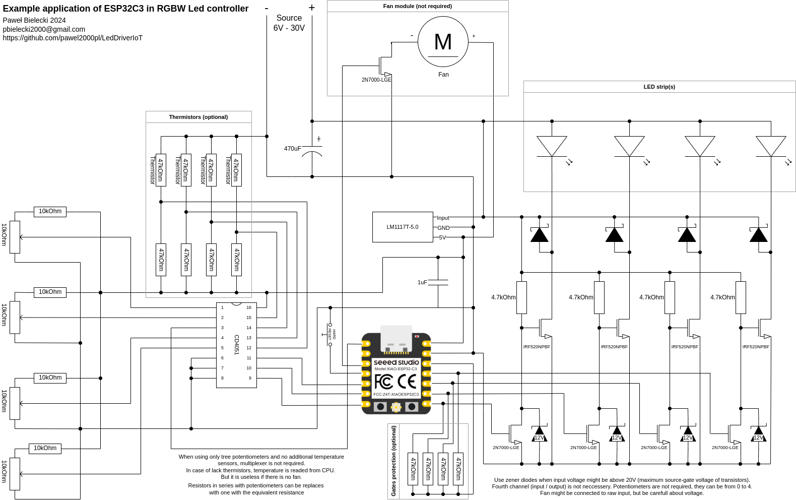
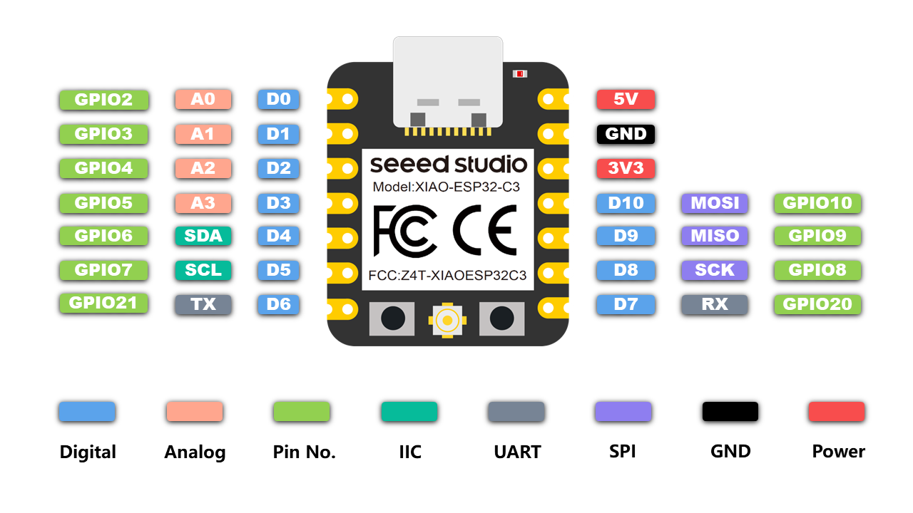
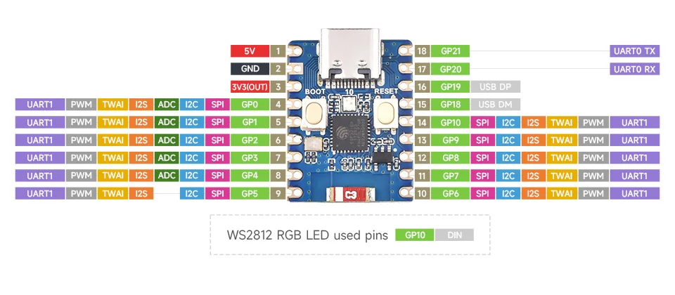
Project was designed for XIAO ESP32C3 and Waveshare ESP32C3-Zero.
Compilable with Arduino and ESP-IDF.
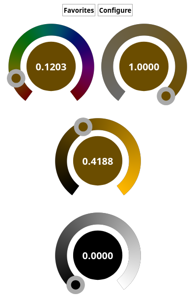
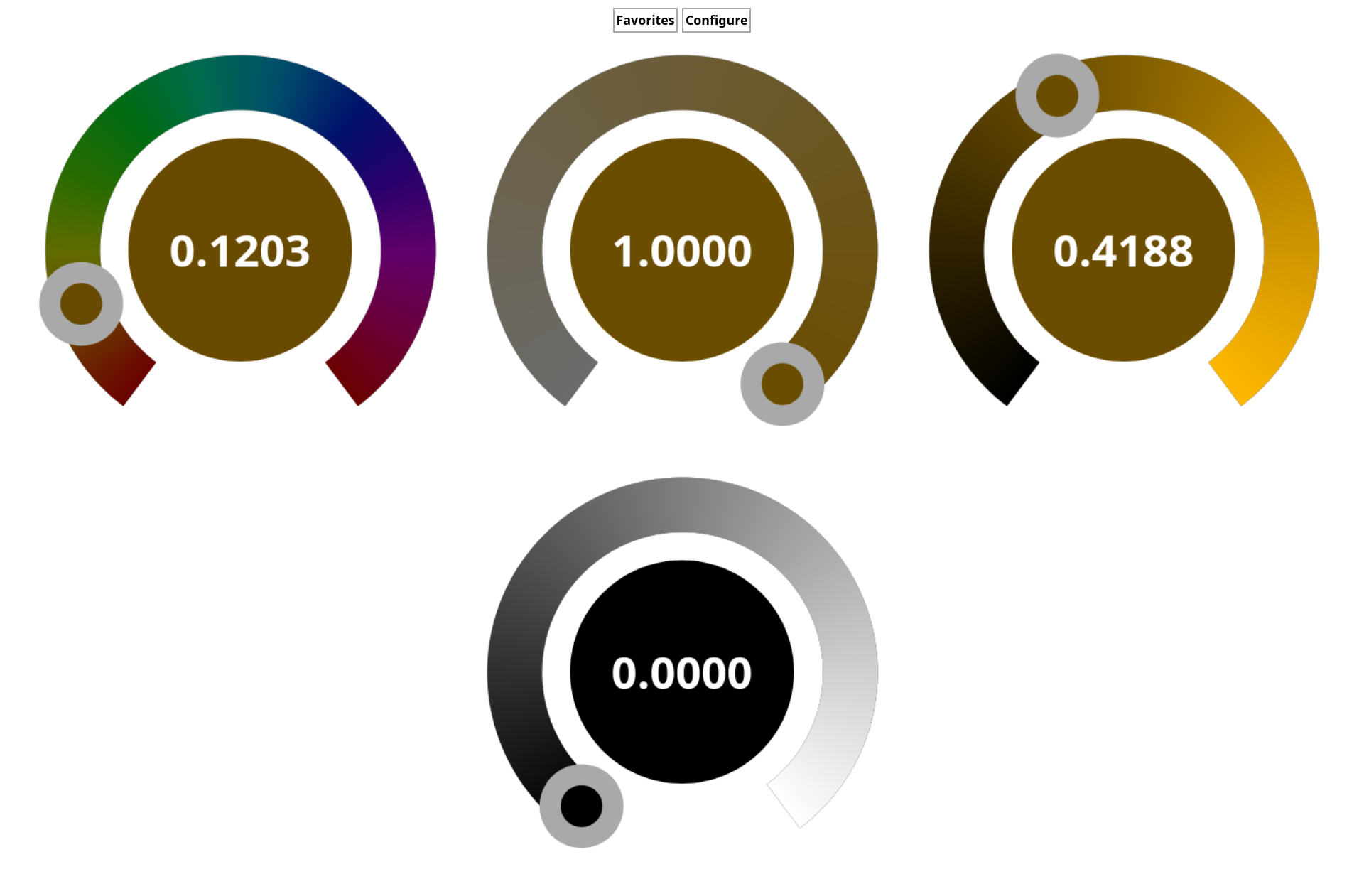
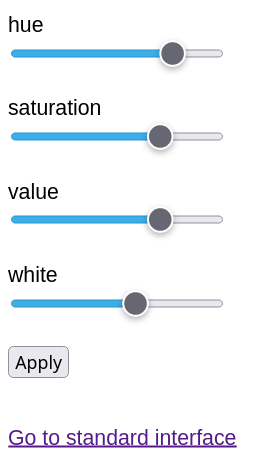

docker build -t led_driver_idf -f Idf.Dockerfile . && docker run -it -p 8000:8000 led_driver_idf
# or
# docker build -t led_driver_arduino -f Arduino.Dockerfile . && docker run -it -p 8000:8000 led_driver_arduino
then open http://0.0.0.0:8000 in your browser and download a binary file.
You can aslo run a script which builds the image, runs the container, downloads this file automatically and removes the container:
./compile_with_docker.shThe file iot-led-driver.bin can be uploaded on Configuration page in Update tab.
Before the compilation, it is required to compile resources to .cpp and .h files. It is also required after any modification of any file in the resources directory.
To compile resources, execute in the project directory:
python3 ./compilation_utils/compile_resources.pyOn the first usage of microcontroller you should run idf.py erase_flash to ensure that flash partitions will be initialized properly.
Run idf.py build in the project directory.
Open the file main/main.ino in Arduino. Set the following parameters:
The runtime statistics are available on /statistics.txt endpoint.
The last system statistics:
=== Tasks info ===
Name             |        Ticks | CPU % | Free stack |  Stack ptr
-----------------+--------------+-------+------------+------------
IDLE             |    390961538 |   85% |       1240 | 0x3fca6ef8
loopTask         |     34119316 |    7% |       3992 | 0x3fca87a8
knobs            |     20251982 |    4% |       1488 | 0x3fcb55d0
wifi             |      2405020 |    0% |       2128 | 0x3fcaedb0
tiT              |      1366588 |    0% |       2744 | 0x3fcaad80
animations       |       790686 |    0% |       1568 | 0x3fcb68a0
esp_timer        |       786223 |    0% |       3672 | 0x3fca4be8
shutdown         |       472535 |    0% |       1720 | 0x3fcb5f38
sys_evt          |         8169 |    0% |       2152 | 0x3fcac204
mdns             |         5225 |    0% |       3116 | 0x3fcb0fe4
arduino_events   |         4456 |    0% |       2836 | 0x3fcad03c
Tmr Svc          |            8 |    0% |       1792 | 0x3fca7660


=== Heap info ===
Total size:             247524
Minimum free heap:      111860  ( 45% )
Total free bytes:       155624  ( 62% )
Total allocated bytes:   91900  ( 37% )
Largest free block:     114688  ( 46% )
Blocks free:                10
Blocks allocated: 405LedDriver and connect to them with ledDriver password. Then type in browser http://192.168.1.1.LedDriver, create it (as a Hotspot) on your phone with password ledDriver and restart the driver. The Hotspot must work with WiFi 5 or an older version.Unfortunately, there is no way to predetermine driver's IP address in a network other than its own AccessPoint.
The driver supports mDNS technology. After connecting to your network, try to enter the driver's hostname with suffix .local (f.e.: http://led-driver.local) in an address bar of a browser. Sometimes this technology requires a while to be detected by other devices in the network.
In case of using https protocol you may be warned about danger of self signed or untrusted certificate.
Skip it and/or add this certificate to exceptions.
Select one of four possible configurations:
Each configuration might be modified by disconnecting potentiometers or removing thermistors. The software matches pins automatically.
...and possible hardware configurations
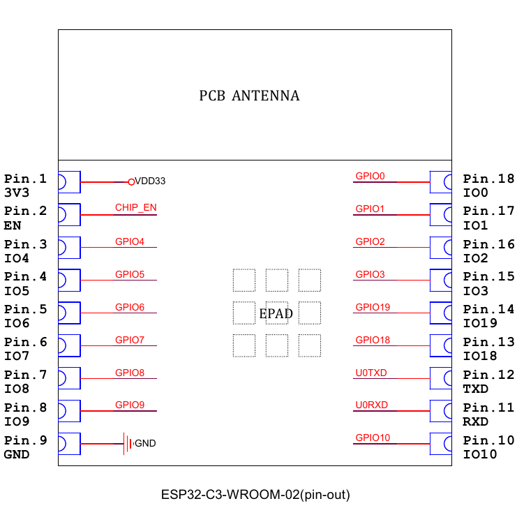
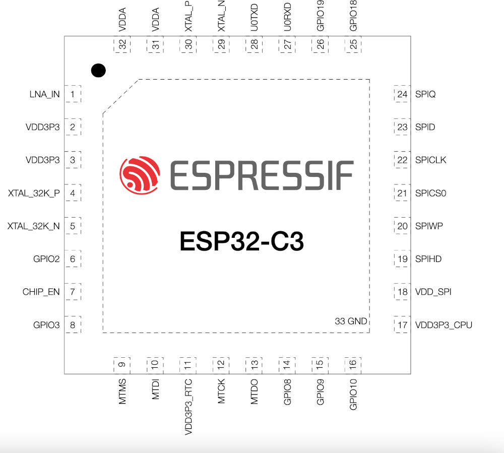
| Pin | Name | XIAO | Waveshare | Multiplexer #1 | Multiplexer #2 | Multiplexer #3 | Simple #1 | Simple1 #2 | Comment |
|---|---|---|---|---|---|---|---|---|---|
| 1 | LNA_IN | ANT | ANT | ANT | ANT | ANT | ANT | ANT | |
| 2 | VDD3P3 | VCC 3,3 | VCC 3,3 | VCC 3,3 | VCC 3,3 | VCC 3,3 | VCC 3,3 | VCC 3,3 | |
| 3 | VDD3P3 | VCC 3,3 | VCC 3,3 | ||||||
| 4 | XTAL_32K_P | internal | GP0 | Cannot be connected during the booting (H/Z) | |||||
| 5 | XTAL_32K_N | internal | GP1 | Cannot be connected during the booting (H/Z) | |||||
| 6 | GPIO2 | D0 | GP2 | Mult COM | Mult COM | Mult COM | Potentiometer 0 | Potentiometer 0 | |
| 7 | EN | EN | |||||||
| 8 | GPIO3 | D1 | GP3 | H/Z | GND | UP | Potentiometer 1 | Potentiometer 1 | |
| 9 | MTMS | D2 | GP4 | FAN | FAN | FAN | Potentiometer 2 | Potentiometer 2 | |
| 10 | MTDI | D3 | GP5 | FLASH RST | FLASH RST | FLASH RST | FLASH RST | LED OUT 0 | |
| 11 | VDD3P3_RTC | VCC 3,3 | VCC 3,3 | ||||||
| 12 | MTCK | D4 | GP6 | Mult. SEL0 | Mult. SEL0 | Mult. SEL0 | FAN (short them all) | LED OUT 1 | |
| 13 | MTDO | D5 | GP7 | Mult. SEL1 | Mult. SEL1 | Mult. SEL1 | FAN (short them all) | LED OUT 2 | |
| 14 | GPIO8 | D8 | GP8 | LED OUT 1 | LED OUT 1 | LED OUT 1 | LED OUT 1 | LED OUT 3 | |
| 15 | GPIO9 | D9 | GP9 | LED OUT 2 | LED OUT 2 | LED OUT 2 | LED OUT 2 | FLASH RST | Pulled-up during the booting (internal) |
| 16 | GPIO10 | D10 | GP10 | LED OUT 3 | LED OUT 3 | LED OUT 3 | LED OUT 3 | FAN (short them all) | |
| 17 | VDD3P3_CPU | VCC 3,3 | VCC 3,3 | ||||||
| 18 | VDD_SPI | VDD SPI | VDD SPI | ||||||
| 19 | SPIHD | internal | internal | ||||||
| 20 | SPIWP | internal | internal | ||||||
| 21 | SPICS0 | internal | internal | ||||||
| 22 | SPICLK | internal | internal | ||||||
| 23 | SPID | internal | internal | ||||||
| 24 | SPIQ | internal | internal | ||||||
| 25 | GPIO18 | internal | ESP_USB_DP | ||||||
| 26 | GPIO19 | internal | ESP_USB_DM | ||||||
| 27 | U0RXD | D7 | GP20 | LED OUT 0 | LED OUT 0 | LED OUT 0 | LED OUT 0 | ||
| 28 | U0TXD | D6 | GP21 | Mult. SEL2 | Mult. SEL2 | Mult. SEL2 | FAN (short them all) | FAN (short them all) | |
| 29 | XTAL_N | internal | internal | ||||||
| 30 | XTAL_P | internal | internal | ||||||
| 31 | VDDA | internal | internal | ||||||
| 32 | VDDA | internal | internal | ||||||
| 33 | GND | GND | GND | ||||||
| Mult. Ch0 | Thermistor 0 | Potentiometer 0 | Thermistor 0 | ||||||
| Mult. Ch1 | Thermistor 1 | Potentiometer 1 | Thermistor 1 | ||||||
| Mult. Ch2 | Thermistor 2 | Potentiometer 2 | Thermistor 2 | ||||||
| Mult. Ch3 | Thermistor 3 | Potentiometer 3 | Thermistor 3 | ||||||
| Mult. Ch4 | Potentiometer 0 | ||||||||
| Mult. Ch5 | Potentiometer 1 | ||||||||
| Mult. Ch6 | Potentiometer 2 | ||||||||
| Mult. Ch7 | Potentiometer 3 |
| Qty | Value | Footprint | References |
|---|---|---|---|
| 7 | 470u | Capacitor_THT:CP_Radial_D5.0mm_P2.50mm | C2, C4, C6, C7, C8, C9, C10 |
| 6 | R | Resistor_THT:R_Axial_DIN0207_L6.3mm_D2.5mm_P10.16mm_Horizontal | R5, R7, R8, R9, R10, R14 |
| 5 | 1n5819 | Diode_THT:D_DO-41_SOD81_P10.16mm_Horizontal | D1, D3, D5, D6, D8 |
| 5 | 2N7000/2N5550 | Package_TO_SOT_THT:TO-92_Inline | Q4, Q8, Q12, Q16, Q17 |
| 4 | 1u | Capacitor_THT:C_Disc_D3.0mm_W2.0mm_P2.50mm | C1, C3, C11, C12 |
| 4 | AOI4184 | Package_TO_SOT_THT:TO-251-3_Vertical | Q3, Q7, Q11, Q15 |
| 4 | AON7466 | inne:AON7466 | Q1, Q5, Q9, Q13 |
| 4 | D_Zener | Diode_THT:D_DO-41_SOD81_P10.16mm_Horizontal | D2, D4, D7, D9 |
| 4 | IRF540N | Package_TO_SOT_THT:TO-220-3_Vertical | Q2, Q6, Q10, Q14 |
| 4 | Inv | Resistor_THT:R_Axial_DIN0207_L6.3mm_D2.5mm_P10.16mm_Horizontal | R1, R6, R11, R13 |
| 4 | Non-Inv | PCM_SparkFun-Jumper:Jumper_2_NO_NoSilk | JP1, JP5, JP6, JP8 |
| 3 | 10k | Potentiometer_THT:Potentiometer_Alps_RK163_Single_Horizontal | RV1, RV2, RV3 |
| 3 | Red. to 2.5V | Resistor_THT:R_Axial_DIN0207_L6.3mm_D2.5mm_P10.16mm_Horizontal | R2, R3, R4 |
| 1 | 2N5550 | Package_TO_SOT_THT:TO-92_Inline | Q18 |
| 1 | 47p-470p | Capacitor_THT:C_Disc_D3.0mm_W2.0mm_P2.50mm | C5 |
| 1 | 47u-470u | Inductor_THT:L_Axial_L5.3mm_D2.2mm_P2.54mm_Vertical_Vishay_IM-1 | L1 |
| 1 | BOOT/FLASH RST | PCM_SparkFun-Jumper:Jumper_2_NO_NoSilk | JP7 |
| 1 | Barrel_Jack_PTH_Slot | PCM_SparkFun-Connector:Barrel_Jack_PTH_Slot | J3 |
| 1 | ESP32-C3-WROOM-02 | RF_Module:ESP32-C3-WROOM-02 | U3 |
| 1 | FAN | Connector_PinSocket_2.54mm:PinSocket_2x02_P2.54mm_Vertical | J4 |
| 1 | LD1117V33 | Package_TO_SOT_THT:TO-220-3_Vertical | U1 |
| 1 | LEDs | Connector_PinSocket_2.54mm:PinSocket_2x05_P2.54mm_Vertical | J1 |
| 1 | MC34063AP | Package_DIP:DIP-8_W7.62mm | U2 |
| 1 | PULLUP | Resistor_THT:R_Axial_DIN0207_L6.3mm_D2.5mm_P10.16mm_Horizontal | R12 |
| 1 | Pulse+Linear | PCM_SparkFun-Jumper:Jumper_2_NO_NoSilk | JP3 |
| 1 | RST | PCM_SparkFun-Jumper:Jumper_2_NO_NoSilk | JP9 |
| 1 | Skip linear | PCM_SparkFun-Jumper:Jumper_2_NO_NoSilk | JP2 |
| 1 | Skip pulse | PCM_SparkFun-Jumper:Jumper_2_NO_NoSilk | JP4 |
| 1 | USB | Connector_PinHeader_2.54mm:PinHeader_1x03_P2.54mm_Vertical | J2 |
It measures 80 × 60 mm and has 2 copper layers, 1.6 mm thick.
73 parts, built around the ESP32-C3-WROOM-02-H4, MC34063AP, LD1117V33 and AOI4184. The full list of its parts is on this page, with links to each part's symbol and footprint where PCBKit's library has them.
From the pawel2000pl/LedDriverIoT repository on GitHub, at the commit this page was made from: the board is doc/example_board/IoT_Led_v1.kicad_pcb and its schematic doc/example_board/IoT_Led_v1.kicad_sch. PCBKit opens the board in the browser, with nothing to install.
Its repository states no licence, so its author keeps all rights: ask pawel2000pl before reusing the design.
kwiecinski/BMS-and-offgrid-photovoltaic-management-system
Project contains BMS for lead-acid batteries and ESP-based board used to pull information from EASUN offgrid inverter, energy meters and sensors.

KerimAltuntecim/esp32-pcb-control-system
ESP32-C3 PCB control system with Nextion HMI, motor, sensor and power-driver interfaces.


fabianmink/MarbleAccelerator
An accelerator / coilgun for metallic marbles


cookiemonsternz/fallout-badge
A badge with holes for mounting to a lanyard, containing within a full miniature analogue synthesizer / sequencer.