4 layers62.1 × 83.8 mm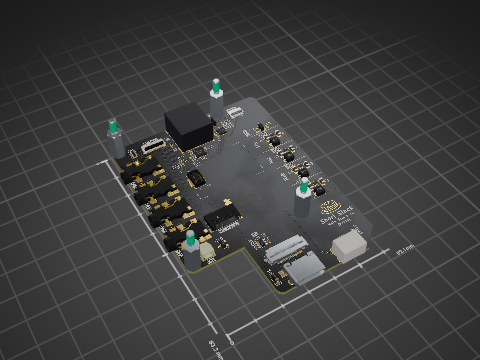
Ss main board
loopj/short-stack
World's Smallest Nintendo Wii, using a trimmed motherboard and custom stacked PCBs
69 parts804

 pavel-d/mail-beacon1
The Mailbox Beacon is a device that detects when a new letter or package has been delivered to your mailbox using a reed switch.
Mailbox beacon is an open-source printed circuit board by pavel-d, from the pavel-d/mail-beacon repository on GitHub. It is a 2-layer board of 29 × 48.5 mm with 28 parts on 32 nets, routed with 152 tracks and 25 vias.
It is built around the ATTINY1616-MN and SPX3819M5-L-3-3. Its parts include 4 resistors, 3 capacitors, 3 ICs, 3 connectors and 2 diodes. It belongs with the radio and wireless boards and the AVR (ATmega, ATtiny) boards of this library.


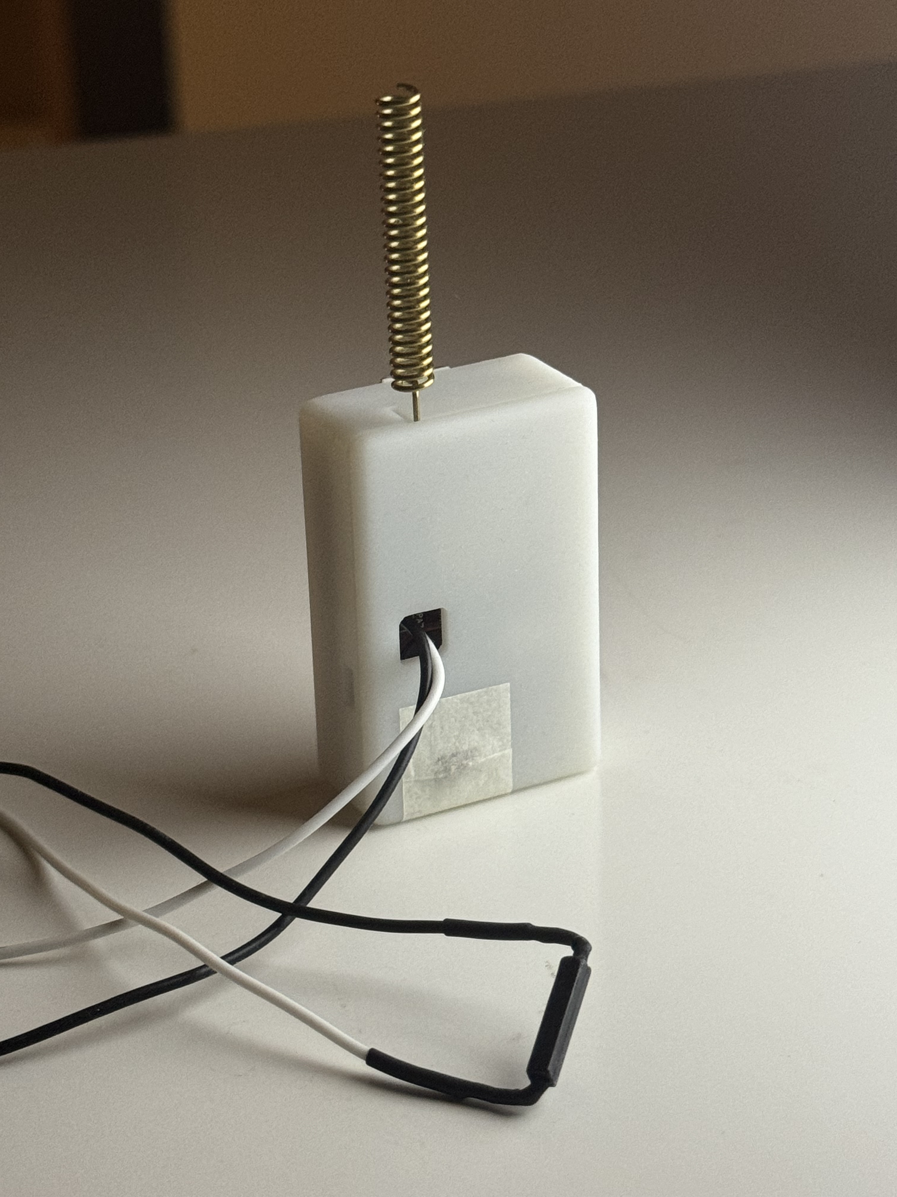
The Mailbox Beacon is a device that detects when a new letter or package has been delivered to your mailbox using a reed switch. It sends a signal to your LoRa gateway, then the gateway sends a message via WiFi to MQTT server. It's designed to integrate with HomeAssistant, but can theoretically work with anything that supports MQTT based sensors.
Reed switch (or any other kind of contact switch) must be connected either to PA4 or PA7 pins and to the GND. Pins have internal pull-ups enabled and are "active low", so the switch must pull the pin to the ground when circuit is closed. Both pins have interrupts attached, microcontroller will send a message to the gateway when the logic level changes.
TEST button also has an interrupt attached and can be used to test the setup.
Power LED has a jumper that can be cut to reduce the power consumption.
The beacon sends the battery voltage (in milivolts) in every LoRa packet, so that you know when you need to re-charge the battery.
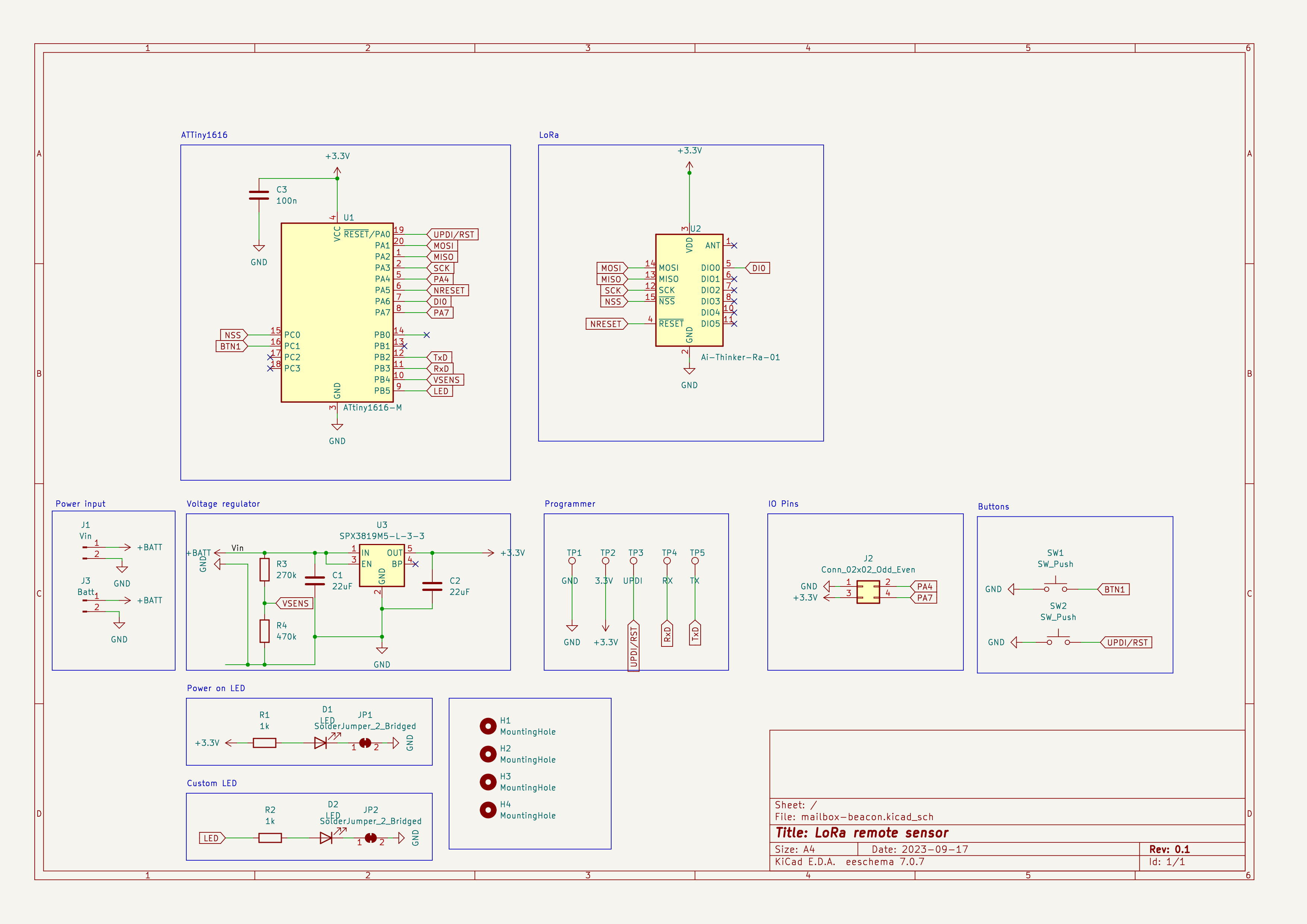
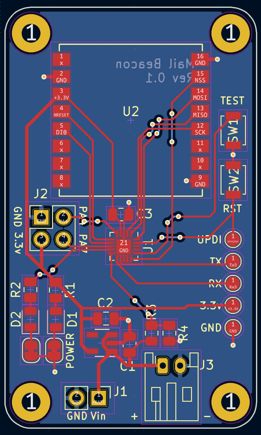
| Qty | Value | Footprint | References |
|---|---|---|---|
| 4 | MountingHole | MountingHole:MountingHole_2.2mm_M2_Pad | H1, H2, H3, H4 |
| 2 | 1k | Resistor_SMD:R_0805_2012Metric | R1, R2 |
| 2 | 22uF | Capacitor_SMD:C_0805_2012Metric | C1, C2 |
| 2 | LED | LED_SMD:LED_0805_2012Metric | D1, D2 |
| 2 | SW_Push | Button_Switch_SMD:SW_SPST_B3U-1000P | SW1, SW2 |
| 2 | SolderJumper_2_Bridged | Jumper:SolderJumper-2_P1.3mm_Bridged_RoundedPad1.0x1.5mm | JP1, JP2 |
| 1 | 100n | Capacitor_SMD:C_0805_2012Metric | C3 |
| 1 | 10k | Resistor_SMD:R_0805_2012Metric | R3 |
| 1 | 20k | Resistor_SMD:R_0805_2012Metric | R4 |
| 1 | 3.3V | TestPoint:TestPoint_Pad_D1.5mm | TP2 |
| 1 | ATtiny1616-M | Package_DFN_QFN:VQFN-20-1EP_3x3mm_P0.4mm_EP1.7x1.7mm | U1 |
| 1 | Ai-Thinker-Ra-01 | RF_Module:Ai-Thinker-Ra-01-LoRa | U2 |
| 1 | Batt | Connector_JST:JST_PH_S2B-PH-K_1x02_P2.00mm_Horizontal | J3 |
| 1 | Conn_02x02_Odd_Even | Connector_PinHeader_2.54mm:PinHeader_2x02_P2.54mm_Vertical | J2 |
| 1 | GND | TestPoint:TestPoint_Pad_D1.5mm | TP1 |
| 1 | RX | TestPoint:TestPoint_Pad_D1.5mm | TP4 |
| 1 | SPX3819M5-L-3-3 | Package_TO_SOT_SMD:SOT-23-5 | U3 |
| 1 | TX | TestPoint:TestPoint_Pad_D1.5mm | TP5 |
| 1 | UPDI | TestPoint:TestPoint_Pad_D1.5mm | TP3 |
| 1 | Vin | Connector_PinHeader_2.54mm:PinHeader_1x02_P2.54mm_Vertical | J1 |
loopj/short-stack
World's Smallest Nintendo Wii, using a trimmed motherboard and custom stacked PCBs


kieraneglin/hexagon-art
A passive breakout board: two lever-terminal inputs, three JST XH outputs, all six conductors (RX bus, two spares, +12V, GND, +5V) paralleled straight across. No active components, no regulation, nothing to configure.

engineerbo/flashlight-dev-hw
This repository contains design files for the development board for a flashlight boost driver. The test firmware can be found in the firmware repository.

hojadurdy/Flux_Capacitor_Micro
A tiny (36mm x 29mm) pin badge and keychain PCB version of Flux Capacitor featuring 25 animated LEDs that animate to create the “fluxxing” effect.


It measures 29 × 48.5 mm and has 2 copper layers, 4.69 mm thick.
28 parts, built around the ATTINY1616-MN and SPX3819M5-L-3-3. The full list of its parts is on this page, with links to each part's symbol and footprint where PCBKit's library has them.
From the pavel-d/mail-beacon repository on GitHub, at the commit this page was made from: the board is pcb/mailbox-beacon.kicad_pcb and its schematic pcb/mailbox-beacon.kicad_sch. PCBKit opens the board in the browser, with nothing to install.
Its repository states no licence, so its author keeps all rights: ask pavel-d before reusing the design.