2 layers149 × 45 mm

 hojadurdy/Flux_Capacitor_Micro6
A tiny (36mm x 29mm) pin badge and keychain PCB version of Flux Capacitor featuring 25 animated LEDs that animate to create the “fluxxing” effect.
Flux Capacitor Micro Pin Badge is an open-source printed circuit board by hojadurdy, from the hojadurdy/Flux_Capacitor_Micro repository on GitHub. It is a 2-layer board of 29 × 36 mm with 48 parts on 21 nets, routed with 444 tracks and 18 vias.
It is built around the ATTINY1616-MN, CR2032 and TL 8. Its parts include 25 diodes, 5 resistors, 3 capacitors, 2 switches and 1 IC. It belongs with the lEDs and displays boards and the AVR (ATmega, ATtiny) boards of this library.


A tiny (36mm x 29mm) pin badge and keychain PCB version of Flux Capacitor featuring 25 animated LEDs that animate to create the “fluxxing” effect. It’s 100% decorative, it doesn’t actually let you travel through time when worn around the neck.
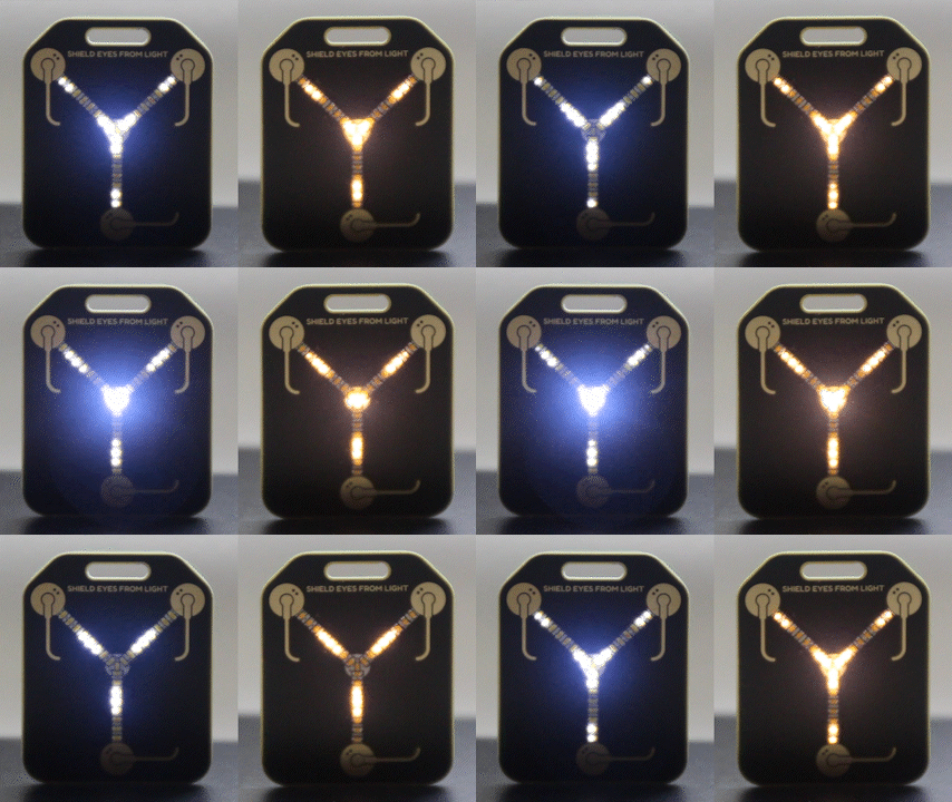
This tiny Flux Capacitor is controlled by a Microchip ATtiny1616 microcontroller. Thankfully this board has a much lower power requirement than the silkscreen indicates on the back, and skips along, sipping power from the single CR2016/LIR2016 coin cell battery (instead of plutonium or a lightning strike), slipped into the rear mounted coin cell holder. By using PWM (Pulse Width Modulation) pins for 8 channels of 3 paralleled LEDs, different animation patterns are generated for the fluxxxing effect. In settings mode, users are able change between 8 different animation, speed and LED brightness.
Below you can see the thickness comparison of V3 on the left and V4 on the right.

CR2016 (Non-Rechargeable) with average of 90 mAh battery capacity.
LIR2016 (Rechargeable) with average of 20 mAh battery capacity.
To begin with, turn on the device by pressing power button. In order to enter settings mode just hold the set button for 1 second. If all of the LEDs flashes twice, you are successfully entered settings mode.

After the LEDs flash you will see that only single LED remains on. That single LED shows which animation is selected. To change that, just short press the set button and the LED should start shifting from inner to outer LED with each press. After selecting the preferred animation, hold the set button for 1 second to save. LEDs should flash twice to confirm.
Next setting is animation speed. To change the animation speed, just short press the set button to increase the speed. LEDs will turn on from inner to outer to indicate animation speed. At maximum speed all LEDs should be on. Hold the set button for 1 second to save animation speed. LEDs should flash twice to confirm.
Last setting is LED brightness. Same as before to change the brightness just short press the set buttonto increase the brightness. LEDs will turn on from inner to outer to indicate brightness level. At maximum brightness all LEDs should be on. Hold the set button for 1 second to save brightness setting. LEDs should flash twice to confirm and device should exit the setting mode. LEDs should start animating.
If you short press the button with gear icon during normal operation, device initiates engage mode. LEDs start to animate faster with much brighter center beam as shown in the video below.
Only CR2016 or LIR2016 batteries are compatible. If you prefer to use larger CR2032 or LIR2032 batteries, message me from store page. I will change the battery holder to a larger one. Also batteries are not included due to shipping restrictions.

| Qty | Value | Footprint | References |
|---|---|---|---|
| 7 | LOGO | LOGO | G***, G***, G***, G***, G***, G***, G*** |
| 3 | 100nF | HDMod_Capacitor_SMD:C_0402_1005Metric | C1, C2, C3 |
| 2 | 10K | HDMod_Resistor_SMD:R_0402_1005Metric | R2, R3 |
| 2 | 510 | HDMod_Resistor_SMD:R_0402_1005Metric | R1, R4 |
| 1 | 0 | HDMod_Resistor_SMD:R_0402_1005Metric | R5 |
| 1 | ATtiny1616-M | HDMod_Package_DFN_QFN:VQFN-20-1EP_3x3mm_P0.4mm_EP1.7x1.7mm | U1 |
| 1 | BM1 | HDMod_LED_SMD:LED_0402_1005Metric | D21 |
| 1 | BM2 | HDMod_LED_SMD:LED_0402_1005Metric | D22 |
| 1 | BM3 | HDMod_LED_SMD:LED_0402_1005Metric | D23 |
| 1 | BM4 | HDMod_LED_SMD:LED_0402_1005Metric | D24 |
| 1 | BM5 | HDMod_LED_SMD:LED_0402_1005Metric | D25 |
| 1 | BM6 | HDMod_LED_SMD:LED_0402_1005Metric | D26 |
| 1 | BM7 | HDMod_LED_SMD:LED_0402_1005Metric | D27 |
| 1 | BM8 | HDMod_LED_SMD:LED_0402_1005Metric | D28 |
| 1 | CR2032 | HDMod_Battery_Holder_SMD:MY-2016-02 | BT1 |
| 1 | Flash | HDMod_LED_SMD:LED_0402_1005Metric | D1 |
| 1 | G*** | svg2mod | svg2mod |
| 1 | G*** | kibuzzard-63026A3F | kibuzzard-63026A3F |
| 1 | On/Off | HDMod_Switch_SMD:K2-1809SN-D4DW-06 | SW1 |
| 1 | Set | HDMod_Switch_SMD:K2-1809SN-D4DW-06 | SW2 |
| 1 | TL1 | HDMod_LED_SMD:LED_0402_1005Metric | D11 |
| 1 | TL2 | HDMod_LED_SMD:LED_0402_1005Metric | D12 |
| 1 | TL3 | HDMod_LED_SMD:LED_0402_1005Metric | D13 |
| 1 | TL4 | HDMod_LED_SMD:LED_0402_1005Metric | D14 |
| 1 | TL5 | HDMod_LED_SMD:LED_0402_1005Metric | D15 |
| 1 | TL6 | HDMod_LED_SMD:LED_0402_1005Metric | D16 |
| 1 | TL7 | HDMod_LED_SMD:LED_0402_1005Metric | D17 |
| 1 | TL8 | HDMod_LED_SMD:LED_0402_1005Metric | D18 |
| 1 | TR1 | HDMod_LED_SMD:LED_0402_1005Metric | D31 |
| 1 | TR2 | HDMod_LED_SMD:LED_0402_1005Metric | D32 |
| 1 | TR3 | HDMod_LED_SMD:LED_0402_1005Metric | D33 |
| 1 | TR4 | HDMod_LED_SMD:LED_0402_1005Metric | D34 |
| 1 | TR5 | HDMod_LED_SMD:LED_0402_1005Metric | D35 |
| 1 | TR6 | HDMod_LED_SMD:LED_0402_1005Metric | D36 |
| 1 | TR7 | HDMod_LED_SMD:LED_0402_1005Metric | D37 |
| 1 | TR8 | HDMod_LED_SMD:LED_0402_1005Metric | D38 |
| 1 | UPDI_PAD | HDMod_Testing_and_Programming_PAD:PogoPad_1x03_P1.27mm | J1 |
The 47 most common of 48 parts.


dragonlock2/kicadboards
Offsite backup for the miscellaneous KiCad boards that don't fit elsewhere
loopj/short-stack
World's Smallest Nintendo Wii, using a trimmed motherboard and custom stacked PCBs


kieraneglin/hexagon-art
A passive breakout board: two lever-terminal inputs, three JST XH outputs, all six conductors (RX bus, two spares, +12V, GND, +5V) paralleled straight across. No active components, no regulation, nothing to configure.

engineerbo/flashlight-dev-hw
This repository contains design files for the development board for a flashlight boost driver. The test firmware can be found in the firmware repository.
It measures 29 × 36 mm and has 2 copper layers, 0.8 mm thick.
48 parts, built around the ATTINY1616-MN, CR2032 and TL 8. The full list of its parts is on this page, with links to each part's symbol and footprint where PCBKit's library has them.
From the hojadurdy/Flux_Capacitor_Micro repository on GitHub, at the commit this page was made from: the board is PCB/Flux_Capacitor_Micro_Pin_Badge.kicad_pcb and its schematic PCB/Flux_Capacitor_Micro.kicad_sch. PCBKit opens the board in the browser, with nothing to install.
Its repository states no licence, so its author keeps all rights: ask hojadurdy before reusing the design.