
4 layers42 × 42 mm
 ParksDevelopment/2Pocket22
Tiny 36 key keyboard for a competition
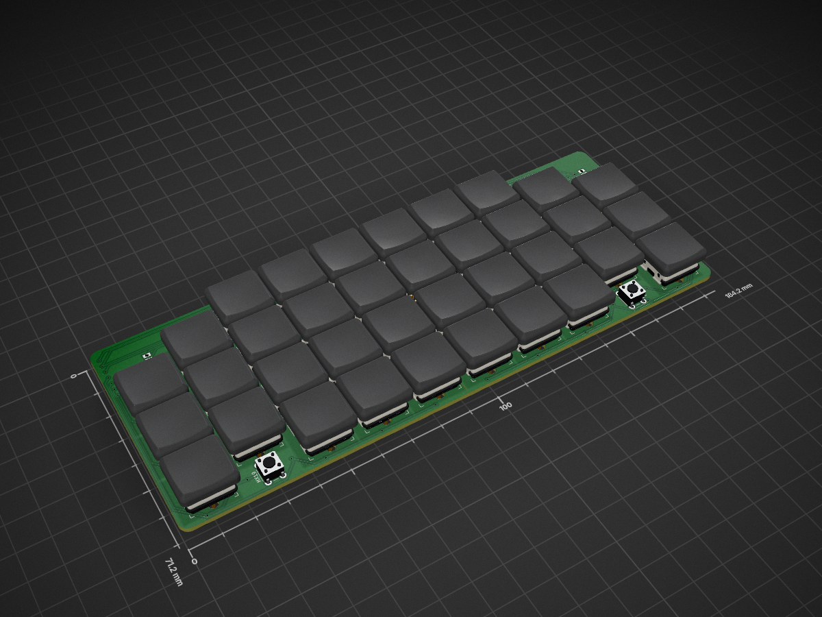
2Pocket is an open-source printed circuit board by ParksDevelopment, from the ParksDevelopment/2Pocket repository on GitHub. It is a 2-layer board of 184.2 × 71.2 mm with 95 parts on 89 nets, routed with 492 tracks and 81 vias.
It is built around the ADXL345-EP. Its parts include 39 diodes, 6 capacitors, 4 resistors, 4 ICs and 4 connectors. It belongs with the keyboards and input boards and the nRF52 and nRF5x boards of this library.

The 2Pocket is a pocket keyboard originally created for the Pocket Keyboard Design Contest. As such it was designed to meet the criteria of the contest as closely as possible while still being a practical keyboard for daily use. The feature list of the 2Pocket is pretty fleshed out including:
The idea behind the board was to create something that you can put in your pocket, ie fitting the bounding box, but does not force you to make any compromises to your work flow. I work a full time job as an software engineer and use a 36 key layout called Miryoku so it was important to me above all else to fit that standard so 36 keys was a must for me. I am able to hit 85 words per minute on it in monkey type 60 tests which is slower than my peak on a normal keyboard of 100 but definetly far from unpractical. Another key requirement for me was bluetooth. If this would be a pocket board then I would need it to be easier to bring places than my normal keyboard. The size helps but keeping it wireless allows me to pick it up on the way out the door or throw it in my bag without any fear of not having the necessary parts to make it run. Finally I wanted to play into the pocket part of the challenge which lead to the on board ADXL345. If I plan on keeping the board in my pocket It is already in the prime position to track my steps, and by mapping a button press to output my number of steps on the screen I am able to quickly see where I am at on the given day or trip. It gives me a great reason to still carry the board around even if I am not sure it will come in handy. Its not as accurate as a smart watch or even a smartphone but it gets pretty close and I am continuing to improve the step counting algorithem and features.
I will briefly explain below how to reproduce the board as well as discuss improvements that could be made in the future on the project in each area so. The production of the board is reletively simple, but will require either a 3D printer or ordering the case parts through a provider. I also chose to solder some parts and order the board with other parts soldered on. If you have a soldering station I would recommend you do the same but you can choose whatever works best for you. Below is the parts list which does not inclued the pcb or the case which will be discussed later:
| Part Name | Quantity | Solder by hand |
|---|---|---|
| Ceramic Capacitors 1uF | 4 | NO |
| Tantalum Capacitors 10uF | 2 | NO |
| ADXL345 | 2 | NO |
| 1N4148 Diode | 38 | NO |
| 4.7 k oHm Resistor | 4 | NO |
| 2 pin Jst socket | 2 | YES |
| 6 mm push button switches | 2 | YES |
| Choc hotswap sockets | 36 | YES |
| Xiao NRF52840 | 2 | YES |
| EEMB Lithium Polymer Battery 3.7V 1100mAh | 2 | DNA |
most of these the brand doesn't matter but the case is modeled to fit this specific battery so if you would like to use a different battery you need to make some modifications.
The PCB has a footprint of 185mm x 71mm x 1.6mm which does not give a ton of room for the case but it is hard to scale it down much without giving up keys or making the wiring much more complicated. To order the case go to the PCB folder in this repo and then go to the production folder in there. that includes the gerber files as well as the BOM and POS files needed to order from jlcpbc. The original kicad project is there as well so if you need to regenerate the files that should be possible. the BOM will only inclued the parts I list as not soldered by hand. in addition double check the position of the ADXL345s. they should always be oriented so pin one is on the side closer to the Xiao board. Once the board is ordered just snap it in the middle and trim off any parts left over on the side. Then solder the remaining part on.
I am pretty happy with the pcb but there are 2 big changes I would make:

The firmware is written in KMK. To install it just follow the getting started guide on the KMK site. After getting circuit python and kmk installed you should then follow the bluetooth guide just up to adding the adafruit bluetooth folder into your project. Once that is done you can go to this repo, go to firmware, go to kmk and replace your code.py with the one there then take the adxl345.py and drag it into the extensions folder. Currently the keymap is Miryoku modified which used colemak DH mod. Once all that is done you can edit the keymap to your liking using KC.STEPS to print out how many steps have been taken and KC.CLEARBT to disconnect and pair to a new bluetooth device. kmk bluetooth can be finicky so if you run into issues you can ask at the zmk help forum.
There is a lot I would touch on with the firmware, like I want to flesh out the step counter to keep the number in memory between shutting off so you don't lose it if the battery dies but the number one thing I will add is zmk support. I tried to have this done for the entry date for the contest and am very close but am having trouble getting the adxl345 to interface with zmk. once that is done I will add the zmk firmware here. zmk handles bluetooth much better than kmk so that alone would be worth it.
The case is printed in 4 parts and requires a couple parts after the fact. It is pretty bare bones without a lot of bells and whistles due to only having about 5 mm to work with at most. That said it is sturdy enough to go in your pocket and has no gaps save for the usbc port to prevent dust or other things from getting into the board from your pocket. The parts needed are in the table below. I am linking to the ones I used but anything with these dimensions will work. or you can edit the case to fit something else. (I have no idea how affiliated links work but nothing I link to in this page has any affiliation with me and I don't benifit from)
| Part Name | Quantity | Link |
|---|---|---|
| Magnets | 8 | Link |
| M3 threaded inserts | 4 | Link |
| M3 flat head screws. shorter the better | 4 | Link |
The top of the case has 2 small holes on the side that is flat and would touch the other half of the keyboard. In both those holes insert the magnets so they are flush and then glue the backs of them around the hole on the inside of the case. Repeat of the other half and let sit.
The bottom half has One set of holes near the battery holder and one set on the other side of the case. The set on the side with the battery holder will hold the magnets. Put some glue at the back and then insert them. The other set of holes need the threaded inserts inside. I use a soldering iron with a M3 tip but you can use any method you would like.
To combine everything put some keys in the top, push the pcb into the case so the keys go into the hot swap sockets. Then take the bottom, put the battery in the holder and connect it to the jst connector. Then put the bottom on, the magnets should line it all up. Finally screen in the m3 screws on the other side untill they are flush.
The case could be improved in a lot of areas. I have very limited experience with 3D modeling so I have no doubt it can be done much better. I would probably redesign it once I have mounting holes to screw in from the bottom so I don't have to sacrifice the sides so much just to allow for a connection. This is the first part I would do a complete overhaul on but for now it works well enough, keeping the board and battery secure while staying within the bounding box, barely.

Overall I am very happy with the board and think it fit the criteria of the contest while being a practical board for me to use. The extra gimmick of acting as a pedometer only adds to the charm and my enjoyment of bringing it out of the house. I am excited to keep interating on it in the future but know the board as it stands is fully functional and will be used as my daily driver for a couple days to prove that. I also want to thank Chris Lo aka sporewoh for putting on the contest. It was very fun to design the project fitting into a certain critera and being pushed to add gimmicks and functionality into such small size.
If you enjoyed or found and of the information helpful consider Buying me a coffee to keep working on projects like this!
p.s. enjoy the extra photos my wife took of the board on a hike

| Qty | Value | Footprint | References |
|---|---|---|---|
| 38 | D_Small | Diode_SMD:D_SOD-123 | D1, D2, D10, D11, D12, D13, D14, D15, D16, D17, D18, D19, D20, D21, D22, D23 +22 |
| 36 | MX-NoLED | keySwitches:Kailh_socket_PG1350 | MX1, MX2, MX10, MX11, MX12, MX13, MX14, MX15, MX16, MX17, MX18, MX20, MX21, MX22, MX23, MX24 +20 |
| 4 | C | Capacitor_SMD:C_0805_2012Metric | C1, C2, C4, C5 |
| 4 | R | Resistor_SMD:R_0805_2012Metric | R1, R2, R3, R4 |
| 2 | ADXL345 | ADXL345:PQFN80P500X300X100-14N | U1, U3 |
| 2 | C_Polarized_US | Capacitor_Tantalum_SMD:CP_EIA-3216-18_Kemet-A | C3, C6 |
| 2 | Conn_01x02 | Connector_PinHeader_2.54mm:PinHeader_1x02_P2.54mm_Vertical | J3, J4 |
| 2 | Conn_01x02 | Connector_JST:JST_PH_S2B-PH-K_1x02_P2.00mm_Horizontal | J1, J2 |
| 2 | MX-NoLED | Button_Switch_THT:SW_PUSH_6mm | MX19, MX38 |
| 2 | Seeed Studio XIAO nRF52840 | Seeed Studio XIAO Series Library:XIAO-nRF52840-Sense-14P-2.54-21X17.8MM | U2, U4 |
| 1 | D_Schottky | Diode_SMD:D_SOD-123 | D39 |
It measures 184.2 × 71.2 mm and has 2 copper layers, 1.6 mm thick.
95 parts, built around the ADXL345-EP. The full list of its parts is on this page, with links to each part's symbol and footprint where PCBKit's library has them.
From the ParksDevelopment/2Pocket repository on GitHub, at the commit this page was made from: the board is PCB/PCB.kicad_pcb and its schematic PCB/PCB.kicad_sch. PCBKit opens the board in the browser, with nothing to install.
Its repository states no licence, so its author keeps all rights: ask ParksDevelopment before reusing the design.

CCHS-Melbourne/ESPlant
Environmental Sensor Plant - solar WiFi gardening/meteorological sensor using ESP8266


GiZano/QuakeGuard
Distributed Earthquake Early Warning (EEW) system built on low-cost ESP32-C3 IoT sensors with Zero-Trust security, multi-node epicenter triangulation, and on-premise AI emergency reports.

garethky/ADS1220-Klipper-Board
A board for connecting up to 4 Load cells to an ADS1220


cuspaceflight/avionics14
Designed to be compiled with the GNU ARM Toolchain - https://launchpad.net/gcc-arm-embedded

DevCyclonekitten/Bambu-A1-Klipper
A repository about the development of modifying a bambu labs a1 printer to run on klipper