4 layers127 × 127 mm
Node
ParadigmHyperloop/electrical
All schematics and layouts in KiCad, plus some simulations
401 parts11
 ParadigmHyperloop/electrical11
All schematics and layouts in KiCad, plus some simulations
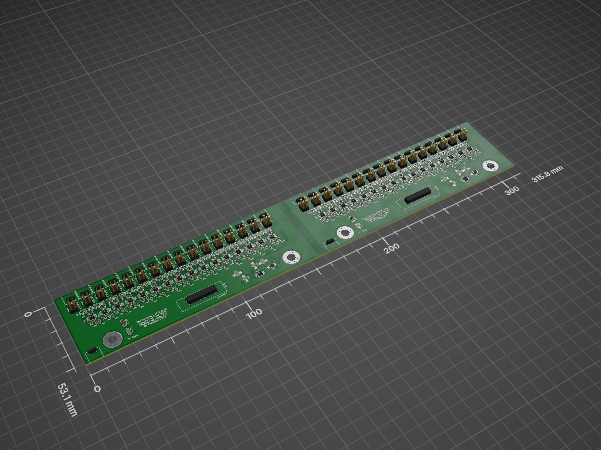
Thermoboard is an open-source printed circuit board by ParadigmHyperloop, from the ParadigmHyperloop/electrical repository on GitHub. It is a 2-layer board of 315.8 × 53.1 mm with 344 parts on 209 nets, routed with 2,127 tracks and 280 vias.
It is built around the AD849X and OPA380. Its parts include 132 capacitors, 104 resistors, 72 connectors, 34 ICs and 2 diodes.
BuildIn the most basic sense, this board is an Arduino with support for 2 modulated IR emitters and paired receivers. They are essentially smart IR proximity sensors.
These boards are intended to detect vertical strips (4" wide) that are placed every 100' on the hypertube walls. These strips are useful for navigation purposes and tell the pod where it is in the tube.
These boards are also somewhat of a prototype for a localized control module for subsystems like #brakes where a local uC receives commands from the main flight computer, but locally is the one responsible for controlling the state of the brake control solenoids, monitoring pressures and temperatures, etc.
There are 3 ports that all share the RS485 connection: 2x Ethernet jacks (for daisy chain), 1x 4 pin Phoenix contact port
This board is a 5V logic level board. The board may be powered over USB or via an external power source. The external power source is recommended at 5.5V. Do not exceed 12V on any of the external power inputs.
Power may be supplied through the 2 pin Phoenix Contact Power Connector as labeled on the board's silkscreen.
Alternatively, power may be supplied via the RJ45 jacks by supplying 5.5-12V on pin 8, and Ground on pin 7. The jumpers for VCOM power and VCOM GND must be stuffed in order to enable power via the Ethernet ports.
Do not plug these boards into a standard ethernet switch, behavior is undefined
5V Logic
VCC Regulated 5V
VCOM Recommended 5.5V

Ethernet Pinout:
1-2: RS485 RX - / +
3: External IR Sync
4-5: RS485 TX - / +
6: Passthrough
7: VCOM - (Ground)
8: VCOM + (5-12V DC)

VCOM PWR set jumpers
GND EN & VCOM EN | Qty | Value | Footprint | References |
|---|---|---|---|
| 96 | 0.1uF | Capacitors_SMD:C_0603_HandSoldering | C1001, C1002, C1004, C1101, C1102, C1104, C1201, C1202, C1204, C1301, C1302, C1304, C1401, C1402, C1404, C1501 +80 |
| 64 | 150 | Resistors_SMD:R_0603_HandSoldering | R1002, R1003, R1102, R1103, R1202, R1203, R1302, R1303, R1402, R1403, R1502, R1503, R1602, R1603, R1702, R1703 +48 |
| 34 | CONN_01X02 | thermoFootprints:phoenix_2pin_3.5mm | P101, P103, P105, P106, P107, P108, P109, P110, P111, P112, P113, P114, P115, P116, P117, P118 +18 |
| 32 | 1M | Resistors_SMD:R_0603_HandSoldering | R201, R1001, R1101, R1201, R1301, R1401, R1501, R1601, R1701, R1801, R1901, R2001, R2101, R2201, R2301, R2401 +16 |
| 32 | 1uF | Capacitors_SMD:C_0603_HandSoldering | C203, C1003, C1103, C1203, C1303, C1403, C1503, C1603, C1703, C1803, C1903, C2003, C2103, C2203, C2303, C2403 +16 |
| 32 | AD849X | Housings_SSOP:MSOP-8_3x3mm_Pitch0.65mm | U201, U1001, U1101, U1201, U1301, U1401, U1501, U1601, U1701, U1801, U1901, U2001, U2101, U2201, U2301, U2401 +16 |
| 32 | CONN_02X02 | Pin_Headers:Pin_Header_Straight_2x02_Pitch2.54mm | J101, J102, J103, J104, J105, J106, J107, J108, J109, J110, J111, J112, J113, J114, J115, J116 +16 |
| 4 | MOUNTING_HOLE | hyperCustom:MountingHole_5.5mm_Pad_Via | J133, J134, J135, J136 |
| 2 | 0 | Resistors_SMD:R_1206_HandSoldering | R103, R106 |
| 2 | 1k | Resistors_SMD:R_1206_HandSoldering | R102, R105 |
| 2 | 1uF | Capacitors_SMD:C_1206_HandSoldering | C101, C103 |
| 2 | 300 | SMD_Packages:SMD-1206_Pol | R107, R108 |
| 2 | 3k | Resistors_SMD:R_1206_HandSoldering | R101, R104 |
| 2 | CONN_02X08 | moboFootprints:302-S161 | P102, P104 |
| 2 | GREEN | LEDs:LED_1206 | D101, D102 |
| 2 | OPA380 | Housings_SSOP:MSOP-8_3x3mm_Pitch0.65mm | U101, U102 |
| 2 | SAT | Resistors_SMD:R_1206_HandSoldering | C102, C104 |
It measures 315.8 × 53.1 mm and has 2 copper layers, 1.6 mm thick.
344 parts, built around the AD849X and OPA380. The full list of its parts is on this page, with links to each part's symbol and footprint where PCBKit's library has them.
From the ParadigmHyperloop/electrical repository on GitHub, at the commit this page was made from: the board is THBO/Thermoboard.kicad_pcb. PCBKit opens the board in the browser, with nothing to install.
Its repository states no licence, so its author keeps all rights: ask ParadigmHyperloop before reusing the design.
ParadigmHyperloop/electrical
All schematics and layouts in KiCad, plus some simulations

ParadigmHyperloop/electrical
All schematics and layouts in KiCad, plus some simulations

ParadigmHyperloop/electrical
All schematics and layouts in KiCad, plus some simulations

ParadigmHyperloop/electrical
All schematics and layouts in KiCad, plus some simulations

ParadigmHyperloop/electrical
All schematics and layouts in KiCad, plus some simulations

ParadigmHyperloop/electrical
All schematics and layouts in KiCad, plus some simulations

ParadigmHyperloop/electrical
All schematics and layouts in KiCad, plus some simulations

ParadigmHyperloop/electrical
All schematics and layouts in KiCad, plus some simulations

ParadigmHyperloop/electrical
All schematics and layouts in KiCad, plus some simulations

ParadigmHyperloop/electrical
All schematics and layouts in KiCad, plus some simulations

ParadigmHyperloop/electrical
All schematics and layouts in KiCad, plus some simulations

ParadigmHyperloop/electrical
All schematics and layouts in KiCad, plus some simulations


SFUSatClub/xy-Panel
This repository uses the SFU Satellite Team's KiCad component library as a submodule. To start working on the repository:

SFUSatClub/z-panel
This repository uses the SFU Satellite Team's KiCad component library as a submodule. To start working on the repository:

jayis1/hacker-devices
Full-cycle hardware designs for security research devices — each device is a subfolder with its own README, schematics, PCB layout, and software stack


