
2 layers129 × 32 mm
Film capacitors
owntech-foundation/micro-inverter
A repository to do collective work on an open source micro-inverter.
20 parts118CERN-OHL-S-2.0

A repository to do collective work on an open source micro-inverter.
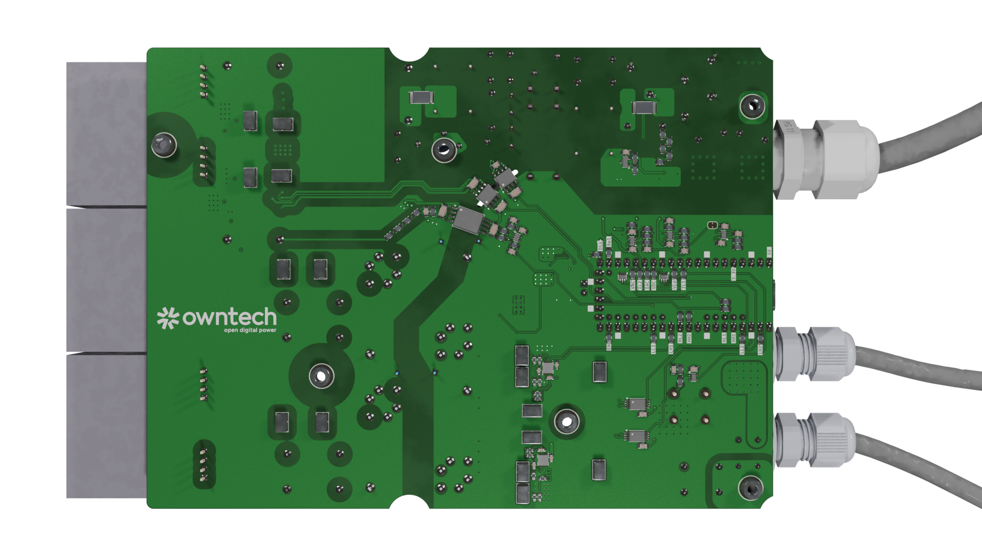
UVerter is an open-source printed circuit board by owntech-foundation, from the owntech-foundation/micro-inverter repository on GitHub, published under the CERN-OHL-S-2.0 licence. It is a 4-layer board of 178.9 × 131.8 mm with 402 parts on 226 nets, routed with 1,492 tracks and 529 vias.
It is built around the TL431, CJAC90SN12 and PMEG3010EH, with the 14D621K, TMOV14RP275E and ES1JW among its other parts. Its parts include 118 capacitors, 69 resistors, 14 ICs, 10 diodes and 10 transistors.


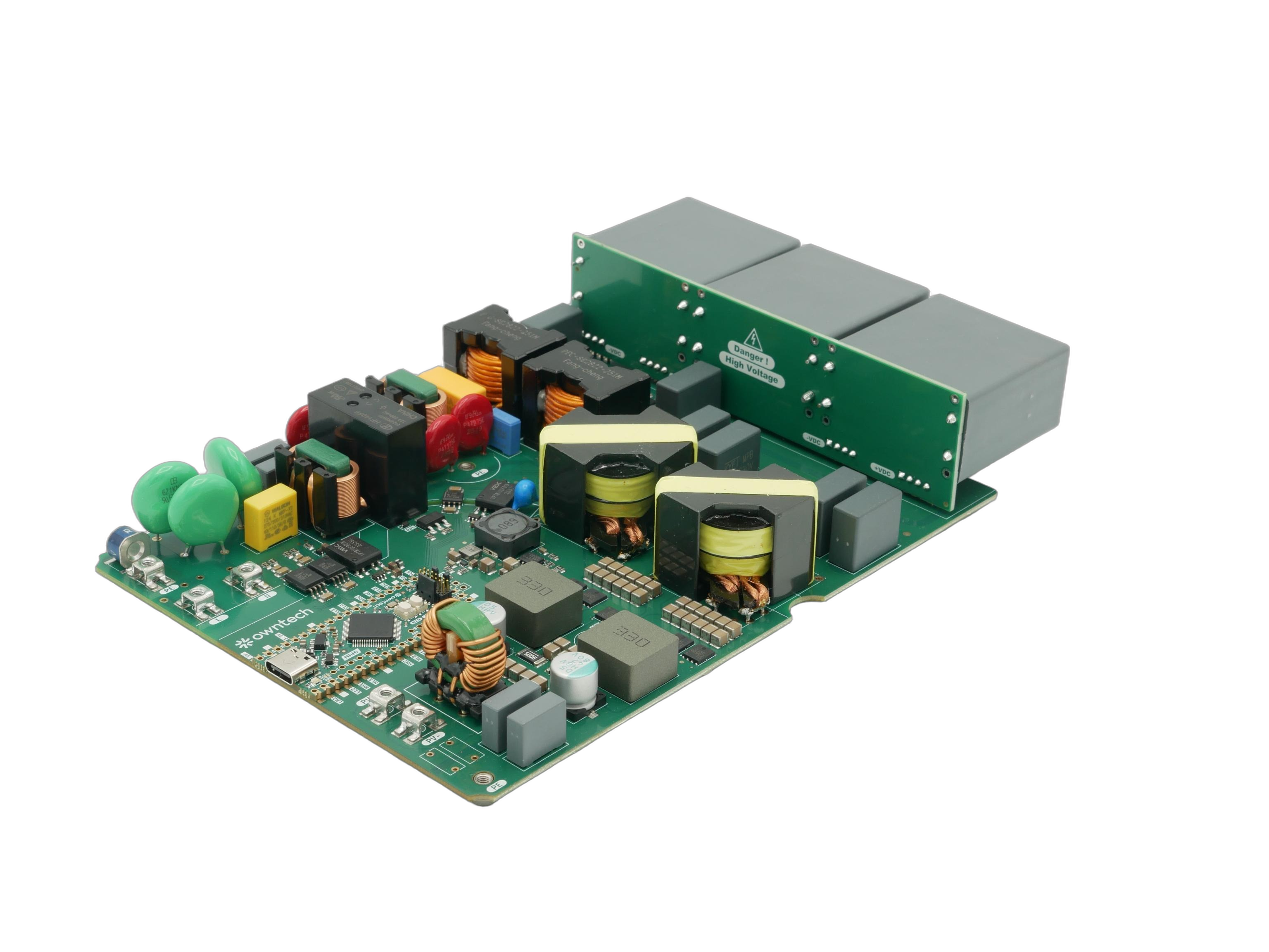
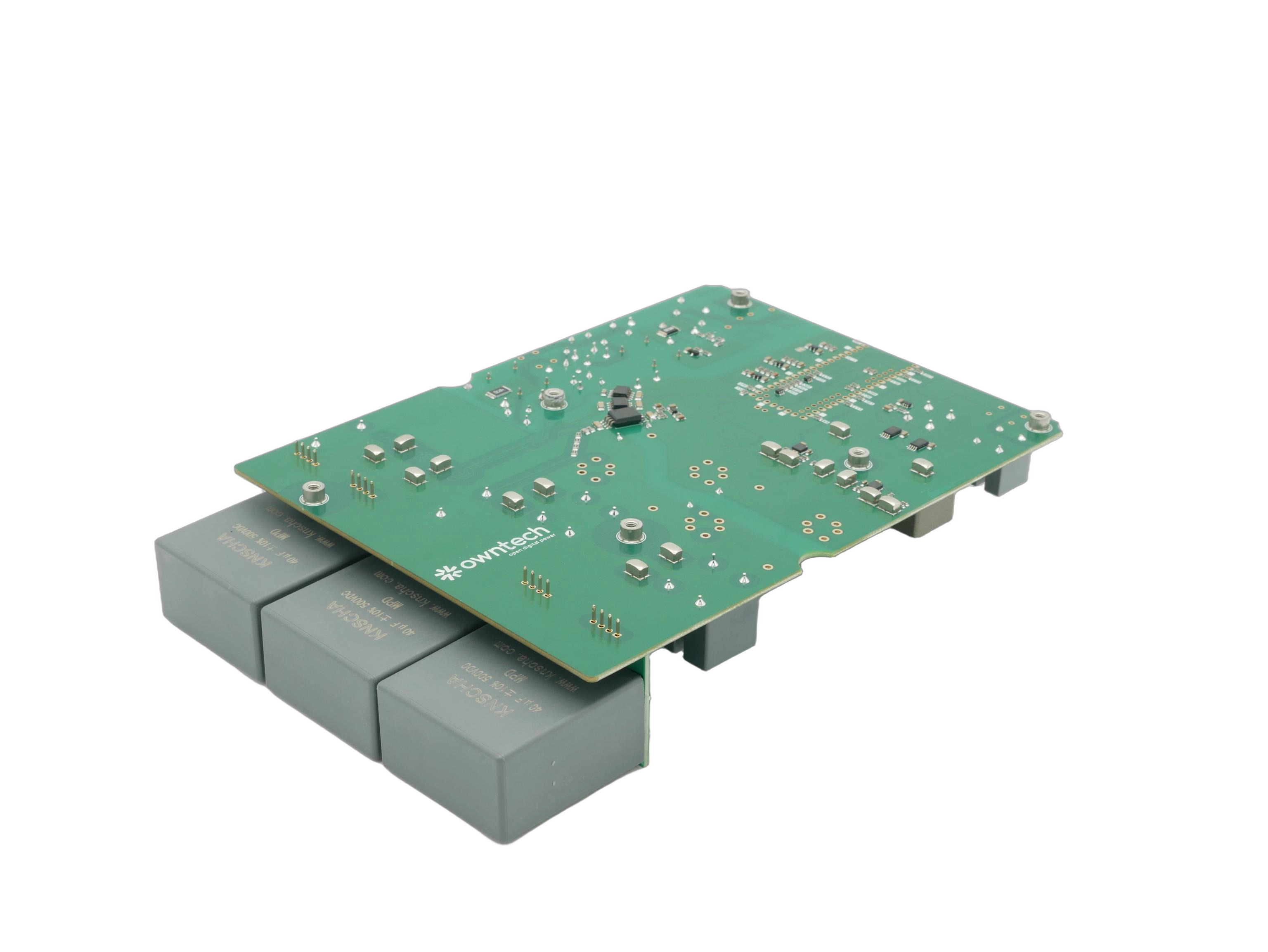
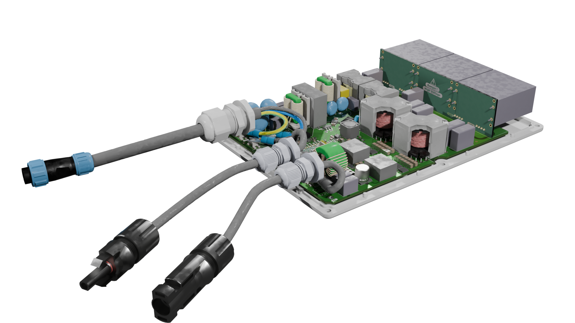
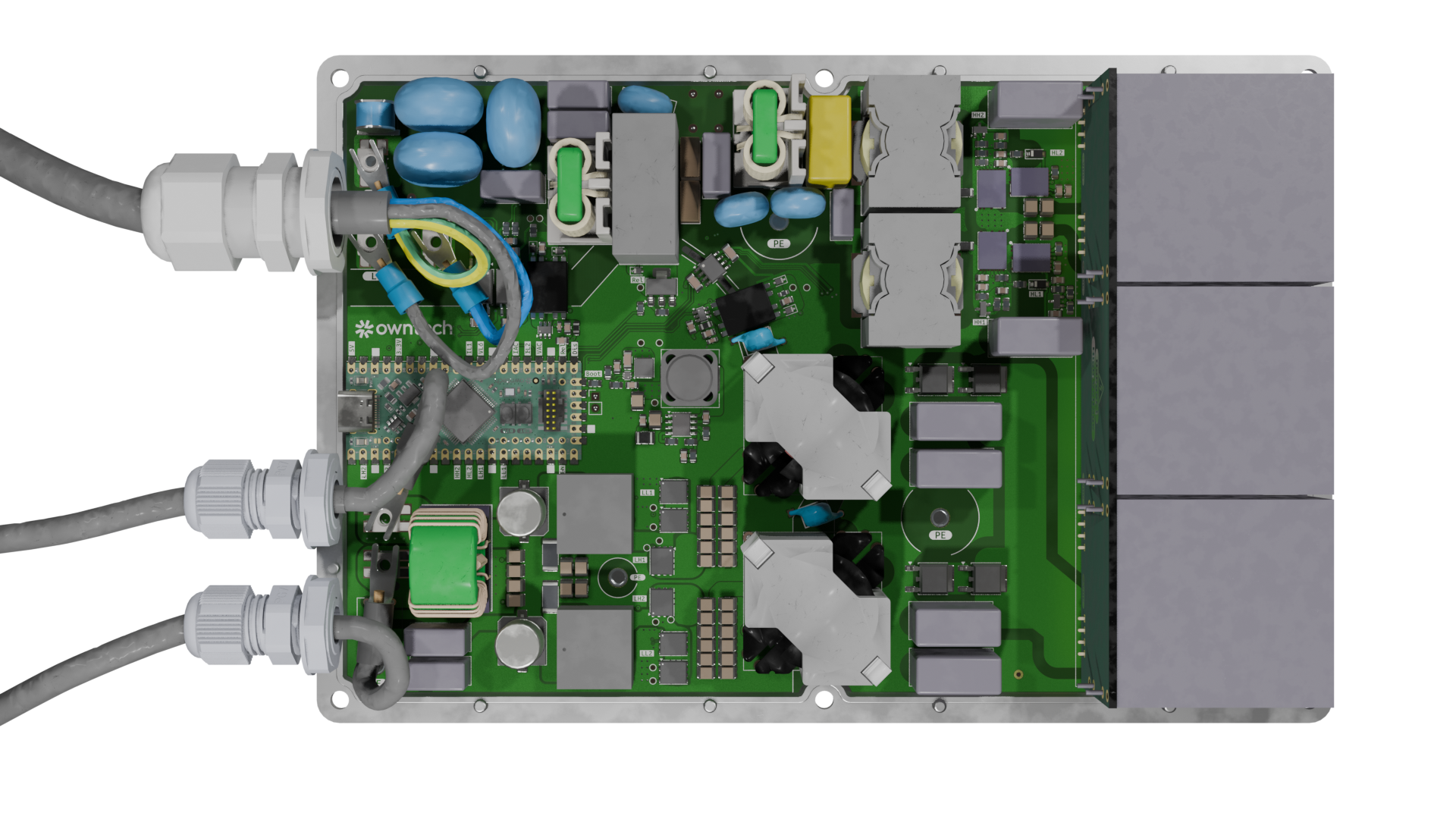
The project goal are :
In that sense, the owntech foundation aims at protecting this technical common.
This section is inspired from OpenMi
Comparison of micro-inverters with rated output power between 350VA and 400VA:
| Model | HM-350 | HM-400 | IQ7A | EVT300 | TSOL-M800 |
|---|---|---|---|---|---|
| Manufacturer | Hoymiles | Hoymiles | Enphase | Envertech | TSUN |
| Number of solar panels | 1 | 1 | 1 | 1 | 2 |
| Recommended input power (W) | 280-470+ | 320-540+ | 295-460 | 180-420+ | 2 $\cdot$ 280-440 |
| $V_{MPPT,min}$ (V) | 33 | 34 | 38 (18) | 24 | 33 |
| $V_{MPPT,max}$ (V) | 48 | 48 | 43 (58) | 45 | 48 |
| Start-up voltage (V) | 22 | 22 | 22 | - | - |
| Operating volage range (V) | 16-60 | 16-60 | 16-58 | 18-54 | 16-60 |
| Maximum input current (A) | 11.5 | 12 | 12 | 12 | 11.5 |
| Maximum input short circuit current (A) | 15 | 15 | 20 | 15 | 15 |
| Rated output power (VA) | 350 | 400 | 349 | 300 | 600 |
| Peak efficiency (%) | 96.7 | 96.7 | 97.7 | 95.4 | 96.7 |
| CEC weighted efficiency (%) | 96.5 | 96.5 | 97.0 | 95.0 | 96.5 |
| Category | Requirement | Notes |
|---|---|---|
| Grid | 220 V AC to 250V AC / 50 to 60 Hz | Hardware not compatible with 110V grids |
| Grid compliance | Grid-code compliant | Exact certification scope depends on country / standard |
| Rated apparent power | 450 VA | Software-limited power cap supported |
| Input DC operating range | 16 V – 58 V | PV module operating window |
| Recommended PV input power | 350 W – 550 W | Depends on module and thermal conditions |
| Efficiency | > 95% | Target at nominal conditions |
| Power factor | ≈ 1 | Near-unity PF at rated power |
| THD | < 5% | Total harmonic distortion at rated conditions |
| Isolation | Galvanic isolation | Electrical isolation between PV and grid |
| Operating temperature | -40 °C to +60 °C | Derating may apply |
| Repairability | No invasive potting | Designed to be serviceable / inspectable |
| Connectivity | Wi-Fi | Local-first monitoring (no proprietary cloud required) |
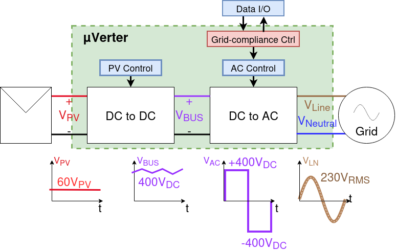
The control overview shows the uVerter as two coordinated stages: a PV-controlled DC/DC front end that regulates the panel operating point and raises the DC bus, followed by an AC control stage that shapes a grid-compliant AC output. Measurements and commands flow through Data I/O and the grid-compliance controller so the inverter can synchronize to line/neutral, limit harmonics, and maintain safe operation while power flows from the PV input to the grid.
The firmware/src/main.cpp file is the entry point for the uVerter firmware: it configures the sensors and power stages, sets up the real-time and background tasks, and runs the state machine plus control loops that drive the boost and inverter legs based on measurements and synchronization status.
loop_critical_task() at 100 µs to read sensors, enforce protections, regulate the boost stage, compute duty cycles, and update grid-sync variables.loop_application_task() to manage modes (idle/startup/power/error), handle transitions, and expose telemetry through the user data API.Micro-inverter uses PlatformIO as it's build and dependency management system.
Create and activate a Python virtual environment.
 python3 -m venv .owntech-venv
 source .owntech-venv/bin/activate
Install PlatformIO.
pip3 install platformioCompile the code. Dependencies (including Zephyr and Owntech libraries) are downloaded automatically.
 cd micro-inverter/firmware/
pio runfirmware directory via PlatformIO's home screen (not with VSCode's File -> Open)
⭐ Star this repository
Share the project with PV / power electronics / open-hardware communities
Mention it in meetups, forums, maker spaces, or your local energy co-op
Help us improve by opening GitHub issues:
Bug reports (schematic/PCB mistakes, BOM mismatches, mechanical interferences)
Documentation gaps (unclear steps, missing diagrams, confusing naming)
Feature requests
Start with Contribute.md — a living list of work items the community can pick up.
Whether you’re a student looking for a thesis topic, an engineer wanting to review a safety-critical design, or a maker growing skills in hardware and firmware: you’re welcome here.
Bring what you have: time, curiosity, test equipment, careful eyes, lived experience installing or repairing PV gear.
Let’s build an inverter that isn’t a black box — and keep it open, for everyone, forever.
This project is shared as-is, without any warranty of any kind, and without any guarantee of compliance with safety, EMC, or grid-connection regulations. By building, modifying, or using this design, you accept full responsibility for verification, testing, certification (if applicable), and safe operation.
Do not connect a prototype to the public grid. Grid connection must only happen after appropriate validation, protections, and (where required) third-party certification.
Building a micro-inverter is an advanced DIY project. It combines high energy, high voltage, fast switching, and grid interaction — a mix that can injure, start fires, or damage property
Key hazards include:
Electric shock and electrocution Internal stages can reach hundreds of volts. Multiple nets are high voltage. Some capacitors can stay charged after power-off. Treat the system as live until proven discharged and measured.
Fire and thermal runaway Faults can turn traces, connectors, inductors, or semiconductors into heaters in seconds. Thermal issues can escalate quickly.
We want this project to be open — not reckless. If you spot a safety issue (creepage/clearance, insulation, thermal margins, protection logic, connector ratings, etc.), please report it. Safety improvements are contributions that protect everyone.
EN IEC 62109-1:2010 Safety of power converters for use in photovoltaic power systems - Part 1: General requirements
EN IEC 62109-2:2011 Safety of power converters for use in photovoltaic power systems - Part 2: Particular requirements for inverters
EN 62920:2017+A11+A1:2021 Photovoltaic power generating systems - EMC requirements and test methods for power conversion equipment
ETSI EN 301 489-1 ElectroMagnetic Compatibility (EMC) standard for radio equipment and services; Part 1: Common technical requirements
ETSI EN 301 489-17 ElectroMagnetic Compatibility (EMC) standard for radio equipment and services; Part 17: Specific conditions for Broadband Data Transmission Systems
ETSI EN 300 328 V2.2.2 Wideband transmission systems; Data transmission equipment operating in the 2,4 GHz band; Harmonised Standard for access to radio spectrum
As grid regulations are country specific, please refer to Grid regulations
This project is licenced under CERN-OHL-V2-S open source hardware licence. Licence file can be found under License/cern-ohl-v2-s.
| Qty | Value | Footprint | References |
|---|---|---|---|
| 33 | 4.7uF | Footprints:C_1210_3225Metric | C103, C104, C105, C106, C107, C108, C109, C110, C128, C129, C130, C131, C132, C133, C134, C135 +17 |
| 16 | 5x3mm pad 3mm high | Footprints:Heatsink_BTC-533-ZN01 | HS3, HS4, HS5, HS9, HS10, HS11, HS12, HS101, HS104, HS105, HS106, HS107, HS108, HS109, HS110, HS111 |
| 14 | 100nF | Capacitor_SMD:C_0805_2012Metric | C28, C39, C44, C202, C405, C505, C702, C703, C707, C719, C804, C807, C808, C809 |
| 12 | TestPoint_Probe | Footprints:TestPoint_Pad_D1.0mm | TP102, TP104, TP106, TP108, TP109, TP701, TP702, TP703, TP704, TP705, TP706, TP707 |
| 11 | 100nF | Capacitor_SMD:C_1206_3216Metric | C42, C47, C402, C403, C502, C503, C801, C802, C803, C805, C806 |
| 11 | 120R | Footprints:R_0805_2012Metric | R908, R909, R910, R911, R912, R913, R914, R915, R916, R917, R918 |
| 10 | 10k | Footprints:R_0805_2012Metric | R14, R15, R401, R402, R403, R404, R501, R502, R702, R706 |
| 9 | 10k | Resistor_SMD:R_0805_2012Metric | R13, R710, R711, R801, R802, R805, R806, R808, R809 |
| 7 | 10uF | Capacitor_SMD:C_0805_2012Metric | C706, C709, C710, C711, C712, C715, C716 |
| 6 | 1uF | Capacitor_THT:C_Rect_L18.0mm_W8.0mm_P15.00mm_FKS3_FKP3 | C22, C27, C33, C38, C121, C127 |
| 6 | 560R | Footprints:R_0805_2012Metric | R902, R903, R904, R905, R906, R907 |
| 6 | CJAC90SN12 | Footprints:DFN-8-1EP_5x6_P1.27mm | Q5, Q6, Q7, Q8, Q9, Q10 |
| 6 | M3x3.5 | Footprints:MountingHole_Pad_SMD_BD5.6-D4.1 | H1, H2, H3, H4, H5, H6 |
| 5 | 20 | Resistor_SMD:R_0603_1608Metric | R104, R105, R106, R107, R108 |
| 5 | 20k | Resistor_SMD:R_0603_1608Metric | R8, R32, R33, R101, R109 |
| 5 | Conn_01x01 | Footprints:Connector_SMD-4_TS34056055-0440 | J1, J2, J3, J5, J8 |
| 5 | G*** | kibuzzard-696E53C3 | kibuzzard-696E53C3, kibuzzard-696E53C3, kibuzzard-696E53C3, kibuzzard-696E53C3, kibuzzard-696E53C3 |
| 5 | MCP6486UT-E/LT | Package_TO_SOT_SMD:SOT-353_SC-70-5 | U8, U201, U402, U502, U701 |
| 4 | 1.13M | Resistor_SMD:R_0805_2012Metric | Rv401, Rv402, Rv403, Rv404 |
| 4 | 100nF | Capacitor_SMD:C_1210_3225Metric | C16, C17, C114, C115 |
| 4 | 10R | Resistor_SMD:R_0805_2012Metric | Rv15, Rv16, Rv506, Rv507 |
| 4 | 1uF | Capacitor_SMD:C_0805_2012Metric | C1, C3, C12, C14 |
| 4 | 33 | Resistor_SMD:R_0805_2012Metric | R1, R2, R4, R5 |
| 4 | 332k | Resistor_SMD:R_0805_2012Metric | Rv501, Rv502, Rv503, Rv504 |
| 4 | 4.7nF | Capacitor_THT:C_Rect_L13.0mm_W6.0mm_P10.00mm_FKS3_FKP3_MKS4 | C5, C10, C116, C117 |
| 4 | 4.7uF | Capacitor_SMD:C_0805_2012Metric | C13, C15, C101, C102 |
| 4 | 470nF | Capacitor_SMD:C_0603_1608Metric | C8, C9, C40, C53 |
| 4 | 470pF | Footprints:C_0805_2012Metric | C204, C205, C301, C404 |
| 4 | CID12N65D | Footprints:DFN-10_L8.0-W6.0_CID12N65D | Q1, Q2, Q3, Q4 |
| 4 | D_Schottky | Footprints:TO-252-2_Diode | D1, D2, D3, D4 |
| 4 | PMEG3010 | Diode_SMD:D_SOD-323F | D701, D702, D703, D704 |
| 4 | TL431 | Package_TO_SOT_SMD:SOT-23 | U705, U804, U805, U806 |
| 4 | TestPoint_Probe | Footprints:TestPoint_Pad_D0.5mm | TP101, TP103, TP105, TP107 |
| 3 | 12.1k | Footprints:R_0805_2012Metric | R16, R17, R202 |
| 3 | 14D621 | Footprints:RV_Disc_D15.5mm_W11mm_P7.5mm | RV1, RV2, RV3 |
| 3 | 1nF | Capacitor_THT:C_Rect_L10.3mm_W4.5mm_P7.50mm_MKS4 | C120, C125, C126 |
| 3 | Fiducial | Fiducial:Fiducial_1mm_Mask2mm | FID1, FID2, FID3 |
| 3 | G*** | kibuzzard-6973D002 | kibuzzard-6973D002, kibuzzard-6973D002, kibuzzard-6973D002 |
| 3 | G*** | kibuzzard-6973D0DA | kibuzzard-6973D0DA, kibuzzard-6973D0DA, kibuzzard-6973D0DA |
| 3 | ISO7720FDR | Package_SO:SOIC-8_3.9x4.9mm_P1.27mm | U801, U802, U803 |
| 3 | TMOV14RP275 | Varistor:RV_Disc_D12mm_W6.2mm_P7.5mm | RV101, RV102, RV103 |
| 2 | 100nF | Capacitor_SMD:C_0603_1608Metric | C713, C714 |
| 2 | 10k | Resistor_SMD:R_0603_1608Metric | R9, R110 |
| 2 | 10nF | Footprints:C_0805_2012Metric | C46, C501 |
| 2 | 10uH | Inductor_SMD:L_0805_2012Metric | L703, L704 |
| 2 | 110k | Footprints:R_0805_2012Metric | R701, R704 |
| 2 | 120nF | Capacitor_THT:C_Rect_L13.0mm_W6.0mm_P10.00mm_FKS3_FKP3_MKS4 | C113, C122 |
| 2 | 1k | Resistor_SMD:R_0805_2012Metric | R803, R804 |
| 2 | 1nF | Capacitor_SMD:C_0603_1608Metric | C136, C137 |
| 2 | 1nF | Footprints:C_TH_L6.3-W4.4-P10.00-D0.6-S3.8 | C118, C119 |
| 2 | 1nF | Footprints:C_0805_2012Metric | C406, C407 |
| 2 | 2.2nF | Capacitor_THT:C_Rect_L10.3mm_W4.5mm_P7.50mm_MKS4 | C123, C124 |
| 2 | 2.2nF | Capacitor_THT:C_Rect_L9.0mm_W4.0mm_P7.50mm_MKT | C11, C54 |
| 2 | 2.5A | Footprints:FUSE-TH_L8.4-W4.1-P5.08-D0.6 | F1, F101 |
| 2 | 20pF | Footprints:C_0805_2012Metric | C201, C203 |
| 2 | 250uH | Footprints:L_SMD_L28.0-W23-LS25 | L1, L3 |
| 2 | 3.3R | Resistor_SMD:R_0805_2012Metric | R102, R103 |
| 2 | 300@100MHz | Inductor_SMD:L_1206_3216Metric | FB1, FB2 |
| 2 | 33uH | Footprints:L_SRP1510CA-330M | L5, L6 |
| 2 | 4.87k | Footprints:R_0805_2012Metric | R503, R504 |
| 2 | 47R | Resistor_SMD:R_0805_2012Metric | R12, R709 |
| 2 | 47k | Footprints:R_0805_2012Metric | R201, R901 |
| 2 | 47uF | Capacitor_SMD:C_Elec_10x10.2 | C111, C112 |
| 2 | 5mH | Footprints:Choke_TH_XRSQ1515-5MH-V-1013 | FL1, FL2 |
| 2 | 5mR | Resistor_SMD:R_2512_6332Metric | R7, R10 |
| 2 | AMC1301DWR | Package_SO:SOIC-8_7.5x5.85mm_P1.27mm | U5, U501 |
| 2 | ES1JW | Footprints:D_SOD-123 | D101, D102 |
| 2 | G*** | kibuzzard-6973CFDB | kibuzzard-6973CFDB, kibuzzard-6973CFDB |
| 2 | G*** | kibuzzard-6973CFBE | kibuzzard-6973CFBE, kibuzzard-6973CFBE |
| 2 | G*** | kibuzzard-6973D0E6 | kibuzzard-6973D0E6, kibuzzard-6973D0E6 |
| 2 | G*** | kibuzzard-6973D01A | kibuzzard-6973D01A, kibuzzard-6973D01A |
| 2 | G*** | kibuzzard-6973D084 | kibuzzard-6973D084, kibuzzard-6973D084 |
| 2 | G*** | kibuzzard-6973D0F4 | kibuzzard-6973D0F4, kibuzzard-6973D0F4 |
| 2 | G*** | kibuzzard-6973D0CE | kibuzzard-6973D0CE, kibuzzard-6973D0CE |
| 2 | G*** | kibuzzard-6973CF69 | kibuzzard-6973CF69, kibuzzard-6973CF69 |
| 2 | G*** | kibuzzard-6973D19D | kibuzzard-6973D19D, kibuzzard-6973D19D |
| 2 | G*** | kibuzzard-6973CFAE | kibuzzard-6973CFAE, kibuzzard-6973CFAE |
| 2 | G*** | kibuzzard-6973D09F | kibuzzard-6973D09F, kibuzzard-6973D09F |
| 2 | G*** | kibuzzard-6973D1AD | kibuzzard-6973D1AD, kibuzzard-6973D1AD |
| 2 | G*** | kibuzzard-6973D0B4 | kibuzzard-6973D0B4, kibuzzard-6973D0B4 |
The 334 most common of 402 parts.
owntech-foundation/micro-inverter
A repository to do collective work on an open source micro-inverter.

cirBATT/cirbattverter
cirBATT open hardware 48 V to 230 V battery inverter: KiCad power electronics, EGS005Q control and second-life lithium battery integration. Prototype under review.

hicancan/carbentra-smart-switch
CARBENTRA three-channel smart switch: hardware, firmware and local engineering checks


kcuzner/rt-soldering-iron
Soldering iron driver board for Weller RT tips. A work in progress. Firmware in rust.
It measures 178.9 × 131.8 mm and has 4 copper layers, 1.6 mm thick.
402 parts, built around the TL431, CJAC90SN12, PMEG3010EH and 14D621K. The full list of its parts is on this page, with links to each part's symbol and footprint where PCBKit's library has them.
From the owntech-foundation/micro-inverter repository on GitHub, at the commit this page was made from: the board is KiCAD_Files/uVerter.kicad_pcb and its schematic KiCAD_Files/AC_voltage_sense.kicad_sch. PCBKit opens the board in the browser, with nothing to install.
Its repository publishes it under the CERN-OHL-S-2.0 licence: you may reuse it on that licence's terms (keep the author's notice, and for a copyleft licence share your changes alike).