

2 layers23.2 × 50.6 mm

 open-batt/openbms-test-bench-hardware2
OpenBMS 600W resistive load (dissipative) hardware [schematic] [PCB layout]
Openbms load is an open-source printed circuit board by open-batt, from the open-batt/openbms-test-bench-hardware repository on GitHub, published under the MIT licence. It is a 2-layer board of 327.5 × 219.5 mm with 113 parts on 45 nets, routed with 252 tracks and 13 vias.
It is built around the LMZM23600SILR. Its parts include 29 connectors, 21 fuses, 20 resistors, 6 capacitors and 4 diodes. It belongs with the power boards of this library.

OpenBMS Test Bench is a hardware design of a resistive load used for battery discharging. Its main purpose is testing the battery management system (BMS) during charge and discharge cycles.
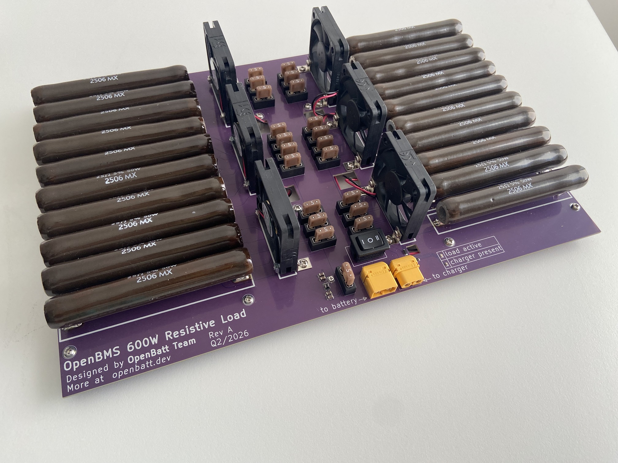
Battery system consists of:
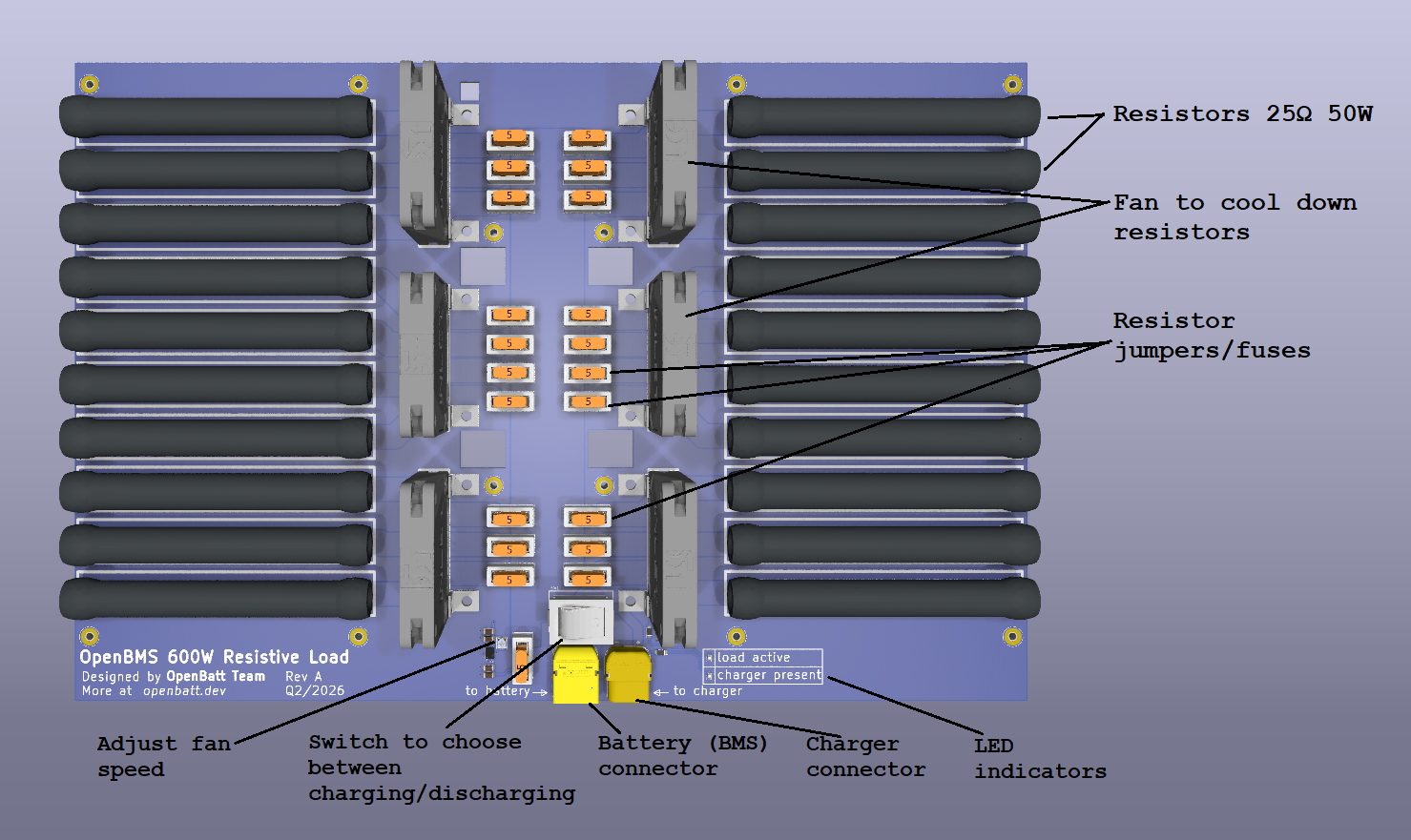
The OpenBMS Test Bench, a 600W resistive load, is a purpose-built battery testing board designed to work alongside the OpenBMS system.
It carries twenty 25Ω 50W wirewound resistors arranged across the board, capable of dissipating up to 600W of power. Each resistor is individually switchable via a jumper and protected by a 5A fuse, allowing the total load resistance to be adjusted between 1 and 20 ohms.
Six cooling fans keep the resistors from overheating, with speed controlled by an onboard potentiometer.
Two XT60 connectors handle battery and charger connections, and a three-position switch selects between discharging (energy flows from battery into the resistors), charging (charger feeds the battery directly, bypassing the resistors), and idle mode.
A green LED signals charger presence and a red LED indicates active discharging.
This project is funded through NGI0 Commons Fund, a fund established by NLnet with financial support from the European Commission's Next Generation Internet program.


We are very grateful to the NLnet team for helping us on our path, and we encourage you too to apply and get funds to build your project! 🚀 Learn more at the NLnet project page.
OpenBMS Test Bench is licensed under CERN OHL-S v2 license.
Check openbatt.dev for more!
| Qty | Value | Footprint | References |
|---|---|---|---|
| 21 | 5A Fuse | custom_library:0297005.WXNV | J1, J2, J3, J4, J10, J11, J12, J13, J14, J15, J16, J17, J18, J19, J20, J21 +5 |
| 21 | Fuse housing | custom_library:3568 | F1, F2, F3, F4, F10, F11, F12, F13, F14, F15, F16, F17, F18, F19, F20, F21 +5 |
| 20 | 25R 50W | custom_library:L50J25RE | R1, R2, R3, R4, R5, R10, R11, R12, R13, R14, R15, R16, R17, R18, R19, R20 +4 |
| 12 | L mounting bracket | custom_library:633 | B1, B2, B3, B4, B5, B6, B7, B8, B9, B10, B11, B12 |
| 12 | Standoff M3 10mm | custom_library:24433 | H1, H2, H3, H4, H5, H6, H7, H8, H9, H10, H11, H12 |
| 6 | Fan 50mm | custom_library:fan_MF50101V1-1000U-A99 | M1, M2, M3, M4, M5, M6 |
| 6 | JST connector | custom_library:JST_PH_S2B-PH-SM4-TB_1x02-1MP_P2.00mm_Horizontal | P1, P2, P3, P4, P5, P6 |
| 4 | 10u | Capacitor_SMD:C_1206_3216Metric | C1, C2, C4, C5 |
| 2 | 100n | Capacitor_SMD:C_0402_1005Metric | C3, C6 |
| 2 | LED driver | custom_library:AL5809-15P1-7 | D3, D4 |
| 1 | 10k pot | custom_library:TC33X2503E | POT1 |
| 1 | Green LED | LED_SMD:LED_0603_1608Metric | D1 |
| 1 | LMZM23600SILR | custom_library:LMZM23600SILR | U1 |
| 1 | Red LED | LED_SMD:LED_0603_1608Metric | D2 |
| 1 | Switch | custom_library:VRS-3-Q3PSI-19KNN-0-M2 | SW1 |
| 1 | XT60PW-F connector | custom_library:AMASS_XT60PW-F_1x02_P7.20mm_Horizontal | P8 |
| 1 | XT60PW-M connector | custom_library:AMASS_XT60PW-M_1x02_P7.20mm_Horizontal | P7 |

alu-source/open_USAN
This project documents the software and hardware of an ultrasonic anemometer, created in cooperation between FH Aachen and DLR Göttingen


hirakuni45/RX
Renesas RX Microcontroller, C++ framework, Library, Sample
It measures 327.5 × 219.5 mm and has 2 copper layers, 1.6 mm thick.
113 parts, built around the LMZM23600SILR. The full list of its parts is on this page, with links to each part's symbol and footprint where PCBKit's library has them.
From the open-batt/openbms-test-bench-hardware repository on GitHub, at the commit this page was made from: the board is openbms-load/openbms-load.kicad_pcb and its schematic openbms-load/connectors.kicad_sch. PCBKit opens the board in the browser, with nothing to install.
Its repository publishes it under the MIT licence: you may reuse it on that licence's terms (keep the author's notice, and for a copyleft licence share your changes alike).