

2 layers62 × 98 mm
Stepper driver
Open-2-Photon-Microscope/3-axis-controller
a controller system to operate motors and microscope XYZ stage
17 parts

 Open-2-Photon-Microscope/3-axis-controller
a controller system to operate motors and microscope XYZ stage
Integrated board is an open-source printed circuit board by Open-2-Photon-Microscope, from the Open-2-Photon-Microscope/3-axis-controller repository on GitHub. It is a 2-layer board of 98.5 × 111 mm with 69 parts on 82 nets, routed with 374 tracks and 1 via.
It is built around the LM2596T-5.0 and ULN2003. Its parts include 23 resistors, 20 connectors, 15 capacitors, 4 ICs and 2 diodes. It belongs with the ESP32 boards of this library.
A manipulator device to operate microscope stage XYZ translations. This project was specifically designed for the OpenFlexure Delta Stage.
view > files) navigate to the location of the code to be installedlibUpload to /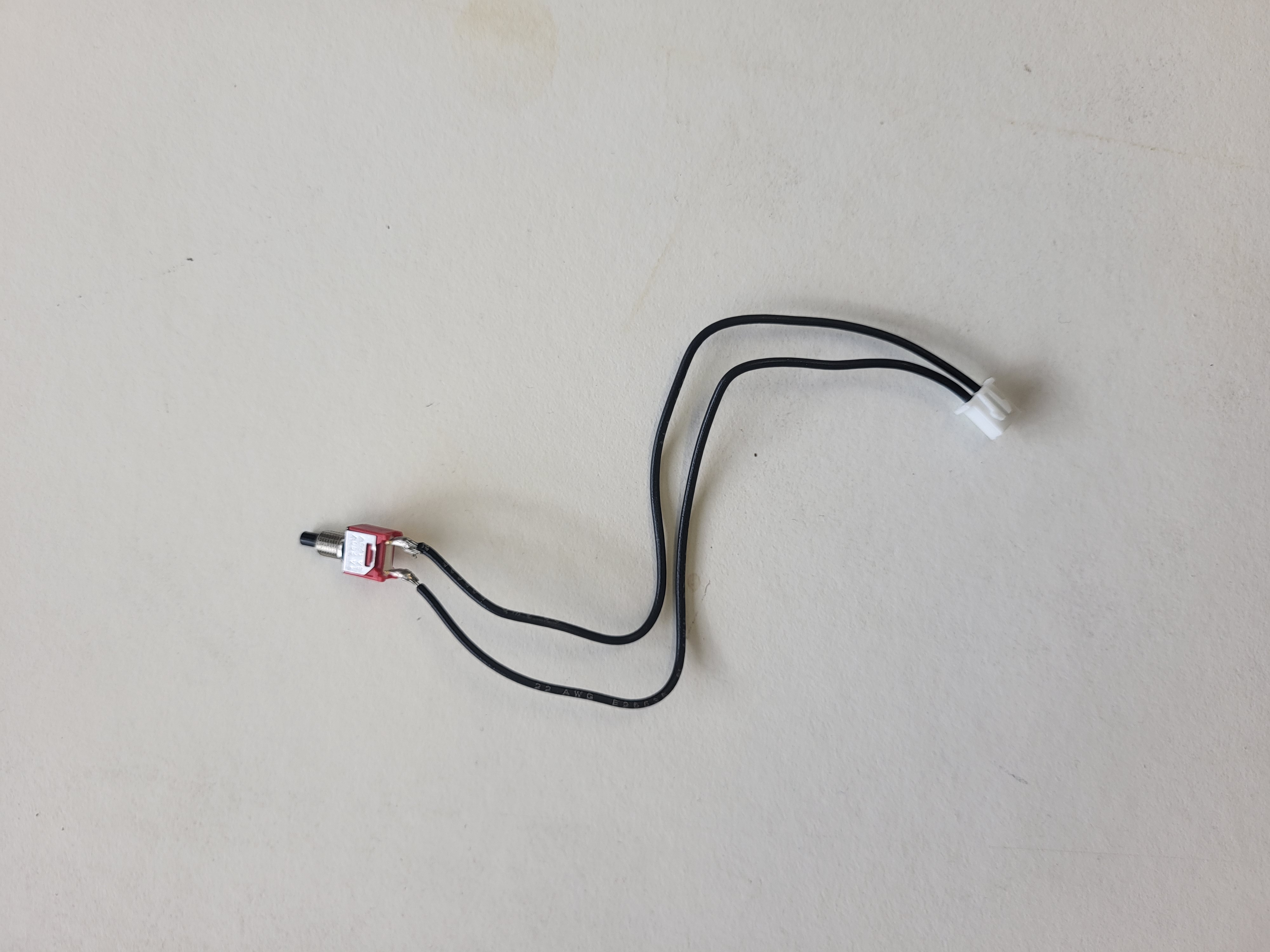
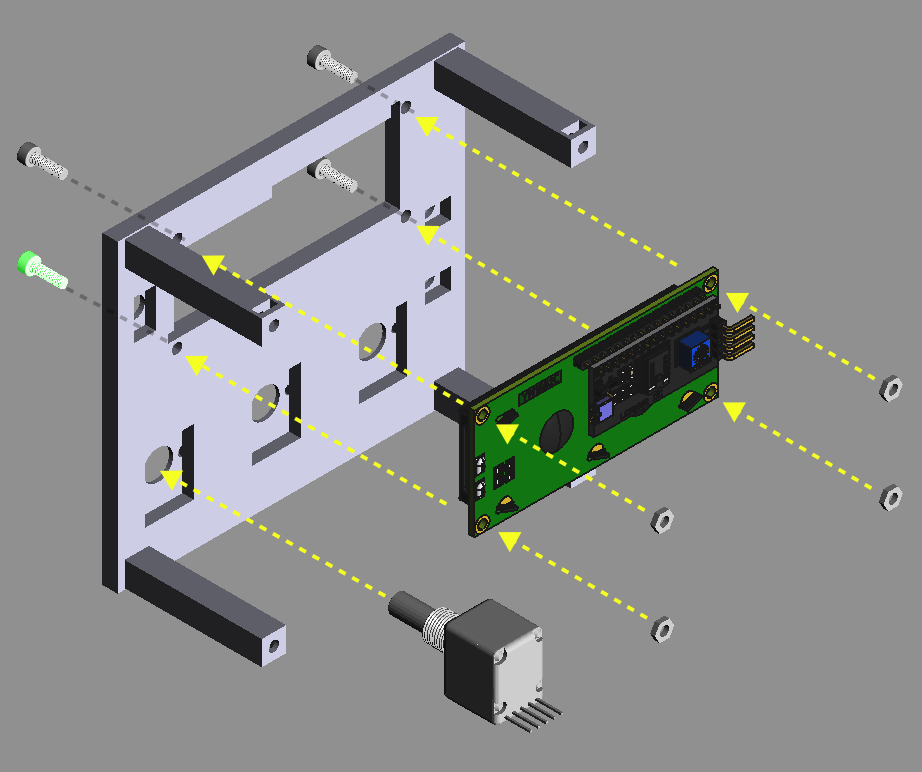
Note you should have all components wired up and screwed in at this point, not all of this is shown on the diagram.
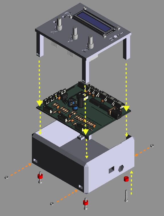
lib portion of the I2C code another way - the above method should work, so only follow these instructions if something is not behaving as expected.Tools > Manage Packages
.tar.gz file you downloaded| Qty | Value | Footprint | References |
|---|---|---|---|
| 12 | 1kΩ | Resistor_THT:R_Axial_DIN0309_L9.0mm_D3.2mm_P12.70mm_Horizontal | R1, R2, R4, R5, R10, R11, R13, R14, R22, R23, R25, R26 |
| 6 | 1.8k | Resistor_THT:R_Axial_DIN0309_L9.0mm_D3.2mm_P12.70mm_Horizontal | R3, R6, R12, R15, R24, R27 |
| 6 | 22nF | Capacitor_THT:C_Disc_D6.0mm_W4.4mm_P5.00mm | C1, C2, C8, C9, C10, C11 |
| 5 | 33nF | Capacitor_THT:C_Disc_D6.0mm_W4.4mm_P5.00mm | C7, C12, C13, C14, C15 |
| 4 | MountingHole | MountingHole:MountingHole_3.2mm_M3_DIN965 | H1, H2, H3, H4 |
| 2 | 10µF | Capacitor_THT:C_Disc_D6.0mm_W4.4mm_P5.00mm | C3, C4 |
| 2 | Conn_01x16 | Connector_PinHeader_2.54mm:PinHeader_1x10_P2.54mm_Vertical | J8, J9 |
| 2 | Conn_Coaxial | Connector_Coaxial:BNC_Amphenol_B6252HB-NPP3G-50_Horizontal | J1, J2 |
| 2 | ULN2003 | Package_DIP:DIP-16_W7.62mm_LongPads | U1, U2 |
| 1 | 1.8K | Resistor_THT:R_Axial_DIN0309_L9.0mm_D3.2mm_P12.70mm_Horizontal | R17 |
| 1 | 100K | Resistor_THT:R_Axial_DIN0309_L9.0mm_D3.2mm_P12.70mm_Horizontal | R8 |
| 1 | 100k | Resistor_THT:R_Axial_DIN0309_L9.0mm_D3.2mm_P12.70mm_Horizontal | R9 |
| 1 | 1K | Resistor_THT:R_Axial_DIN0309_L9.0mm_D3.2mm_P12.70mm_Horizontal | R16 |
| 1 | 220µ | Capacitor_THT:CP_Radial_D8.0mm_P3.80mm | C6 |
| 1 | 33µH | Inductor_THT:L_Radial_D10.0mm_P5.00mm_Neosid_SD12_style3 | L1 |
| 1 | 560 | Resistor_THT:R_Box_L13.0mm_W4.0mm_P9.00mm | R7 |
| 1 | 680µ | Capacitor_THT:CP_Radial_D10.0mm_P2.50mm_P5.00mm | C5 |
| 1 | BARREL_JACK | Connector_BarrelJack:BarrelJack_Horizontal | CON1 |
| 1 | Conn_01x02 | Connector_JST:JST_XH_B2B-XH-A_1x02_P2.50mm_Vertical | P1 |
| 1 | ESP32-DEVKITC-32D | footprints:MODULE_ESP32-DEVKITC-32D | U4 |
| 1 | Endstop A | Connector_JST:JST_XH_S2B-XH-A_1x02_P2.50mm_Horizontal | J5 |
| 1 | Endstop B | Connector_JST:JST_XH_S2B-XH-A_1x02_P2.50mm_Horizontal | J6 |
| 1 | Endstop C | Connector_JST:JST_XH_S2B-XH-A_1x02_P2.50mm_Horizontal | J7 |
| 1 | LCD | Connector_JST:JST_XH_B4B-XH-A_1x04_P2.50mm_Vertical | P2 |
| 1 | LED | LED_THT:LED_D3.0mm | D2 |
| 1 | LM2596T-5 | Package_TO_SOT_THT:TO-220-5_P3.4x3.7mm_StaggerOdd_Lead3.8mm_Vertical | U3 |
| 1 | Schottky 5A | Diode_THT:D_DO-201AD_P15.24mm_Horizontal | D1 |
| 1 | Switch 1 | Connector_JST:JST_XH_B2B-XH-A_1x02_P2.50mm_Vertical | J11 |
| 1 | Switch 2 | Connector_JST:JST_XH_B2B-XH-A_1x02_P2.50mm_Vertical | J4 |
| 1 | UART | Connector_JST:JST_XH_B4B-XH-A_1x04_P2.50mm_Vertical | P16 |
| 1 | motor1(15,2,0,4) | Connector_JST:JST_XH_S5B-XH-A_1x05_P2.50mm_Horizontal | J13 |
| 1 | motor2 (16,17,5,18) | Connector_JST:JST_XH_S5B-XH-A_1x05_P2.50mm_Horizontal | J15 |
| 1 | motor3 (19,21,22,23) | Connector_JST:JST_XH_S5B-XH-A_1x05_P2.50mm_Horizontal | J17 |
| 1 | pcf8575 IO expander | Connector_PinHeader_2.54mm:PinHeader_1x05_P2.54mm_Vertical | J10 |
| 1 | rot_encoderX(14,27) | Connector_JST:JST_XH_B5B-XH-A_1x05_P2.50mm_Vertical | J12 |
| 1 | rot_encoderY(25,26) | Connector_JST:JST_XH_B5B-XH-A_1x05_P2.50mm_Vertical | J14 |
| 1 | rot_encoderZ(35,34) | Connector_JST:JST_XH_B5B-XH-A_1x05_P2.50mm_Vertical | J16 |
It measures 98.5 × 111 mm and has 2 copper layers, 1.6 mm thick.
69 parts, built around the LM2596T-5.0 and ULN2003. The full list of its parts is on this page, with links to each part's symbol and footprint where PCBKit's library has them.
From the Open-2-Photon-Microscope/3-axis-controller repository on GitHub, at the commit this page was made from: the board is electronics/integrated_board/integrated_board.kicad_pcb and its schematic electronics/GPIO_expander_board/GPIO_expander_board.kicad_sch. PCBKit opens the board in the browser, with nothing to install.
Its repository states no licence, so its author keeps all rights: ask Open-2-Photon-Microscope before reusing the design.
Open-2-Photon-Microscope/3-axis-controller
a controller system to operate motors and microscope XYZ stage

Open-2-Photon-Microscope/3-axis-controller
a controller system to operate motors and microscope XYZ stage

Open-2-Photon-Microscope/3-axis-controller
a controller system to operate motors and microscope XYZ stage


AidanHockey5/STM32_VGM_Player_YM2612_SN76489
A Sega Genesis music player based off of the STM32 BluePill board and real YM2612+SN76489 sound chips.


anujthakur512/Buck-Converter-5V
I build a Buck Converter (5V) using IC LM2596 on KiCad as my 1st project of learning PCB Designing.

BadenLab/Open-Visual-Stimulator
An arbitrary-spectrum spatial visual stimulator for vision research

jrtaylor71/Smart-Thermostat-Alt-Firmware
A comprehensive, feature-rich smart thermostat firmware for ESP32-S3 microcontrollers with touch display, web interface, and Home Assistant integration.

alexsomesan/nmea0183-i2c-wifi
Reads wind data from a NASA Clipper wind instrument via I2C and sends out NMEA0183 wind messages via WiFi.