Skip to the content
PCBKitNew board
2 layers62 × 98 mmStepper driver, the printed circuit board in 3D

a controller system to operate motors and microscope XYZ stage

Size
62 × 98 mm
Copper layers
2
Thickness
1.6 mm
Parts
17
Nets
30
Pads
79
Tracks, vias
106, 0
Pours
1
Routed
Yes
KiCad
KiCad 6 (file 20211014)
Created
16 Jun 2022
Updated
30 Sep 2025

Overview

Stepper driver is an open-source printed circuit board by Open-2-Photon-Microscope, from the Open-2-Photon-Microscope/3-axis-controller repository on GitHub. It is a 2-layer board of 62 × 98 mm with 17 parts on 30 nets, routed with 106 tracks and 0 vias.

It is built around the ULN2003. Its parts include 9 connectors, 2 capacitors and 2 ICs. It belongs with the robots and motor control boards of this library.

Main components

1

README

README.md

3-axis-controller

A manipulator device to operate microscope stage XYZ translations. This project was specifically designed for the OpenFlexure Delta Stage.

Assembly

Assembling the Board

  1. Order the (2 layer) board from a PCB manufacturer (e.g. JLCPCB) by uploading this file.
  2. Using the BOM, solder together the integrated board from electronics/integrated_board. The board is labeled with the locations and values of resistors, capacitors etc.
    • Make sure to solder socket headers to the board and slot in the esp32 and pcf8575 modules rather than soldering them directly to the board. Sometimes things go wrong and they will be very hard to remove...
    • All parts are intended to be soldered as sitting on the top face of the board - any differences seen in the 3D view of the PCB in KiCAD should be ignored

Software

Setting up MicroPython with Thonny IDE

  1. Follow the tutorial on this page if you haven't already done so when assembling the board.

Upload the Code

  1. Download the code here
  2. Open them all in Thonny.
    • Connect your board to your PC via micro USB.
  3. In Thonny, in the files panel (view > files) navigate to the location of the code to be installed
  4. Highlight all files and folders, including lib
  5. Right click and select Upload to /
  6. CHECK: Does the file layout in the esp32 look like that on this GitHub?

Assembling the controller

  1. Assemble the JST-XH cables mentioned in the BOM
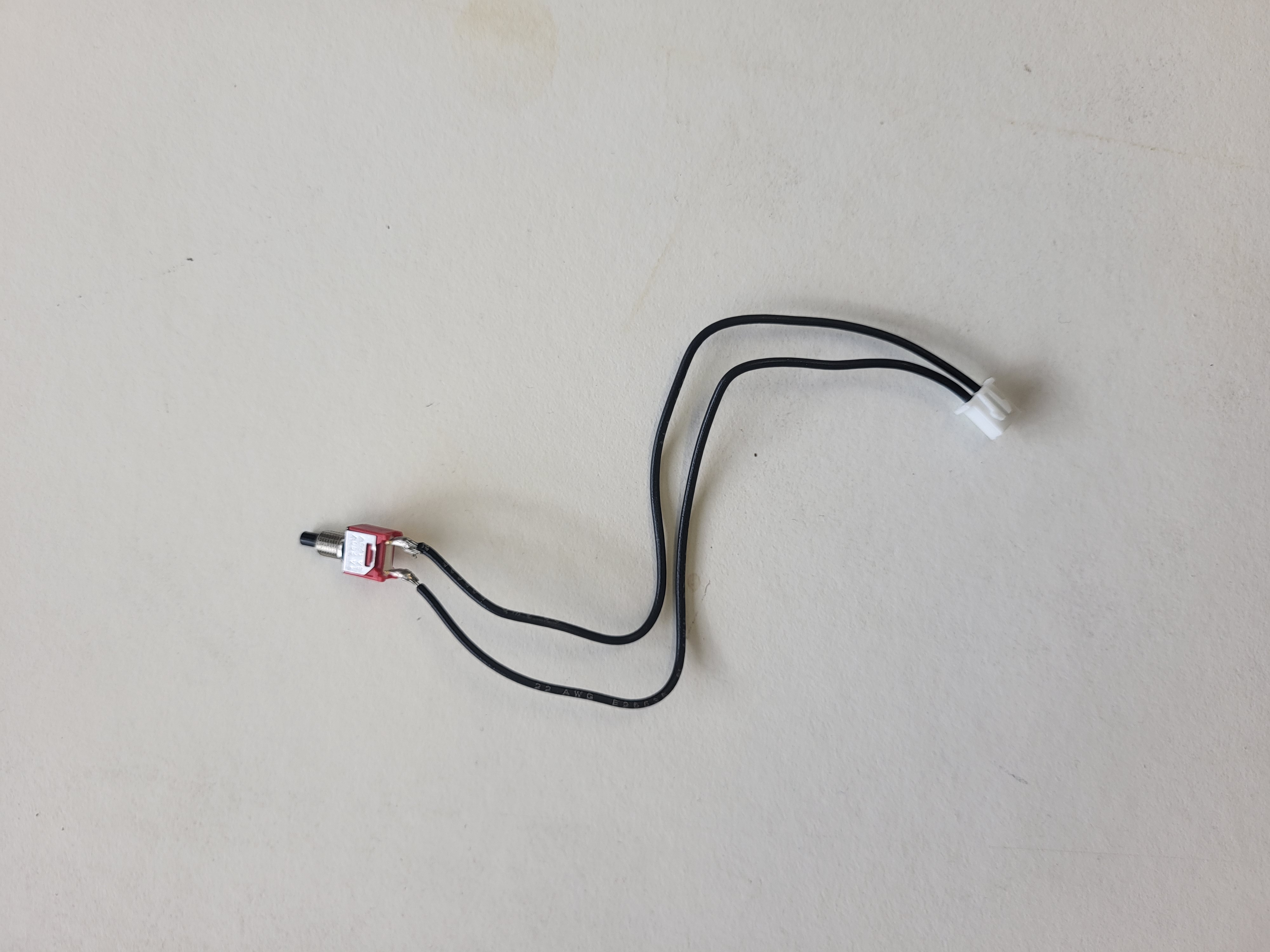
  2. For each button and flip switch, cut one crimped wire in half and solder before attaching to the JST-XH head Orientation doesn't matter.
    All switches in the panel use one crimped cable cut in half
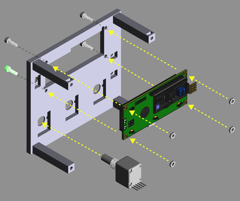
  3. Print the enclosure top and assemble as shown. Include the other rotary encoders and switches (not shown). The appropriate washers and nuts to screw onto the front face should be shipped with each component. Use M3x10 screws for the LCD. Assemble the top of the controller
  4. Use a 4-pin JST cable to connect the LCD to the marked port. Make sure the GND and VCC pins are attached to the same connection on the main and LCD board.
    • NOTE: there is a variable resistor on the back of the LCD board that adjusts the contrast, so don't screw the whole box shut until you've tested the text appears correctly
  5. Use a 5-pin JST cable for each rotary encoder. MAKE SURE the GND pin connects to the pin marked with "-" on the encoder.
  6. Plug in all the switches to the board to their closest port.
    • DO NOT PLUG SWITCHES INTO THE PORTS MARKED AS 12V/GND AS IT MAY START A FIRE AND SOME FEATURES MAY NOT WORK AS INTENDED
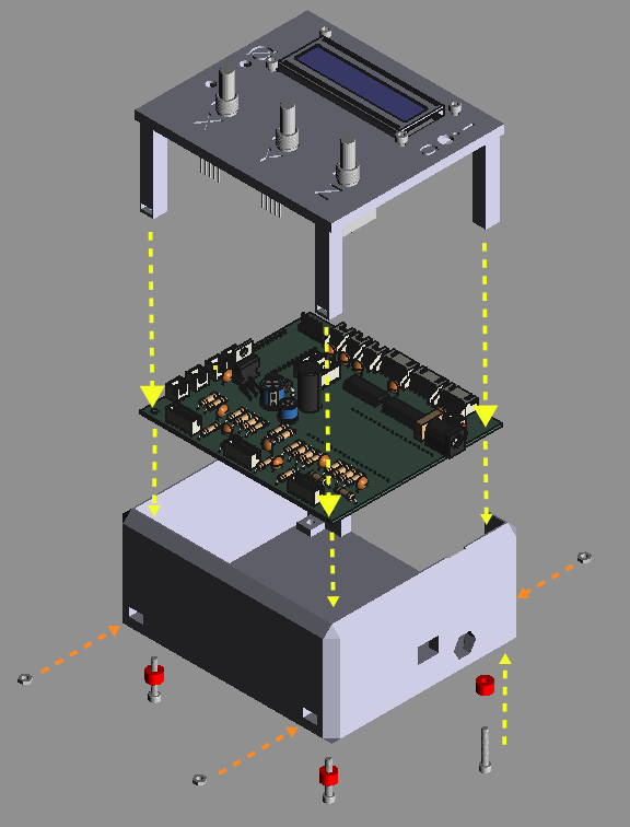
  7. Once you are confident the LCD is displaying text correctly when powered on, assemble the enclosure as shown. Make sure to print the feet in some TPU for grip. Use M3x16 (or longer).
  • Note you should have all components wired up and screwed in at this point, not all of this is shown on the diagram.

    Assemble the whole box!

Connecting to the Delta Stage

  1. Split the length (2M) of ribbon cable at the ends into 3 strips of 5 wires, and 3 strips of 2 wires. You can peel away the remaining wires and discard them.
    • Note it may be helpful for cable management not to entirely separate the 3x5 and 3x2 strips.
  2. Crimp one end of the cable, and slot into JST XH 5 or 2 cable headers respectively.
  3. Put a short length of heat-shrink tubing on each remaining end of all wires.
  4. Next, solder the remaining 3x5 wires to straight JST HX 5 pin headers (male)
    • Ensure the orientation of both ends of the cable is such that each lane could form a complete loop if it were plugged into itself without any twist. (i.e. each in and out pin is the same)
  5. Solder the sets of 2 wires to the footswitches - one to the middle-pin, the other to the pin towards the hinge of the lever.
    • Ensure this configuration is such that a circuit is made (not broken) when the switch is pressed
  6. Use hot air or a soldering iron to shrink the heat-shrink tubing and cover these solder joints.
  7. Use m2x8 screws to attach the switches to the modified feet of the Delta Stage and use these in place of the ones on the official models when assembling the actuators
    • Make sure to use the modified models found here for the open 2-photon project

Installing the I2C library

You may need to install the lib portion of the I2C code another way - the above method should work, so only follow these instructions if something is not behaving as expected.
  1. Download micropython-i2c-lcd-0.1.1.tar.gz
  2. In Thonny go to Tools > Manage Packages
    • make sure the esp32 is still plugged in to your computer
  3. Click the Install from local file link and select the .tar.gz file you downloaded
  4. CHECK: Does the file layout in the esp32 look like that on this GitHub? You should not need to but you may have to rename the folder to ensure all the code is looking in the right place...

Parts

17
QtyValueFootprintReferences
6Conn_01x04_FemaleConnector_JST:JST_XH_S4B-XH-A-1_1x04_P2.50mm_HorizontalJ1, J3, J5, J7, J8, J9
4MountingHoleMountingHole:MountingHole_3.2mm_M3H1, H2, H3, H4
3Conn_01x05_FemaleConnector_JST:JST_XH_S5B-XH-A_1x05_P2.50mm_HorizontalJ2, J4, J6
2C_SmallCapacitor_THT:C_Disc_D6.0mm_W4.4mm_P5.00mmC1, C2
2ULN2003Package_DIP:DIP-16_W7.62mm_Socket_LongPadsU1, U2

Questions

How big is the Stepper driver PCB?

It measures 62 × 98 mm and has 2 copper layers, 1.6 mm thick.

What parts does the Stepper driver use?

17 parts, built around the ULN2003. The full list of its parts is on this page, with links to each part's symbol and footprint where PCBKit's library has them.

Where can I download the Stepper driver KiCad files?

From the Open-2-Photon-Microscope/3-axis-controller repository on GitHub, at the commit this page was made from: the board is electronics/stepper_driver/stepper_driver.kicad_pcb and its schematic electronics/GPIO_expander_board/GPIO_expander_board.kicad_sch. PCBKit opens the board in the browser, with nothing to install.

Can I use the Stepper driver design in my own project?

Its repository states no licence, so its author keeps all rights: ask Open-2-Photon-Microscope before reusing the design.

More from Open-2-Photon-Microscope/3-axis-controller

3
  • 2 layers98.5 × 111 mmIntegrated board, the printed circuit board in 3D

    Integrated board

    Open-2-Photon-Microscope/3-axis-controller

    a controller system to operate motors and microscope XYZ stage

    69 parts
  • 2 layers49 × 59.5 mmGPIO expander board, the printed circuit board in 3D

    GPIO expander board

    Open-2-Photon-Microscope/3-axis-controller

    a controller system to operate motors and microscope XYZ stage

    14 parts
  • 2 layers39 × 52 mmBoard2, the printed circuit board in 3D

    Board2

    Open-2-Photon-Microscope/3-axis-controller

    a controller system to operate motors and microscope XYZ stage

    14 parts

Similar boards

  • 4 layers99.6 × 76.2 mmE TKT, the printed circuit board in 3D

    E TKT

    andreisperid/E-TKT

    open source embossed label maker

    110 parts481MIT
  • 2 layers31 × 64 mmPower driver, the printed circuit board in 3D

    Power driver

    jmfriedt/SDR-GB-SAR

    Opensource, openhardware implementation of a Software Defined Radio (SDR) Ground Based Synthetic-Aperture RADAR (GB-SAR)

    6 parts70
  • 2 layers160 × 100 mmMPCNC Nano Estlcam Shield, the printed circuit board in 3D

    MPCNC Nano Estlcam Shield

    tnn85/MPCNC-Nano-Estlcam-Shield

    Ein CNC Shield für die MPCNC in Verwendung mit Estlcam

    96 parts70
  • 2 layers42.5 × 43.2 mmElectronicFocuser, the printed circuit board in 3D

    ElectronicFocuser

    jlecomte/ascom-oag-focuser

    Open Source ASCOM-Compatible OAG Focuser For Astrophotography

    4 parts55MIT
  • 4 layers100 × 49.8 mmExpansion board, the printed circuit board in 3D

    Expansion board

    reubenstr/zuko

    A quadruped robot dog!

    75 parts51MIT
  • 2 layers75 × 60 mmDUTler V2, the printed circuit board in 3D

    DUTler V2

    TheYoctoJester/dutler

    A bench butler for your Device Under Test: turns a Raspberry Pi Pico into a USB-serial console bridge with power-relay and MOSFET strap/reset control for embedded-Linux bring-up and hardware-in-the-loop.

    54 parts23Apache-2.0
  • 4 layers76 × 82.5 mmNucleo64 CNC, the printed circuit board in 3D

    Nucleo64 CNC

    terjeio/CNC_Breakout_Nucleo64

    CNC breakout for STM324F411 and ST32F446 development boards

    120 parts22