2 layers
Modified sine inverter gwo pid
mofaa69/modified-sine-inverter-gwo-pid
TÜBİTAK 2209-A Destekli GWO-PID Kontrollü Modifiye Sinüs İnverter Tasarımı ve Uygulaması
61 parts1

 omerkarslioglu/forward_converter_pi_control1
9-36V Input Voltage, 28 Output Voltage, All Ripple: %2, 50KHz, 50 Watt DC-DC Forward Converter Design And Production
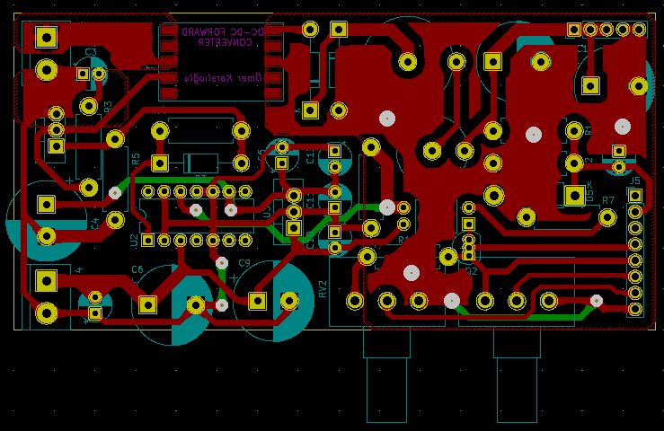
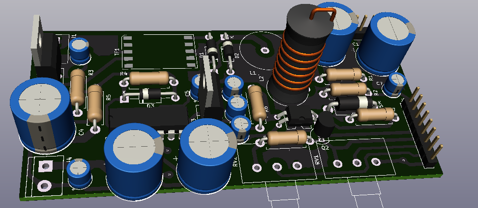
FORWARD CONVERTER is an open-source printed circuit board by omerkarslioglu, from the omerkarslioglu/forward_converter_pi_control repository on GitHub. It is a 2-layer board of 100.3 × 49.5 mm with 38 parts on 30 nets, routed with 311 tracks and 12 vias.
It is built around the IR2110L4, UF4007 and IRFZ44N. Its parts include 12 capacitors, 8 resistors, 4 diodes, 4 connectors and 3 ICs. It belongs with the power boards of this library.


9-36V Input Voltage, 28 Output Voltage, All Ripple: %2, 50KHz, 50 Watt DC-DC Forward Converter Design And Production
The aim of the project is to design and produce a dc-dc forward converter according to following requirements: Vin: 36-9 V, Vout: 28 V, Power: 50 Watt, Ripple Ratings: 2%, Fsw : 50 KHz, Control System: PI with a STM32F4 MCU. In addition to this, this paper shows formulas, calculations, experimental and simulation results of dc-dc forward converter.
A forward converter is a switched-mode power supply (SMPS) circuit that transfers energy to secondary side from primary side and ensures to decrease secondary side input voltage. Forward converter circuit is similar to the fly-back converter circuit but it is more efficient than fly-back converter circuit. Forward converter is mainly used for the application which requires higher power output. Secondary side of forward converter basicly derives from buck converter. But forward converter can increase or decrease the input voltage thanks to transformer. Forward converter is an isolated circuit as it has transformer.
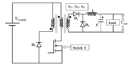
As per the above block diagram, when the switch is turned ON, the input is applied to the primary winding of the transformer and a voltage is appeared at the secondary winding of transformer. Therefore, the dot polarity of the windings of transformer is positive, due to this the diode D1 gets forward biased. Then the output voltage of the transformer is fed to the low pass filter circuit which is connected to the load. When switch is turned OFF, the current in the windings of transformer comes down to zero (assuming the transformer to be ideal). A typical forward converter consists of a: Transformer which is either a step-up or step-down with a single or multiple secondary windings. The type used depends on the available input voltage and desired output voltage. It also provides isolation of the load from the input voltage.
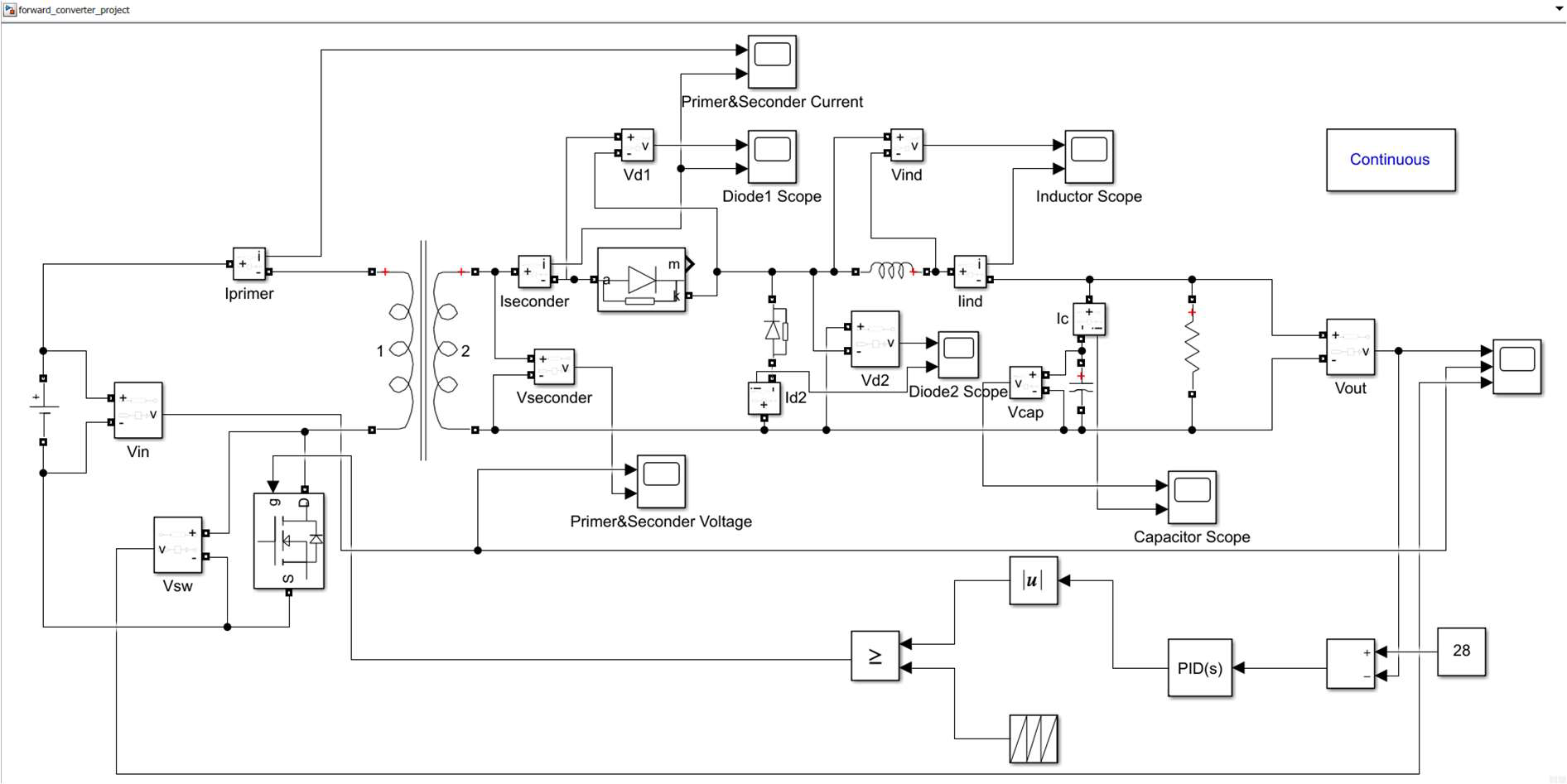
The all calculations, values and simulations result in the report.
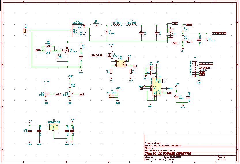
As it is known, this designed circuit is designed as a close loop system and will be controlled by
PI. The software of this circuit works as follows: voltage is read with ADC and required ratio
calculation is made. This calculated value enters the PI algorithm and is compared with the
setpoint. If this value is not the same as the setpoint, the PI calculates a new value close to or the
same as the setpoint. This value is again proportioned and the PWM signal driving the mosfet is
updated again.
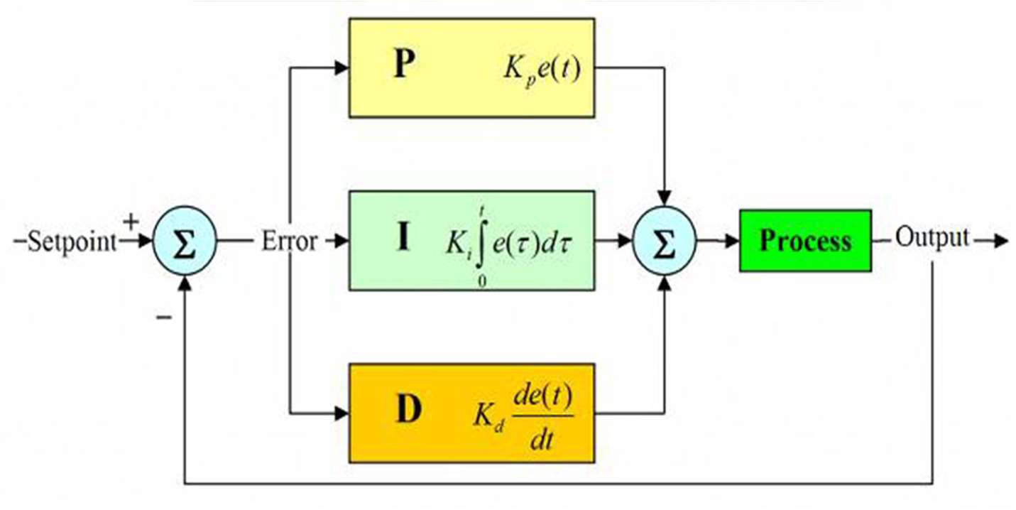
The closed loop system of Forward Converter is as above diagram. It is PID system. But Kd equals 0 as seting PI. The software generally consists of two or three main modules:
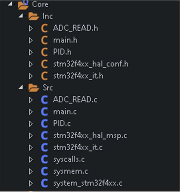
All necessary explanations are in the software modules in the software folder in the project file.
Product:
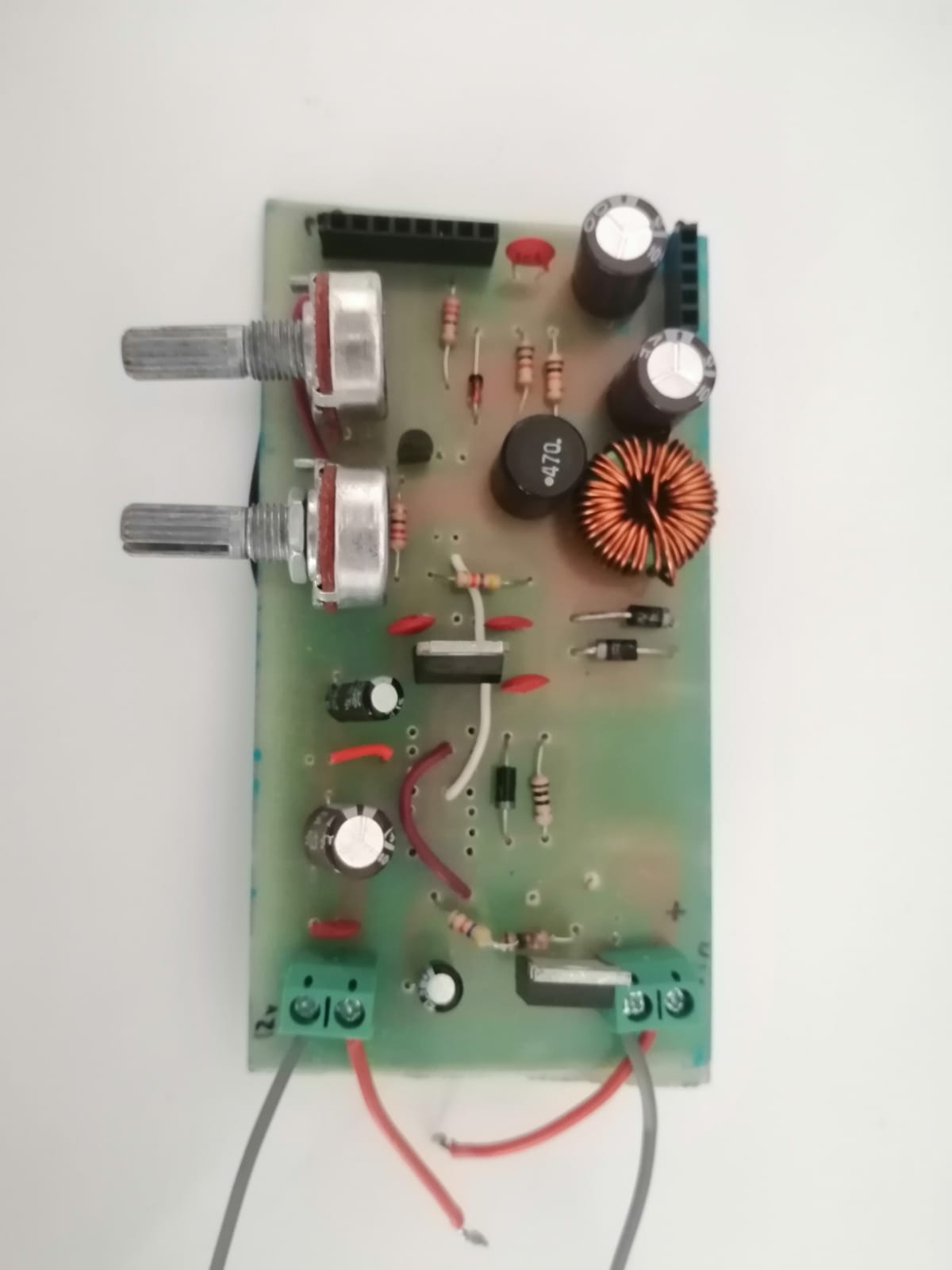
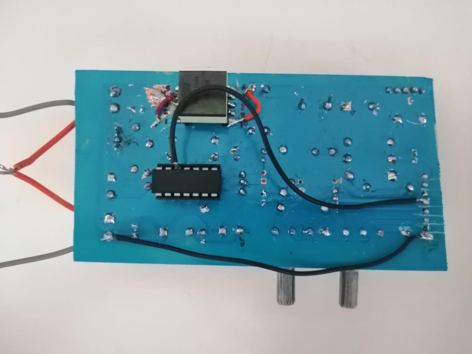
If you have any question, you can contact me.
Omer Karslioglu omerkarsliogluu@gmail.com
| Qty | Value | Footprint | References |
|---|---|---|---|
| 6 | 100nF | Capacitor_THT:CP_Radial_D5.0mm_P2.50mm | C5, C7, C8, C10, C11, C12 |
| 3 | UF4007 | Diode_THT:D_DO-41_SOD81_P12.70mm_Horizontal | D1, D2, D3 |
| 2 | 10 | Resistor_THT:R_Axial_DIN0411_L9.9mm_D3.6mm_P12.70mm_Horizontal | R3, R4 |
| 2 | 10uF | Capacitor_THT:CP_Radial_D12.5mm_P5.00mm | C4, C9 |
| 2 | 220 | Resistor_THT:R_Axial_DIN0411_L9.9mm_D3.6mm_P12.70mm_Horizontal | R7, R10 |
| 2 | 47K | Resistor_THT:R_Axial_DIN0411_L9.9mm_D3.6mm_P12.70mm_Horizontal | R5, R6 |
| 2 | CP | Capacitor_THT:CP_Radial_D12.5mm_P7.50mm | C1, C2 |
| 2 | R_POT | Potentiometer_THT:Potentiometer_Alps_RK163_Single_Horizontal | RV1, RV2 |
| 1 | 100k | Resistor_THT:R_Axial_DIN0411_L9.9mm_D3.6mm_P12.70mm_Horizontal | R1 |
| 1 | 10k | Resistor_THT:R_Axial_DIN0411_L9.9mm_D3.6mm_P12.70mm_Horizontal | R2 |
| 1 | 1nF | Capacitor_THT:CP_Radial_D5.0mm_P2.50mm | C3 |
| 1 | 470uF | Capacitor_THT:CP_Radial_D12.5mm_P7.50mm | C6 |
| 1 | BC317 | Package_TO_SOT_THT:TO-92_Inline | Q2 |
| 1 | Conn_01x05_Male | Connector_PinHeader_2.54mm:PinHeader_1x05_P2.54mm_Vertical | J2 |
| 1 | Conn_01x08_Male | Connector_PinHeader_2.54mm:PinHeader_1x08_P2.54mm_Vertical | J5 |
| 1 | D_Zener | Diode_THT:D_5W_P12.70mm_Horizontal | D5 |
| 1 | FORWARD_TRAFO | FORWARD_CONVERTER:FORWARD_TRAFO | TF1 |
| 1 | INDUCTOR | Inductor_THT:L_Axial_L26.0mm_D11.0mm_P5.08mm_Vertical_Fastron_77A | L2 |
| 1 | INDUCTOR | Inductor_THT:L_Axial_L26.7mm_D14.0mm_P7.62mm_Vertical_Vishay_IHA-104 | L1 |
| 1 | IR2110 | Package_DIP:DIP-14_W7.62mm | U2 |
| 1 | IRFZ44N | Package_TO_SOT_THT:TO-220-3_Vertical | Q1 |
| 1 | LM7805_TO220 | Package_TO_SOT_THT:TO-220-3_Vertical | U3 |
| 1 | PC817 | Package_DIP:DIP-4_W10.16mm | U1 |
| 1 | Vcc_IR2110 | TerminalBlock:TerminalBlock_bornier-2_P5.08mm | J4 |
| 1 | Vin | TerminalBlock:TerminalBlock_bornier-2_P5.08mm | J1 |
mofaa69/modified-sine-inverter-gwo-pid
TÜBİTAK 2209-A Destekli GWO-PID Kontrollü Modifiye Sinüs İnverter Tasarımı ve Uygulaması


Elias-Urquiza/taller-circuitos-tpi
Trabajo Práctico Integrador del Taller de Circuitos Electrónicos - FIUBA


cclienti/tig-welder
A DIY TIG welder that can be plugged to a traditionnal stick welder or to a high current source

arcoslab/open-coroco-legacy
COmpliant RObot COntroller is a free software project aiming to create an impedance controller based on a stm32 microcontroller using bldc motors and strain gauges.
It measures 100.3 × 49.5 mm and has 2 copper layers, 1.6 mm thick.
38 parts, built around the IR2110L4, UF4007 and IRFZ44N. The full list of its parts is on this page, with links to each part's symbol and footprint where PCBKit's library has them.
From the omerkarslioglu/forward_converter_pi_control repository on GitHub, at the commit this page was made from: the board is PCB_DESIGN/FORWARD_CONVERTER/FORWARD_CONVERTER.kicad_pcb. PCBKit opens the board in the browser, with nothing to install.
Its repository states no licence, so its author keeps all rights: ask omerkarslioglu before reusing the design.