2 layers90 × 39.1 mm
PWRBRD
omc8db/DigitalVoice
An open source codec2 based handheld digital radio for VHF/UHF amateur bands
61 parts1Apache-2.0
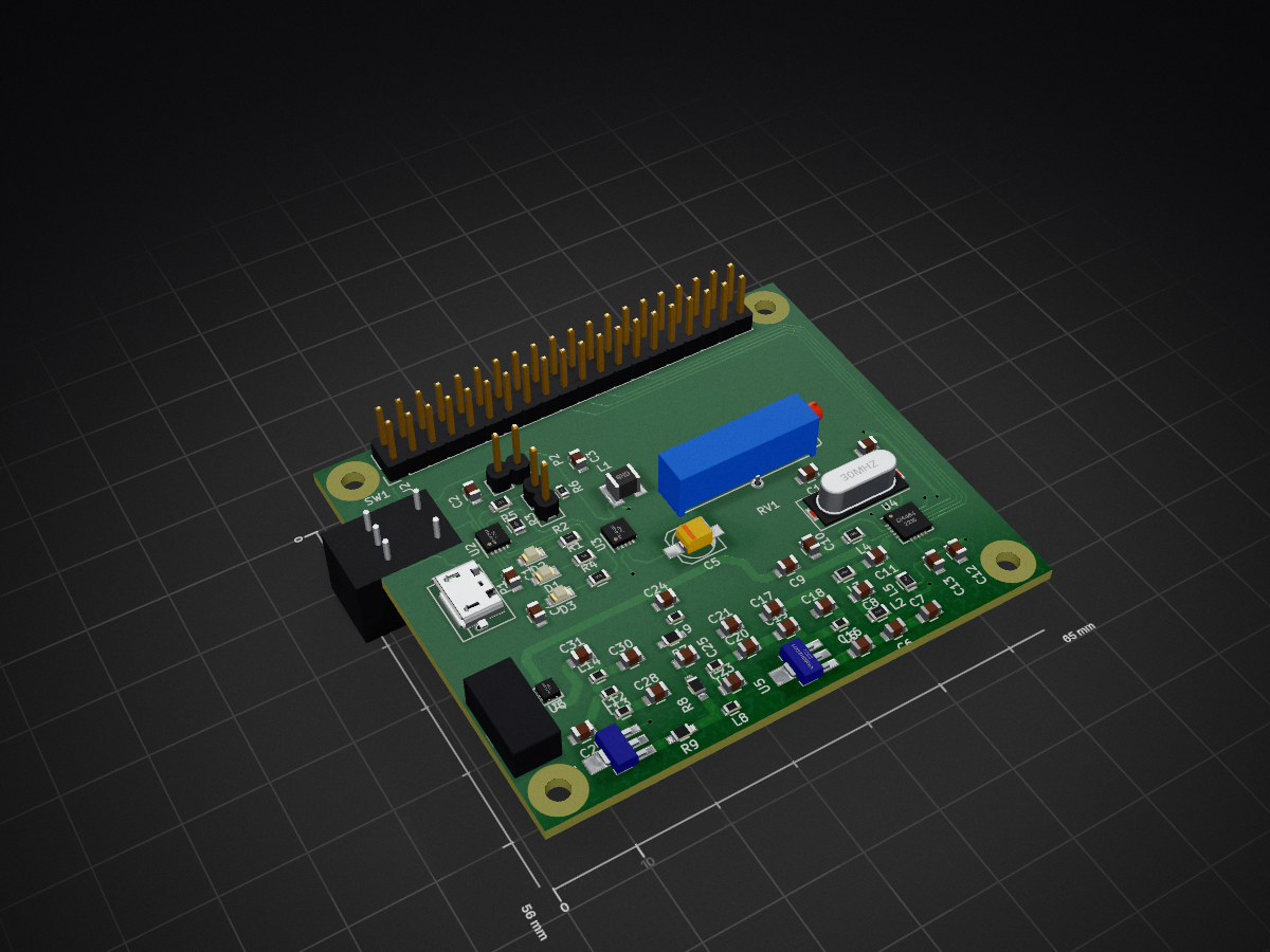
 omc8db/DigitalVoice1
An open source codec2 based handheld digital radio for VHF/UHF amateur bands
RPi Hat is an open-source printed circuit board by omc8db, from the omc8db/DigitalVoice repository on GitHub, published under the Apache-2.0 licence. It is a 2-layer board of 65 × 56 mm with 76 parts on 49 nets, routed with 369 tracks and 10 vias.
It is built around the MCP3021A5-E, MMG3H21NT1 and TPS61027DRC, with the MCP73833, SI4464DY and AFT05MS003NT1 among its other parts. Its parts include 31 capacitors, 14 inductors, 9 resistors, 6 ICs and 5 connectors.


% RPi B+ Hat
This is a project template for a Raspberry Pi B+ Hat.
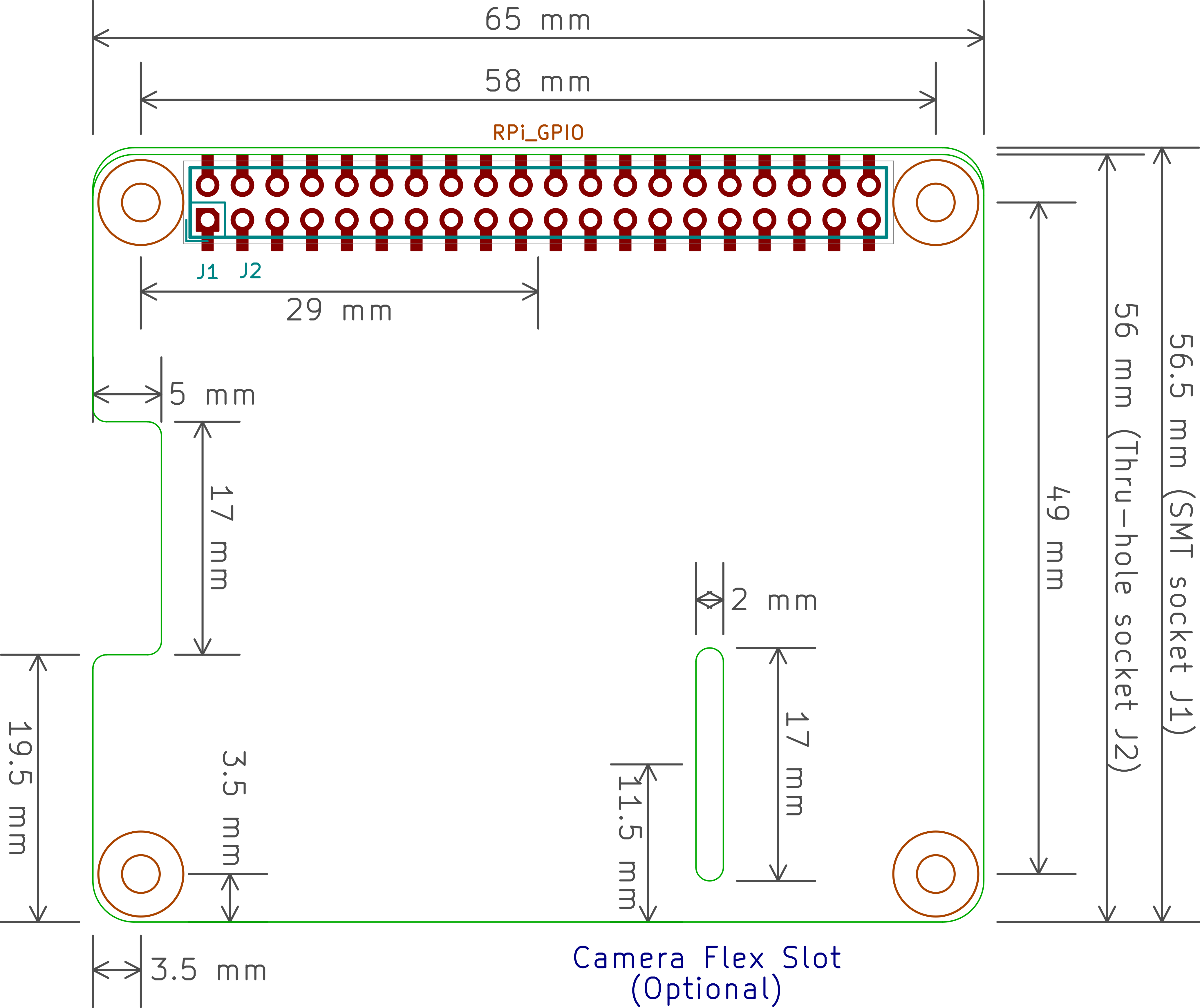
This base project includes a PCB edge defined according to this specification. Both a thru-hole and a surface mount connector are provided, along with a different PCB edge for each. Just keep the PCB edge and connector type that you're using for your design and delete the others.
The component footprints used in this template are here.
The board outline looks like this:
To use the Raspberry Pi Hat template with the through-hole connector, do the following:
To use the Raspberry Pi Hat template with the SMD connector, do the following:
(c)2015 XESS Corp.
| Qty | Value | Footprint | References |
|---|---|---|---|
| 16 | C | Capacitors_SMD:C_0805 | C16, C17, C18, C19, C20, C21, C22, C23, C24, C25, C26, C27, C28, C29, C30, C31 |
| 9 | L_Small | Resistors_SMD:R_0603 | L6, L7, L8, L9, L10, L11, L12, L13, L14 |
| 5 | 1K | Resistors_SMD:R_0805 | R1, R2, R3, R4, R5 |
| 4 | RPi_Hat:RPi_Hat_Mounting_Hole | , , , | |
| 4 | 10uF | Capacitors_SMD:C_0805 | C1, C2, C3, C4 |
| 3 | 4.7pF | Capacitors_SMD:C_0805 | C6, C9, C11 |
| 3 | LED | LEDs:LED_0805 | D1, D2, D3 |
| 3 | R | Resistors_SMD:R_0603_HandSoldering | R7, R8, R9 |
| 2 | 10nF | Capacitors_SMD:C_0805 | C12, C13 |
| 2 | 20pF | Capacitors_SMD:C_0805 | C14, C15 |
| 2 | 36nH | Resistors_SMD:R_0805 | L4, L5 |
| 1 | 11nH | Resistors_SMD:R_0805 | L2 |
| 1 | 12pF | Capacitors_SMD:C_0805 | C8 |
| 1 | 150K | Resistors_SMD:R_0603 | R6 |
| 1 | 27nH | Resistors_SMD:R_0805 | L3 |
| 1 | 30MHz | Crystals:Crystal_SMD_HC49-SD | Y1 |
| 1 | 47uF | Capacitors_SMD:c_elec_5x5.3 | C5 |
| 1 | 5.1pF | Capacitors_SMD:C_0805 | C7 |
| 1 | 5.6pF | Capacitors_SMD:C_0805 | C10 |
| 1 | 6.8uH | inductor:BOURNES_SRN4018 | L1 |
| 1 | AFT05MS003N | TO_SOT_Packages_SMD:SOT89-3_Housing_Handsoldering | Q1 |
| 1 | BATT | Pin_Headers:Pin_Header_Straight_1x02 | P2 |
| 1 | MCP3021 | TO_SOT_Packages_SMD:SOT-23-5 | U1 |
| 1 | MCP73833 | Housings_DFN_QFN:DFN-10-1EP_3x3mm_Pitch0.5mm | U2 |
| 1 | MMG3H21NT1 | TO_SOT_Packages_SMD:SOT89-3_Housing_Handsoldering | U5 |
| 1 | POT | Potentiometers:Potentiometer_Bourns_3006W_Angular_ScrewFront | RV1 |
| 1 | PWR_VOL | rotary_potentiometer:rotary_potentiometer | SW1 |
| 1 | RPi_GPIO | RPi_Hat:Pin_Header_Straight_2x20 | J2 |
| 1 | SKY13374 | RFBRD:QFN_12_2mmx2mm_0.5PITCH | U6 |
| 1 | SMACONN | RF BW Filter:SMA_Edge_Mount | J1 |
| 1 | Si4464 | Housings_DFN_QFN:QFN-20-1EP_4x4mm_Pitch0.5mm | U4 |
| 1 | THERM | Pin_Headers:Pin_Header_Straight_1x02 | P3 |
| 1 | TPS61027 | Housings_DFN_QFN:DFN-10-1EP_3x3mm_Pitch0.5mm | U3 |
| 1 | USB_OTG | Connect:USB_Micro-B | P1 |
omc8db/DigitalVoice
An open source codec2 based handheld digital radio for VHF/UHF amateur bands

omc8db/DigitalVoice
An open source codec2 based handheld digital radio for VHF/UHF amateur bands

omc8db/DigitalVoice
An open source codec2 based handheld digital radio for VHF/UHF amateur bands

omc8db/DigitalVoice
An open source codec2 based handheld digital radio for VHF/UHF amateur bands

cernohorsky/DeltaSDR
HF Software Defined Radio Transceiver that includes ADC and DAC circuits. No soundcard is needed. Board communicates only trough one USB cable.

mankangustafsson/rs_smp_a21_repair
A21 PA stage replacement for SMP02 signal generator — obsolete MRF3866/MRF5160 transistors


tuwrraphael/inkjet-printer
Inkjet printer for printing ceramic thin films: software, electronics and CAD designs

RWTH-EBC/OSIGBApp
Open-Source Internet of Things (IoT) Gateways for Building Automation Applications

jacekidziak/RPI_DRON_HAT
Project of PCB with servo driver, battery voltage measurement, IMU, GPS and barometr
It measures 65 × 56 mm and has 2 copper layers, 1.6 mm thick.
76 parts, built around the MCP3021A5-E, MMG3H21NT1, TPS61027DRC and MCP73833. The full list of its parts is on this page, with links to each part's symbol and footprint where PCBKit's library has them.
From the omc8db/DigitalVoice repository on GitHub, at the commit this page was made from: the board is hardware/PiHat_Final/RPi_Hat.kicad_pcb. PCBKit opens the board in the browser, with nothing to install.
Its repository publishes it under the Apache-2.0 licence: you may reuse it on that licence's terms (keep the author's notice, and for a copyleft licence share your changes alike).