
2 layers48 × 55.9 mm
BM3451XXDC T28A Board
YuaXan/BM3451XXDC-T28A-Board
Rechargeable battery protection board based on BM3451 IC
84 parts5
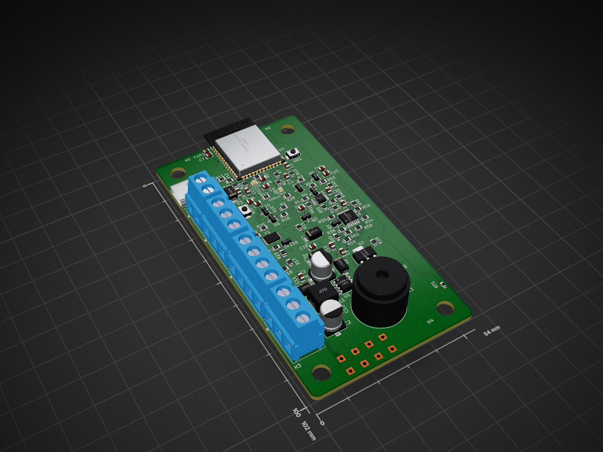
Steering-wheel-controls adapter module — ESP32-S3, KiCad schematic/PCB, JLCPCB assembly
SWC is an open-source printed circuit board by OETSolutions, from the OETSolutions/swc-module repository on GitHub. It is a 4-layer board of 54 × 102 mm with 110 parts on 80 nets, routed with 841 tracks and 163 vias.
It is built around the ESPS3-32-N4, MCP4728-E/UN and TLV9004IPWR-MS, with the XL1509-5.0E1, AMS1117-3.3 and USBLC6-2SC6 among its other parts. Its parts include 41 resistors, 23 capacitors, 12 diodes, 6 ICs and 5 connectors. It belongs with the interfaces and adapters boards of this library.


A programmable interface between a vehicle's factory steering-wheel buttons and an aftermarket Android head unit, so the buttons can be re-mapped, combined, or given press behaviours the factory wiring never had.
Status: design complete and routed; 0 DRC errors, 0 unconnected, 0 schematic/PCB parity errors. Not yet ordered.
 |  |
|---|---|
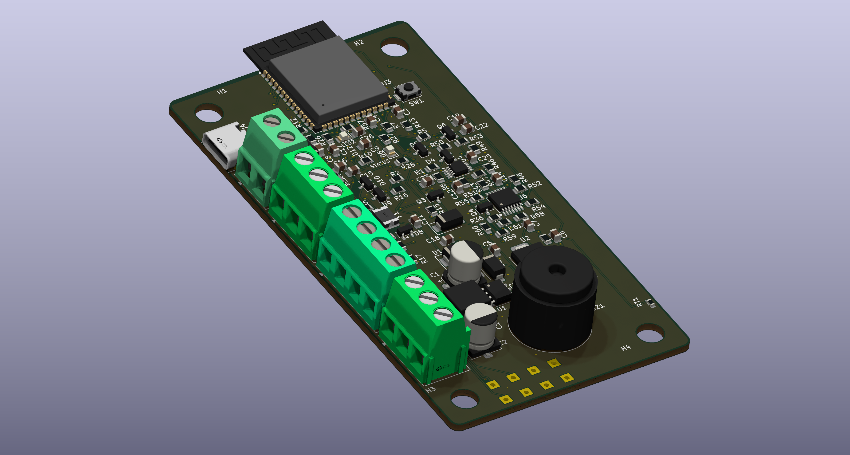
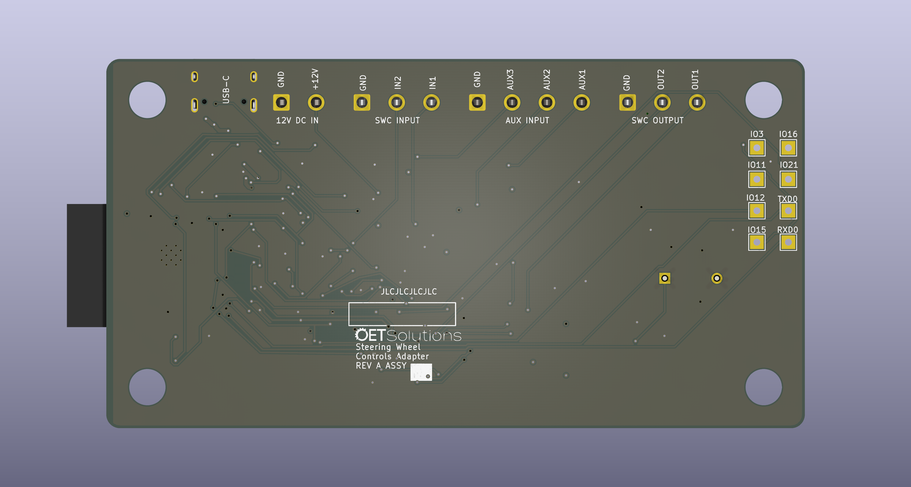
| Top — ESP32-S3 module, four left-edge screw terminals, USB-C | Bottom — connector pinouts silkscreened on the back |
| Item | Value |
|---|---|
| Board | 54.0 × 102.0 mm, 4-layer, 1.6 mm, rounded corners r ≈ 2.83 mm |
| EDA | KiCad 10 (SWC.kicad_pcb / .kicad_sch / .kicad_pro) |
| Assembly | JLCPCB, Economic PCBA, 5-off |
| Parts | 34 unique LCSC part types, JLCPCB-assembled |
| MCU | DOIT ESPS3-32-N4 (ESP32-S3-WROOM-1 clone), native USB-CDC + USB-JTAG |
A steering-wheel button is not a digital switch. It is a resistor dropped across a single analog KEY line; the head unit pulls that line up and identifies the pressed button from the voltage it reads. There are usually two such lines — this board calls them SWC1 and SWC2 — with the buttons split between them.
That arrangement is cheap and robust, and also completely fixed: the resistor values, and therefore the head unit's behaviour, live in the factory button pod. An aftermarket head unit wants a specific resistance it was taught, or one the user can program. This adapter supplies it by reading the ladder on one side and servoing the head unit's KEY line on the other, so the mapping becomes software. It can additionally send commands to the head unit over USB when a button is pressed, for actions the head unit's own steering-wheel input cannot express.
Two identical channels. The factory ladder is read by the ESP32-S3's ADC; the head unit's KEY line is driven by a closed-loop servo, so the output tracks what the board actually senses rather than what it assumes.
  SWC1  J2.3 ─R1 10k─┬─ /SWC1_ADC ─────────► U3 ADC1
  SWC2  J2.2 ─R2 10k─┴─ /SWC2_ADC ─────────► U3 ADC1
        (R15/R16 10k pull-ups to +3V3 · D4/D5 BAT54S clamp · C3/C4 100nF)

  AUX1  J5.4 ─R23 1k─┬─ /AUX1_F ───────────► U3 ADC
  AUX2  J5.3 ─R24 1k─┤   /AUX2_F
  AUX3  J5.2 ─R25 1k─┴─ /AUX3_F
        (R17/R18/R19 10k pull-ups to +3V3 · D8/D9/D10 BAT54S · C15–C17 100nF)

  U3 ESP32-S3 ══ I2C, 3.3 V, R5/R6 10k pull-ups ══ U4 MCP4728  (VDD = +3V3,
       │                                              VREF = VDD, 0–3.3 V FS)
       │                                              ┌ A ─ signal, ch 1
       │                                              ├ B ─ gain mode, ch 1
       │                                              ├ C ─ signal, ch 2
       │                                              └ D ─ gain mode, ch 2
       │
       └─ per channel:  U4.VOUTx ─R46 100k─► U6x− ─(C24 100nF fb)─► U6x out
                                          U6x+ ◄─ R58 82k ─ V_buf
                                              ◄─ R61 100k ─ V_ADJ (VOUTB/D)
                        U6x out ─R52 1k─► Q4 gate ─► Q4 drain = KEY line
                        KEY ─R36 1M─► U6y buffer ─┬─► R54 10k / R50 10k ─► /SENSEx ─► U3 ADC
                                                   └─► R58 (feedback above)

12 V ─ J1 ─ F1 PPTC ─► /+12V_SW ─► D1 SMBJ18A ─► U1 XL1509-5.0 ─► L1 47µH ─┐The three ideas that make it work:
V_KEY = (1 + R58/R61)·V_DAC − (R58/R61)·V_ADJ, so the gain is a resistor ratio and the offset is a second
DAC channel. That gives runtime range switching between 3 V and 5 V head
units, and it is why the ESP32 needs no DAC of its own (the S3 has none).Full description, including the analog detail, the power path, the USB front end, and the reasoning behind each component choice: DESIGN.md.
| Document | Contents |
|---|---|
| MANUAL.md | How to install and use the adapter — wiring, learning buttons, bindings, the app, firmware updates, troubleshooting |
| DESIGN.md | Requirements, block diagram, theory of operation, design rules, key design decisions |
| MANUFACTURING.md | BOM generation, part list, assembly-cost analysis, fabrication output, ordering decisions |
| CHANGELOG.md | Revision history, accepted limitations, open items |
| AGENTS.md | How to work on the files — rules, MCP servers, skills, verify loop, gotchas. CLAUDE.md points here. |
| tools/README.md | The sanctioned direct-write scripts, in detail |
The live project is SWC.kicad_sch / SWC.kicad_pcb / SWC.kicad_pro /
SWC.kicad_sym / the two library tables. 3dmodels/ and
footprints/logo.pretty/ are required project-local assets; tools/ holds the
sanctioned direct-write scripts; SWC-backups/ and SWC2-backups/ are the
restore path; old/ is the 2022 RP2040 design, kept for reference only. The
full annotated layout, including what is git-ignored, is in
AGENTS.md.
This board was developed with a small set of external tools, all worth citing:
uvx --from mcp-server-kicad mcp-server-kicad) — the MCP server providing
byte-preserving schematic, PCB, ERC/DRC and manufacturing-export tools. It is
the reason every change here is scriptable and repeatable.https://pcbparts.dev/mcp) — component search, JLCPCB stock and
cross-reference, reference-board lookup, and PCB design rules. Used for the
part-selection and stock-availability pass.npx skills add American-Embedded/kistack.jlcpcb-component-finder (part search by
keyword, package, stock and price) and jlcpcb-bom-generate-from-kicad (KiCad
BOM/position → JLCPCB PCBA order format), with its database refreshed from
jlcparts.The per-tool notes and the working rules for this repository live in AGENTS.md.
| Qty | Value | Footprint | References |
|---|---|---|---|
| 18 | 10k | Resistor_SMD:R_0805_2012Metric | R1, R2, R5, R10, R13, R15, R16, R17, R18, R19, R29, R50, R51, R54, R55, R56 +2 |
| 13 | 100nF | Capacitor_SMD:C_0805_2012Metric | C3, C4, C7, C15, C16, C17, C18, C19, C22, C23, C24, C25, C26 |
| 8 | TestPoint | TestPoint:TestPoint_THTPad_2.0x2.0mm_Drill1.0mm | TP1, TP2, TP3, TP4, TP5, TP6, TP7, TP8 |
| 7 | 100k | Resistor_SMD:R_0805_2012Metric | R28, R46, R47, R48, R49, R60, R61 |
| 7 | 1k | Resistor_SMD:R_0805_2012Metric | R7, R23, R24, R25, R26, R52, R53 |
| 5 | BAT54S | Package_TO_SOT_SMD:SOT-23 | D4, D5, D8, D9, D10 |
| 4 | 1uF | Capacitor_SMD:C_0805_2012Metric | C8, C9, C10, C12 |
| 4 | MountingHole_5.3mm_M5 | MountingHole:MountingHole_5.3mm_M5 | H1, H2, H3, H4 |
| 4 | SS34 | Diode_SMD:D_SMA | D2, D3, D7, D11 |
| 3 | 22uF | Capacitor_SMD:C_0805_2012Metric | C6, C11, C13 |
| 3 | 2N7002 | Package_TO_SOT_SMD:SOT-23 | Q3, Q4, Q6 |
| 2 | 100uF/50V | Capacitor_SMD:CP_Elec_6.3x7.7 | C1, C2 |
| 2 | 1M | Resistor_SMD:R_0805_2012Metric | R36, R43 |
| 2 | 22R | Resistor_SMD:R_0805_2012Metric | R11, R12 |
| 2 | 5.1k | Resistor_SMD:R_0805_2012Metric | R8, R9 |
| 2 | 82k | Resistor_SMD:R_0805_2012Metric | R58, R59 |
| 2 | GREEN | LED_SMD:LED_0805_2012Metric | D6, D12 |
| 1 | 1.0A | Fuse:Fuse_0805_2012Metric | F2 |
| 1 | 1.5A | Fuse:Fuse_1812_4532Metric | F1 |
| 1 | 100R | Resistor_SMD:R_0805_2012Metric | R27 |
| 1 | 10k B3380 | Resistor_SMD:R_0603_1608Metric | RT1 |
| 1 | 10uF | Capacitor_SMD:C_0805_2012Metric | C5 |
| 1 | 12V_DC_IN | TerminalBlock_CUI:TerminalBlock_CUI_TB007-508-02_1x02_P5.08mm_Horizontal | J1 |
| 1 | 47uH | Inductor_SMD:L_Sunlord_MWSA0605S | L1 |
| 1 | AMS1117-3.3 | Package_TO_SOT_SMD:SOT-223-3_TabPin2 | U2 |
| 1 | AUX_IN | TerminalBlock_CUI:TerminalBlock_CUI_TB007-508-04_1x04_P5.08mm_Horizontal | J5 |
| 1 | BOOT | Button_Switch_SMD:SW_SPST_TS-1088-xR020 | SW1 |
| 1 | ESPS3-32-N4 | RF_Module:ESP32-S3-WROOM-1 | U3 |
| 1 | LOGO | logo:LOGO | G1 |
| 1 | MCP4728 | Package_SO:MSOP-10_3x3mm_P0.5mm | U4 |
| 1 | RESET | Button_Switch_SMD:SW_SPST_TS-1088-xR020 | SW2 |
| 1 | SMBJ18A | Diode_SMD:D_SMB | D1 |
| 1 | SWC_IN | TerminalBlock_CUI:TerminalBlock_CUI_TB007-508-03_1x03_P5.08mm_Horizontal | J2 |
| 1 | SWC_OUT | TerminalBlock_CUI:TerminalBlock_CUI_TB007-508-03_1x03_P5.08mm_Horizontal | J3 |
| 1 | TLV9004IPWR | Package_SO:TSSOP-14_4.4x5mm_P0.65mm | U6 |
| 1 | TMB12A05 | Buzzer_Beeper:MagneticBuzzer_StarMicronics_HMB-06_HMB-12 | BZ1 |
| 1 | USB-C 2.0 16P | Connector_USB:USB_C_Receptacle_HRO_TYPE-C-31-M-12 | J4 |
| 1 | USBLC6-2SC6 | Package_TO_SOT_SMD:SOT-23-6 | U8 |
| 1 | XL1509-5.0 | Package_SO:SOIC-8_3.9x4.9mm_P1.27mm | U1 |
It measures 54 × 102 mm and has 4 copper layers, 1.6 mm thick.
110 parts, built around the ESPS3-32-N4, MCP4728-E/UN, TLV9004IPWR-MS and XL1509-5.0E1. The full list of its parts is on this page, with links to each part's symbol and footprint where PCBKit's library has them.
From the OETSolutions/swc-module repository on GitHub, at the commit this page was made from: the board is SWC.kicad_pcb and its schematic SWC.kicad_sch. PCBKit opens the board in the browser, with nothing to install.
Its repository states no licence, so its author keeps all rights: ask OETSolutions before reusing the design.
YuaXan/BM3451XXDC-T28A-Board
Rechargeable battery protection board based on BM3451 IC


igorilla666/water-controller
Scheda di controllo basata sul modulo Waveshare ESP32-S3-ETH, con ingressi sensore, RS-485, pilotaggio rele, buzzer e alimentazione/protezioni dedicate.


frindaddy/digichiver
Archival hardware/firmware for the MM54104 Digitalker chip


Cadburies/SisuAssistant
Sailing yacht Sisu: Home Assistant + ESPHome Marine Board (alternator regulation, tanks) + MQTT kernel, Signal K/Grafana/InfluxDB on a NAS, and Sisu Nav chart & weather-routing cockpit.
