6 layers100 × 100 mm
 CoretechR/PicoLab327
Web-GUI Embedded Multitool
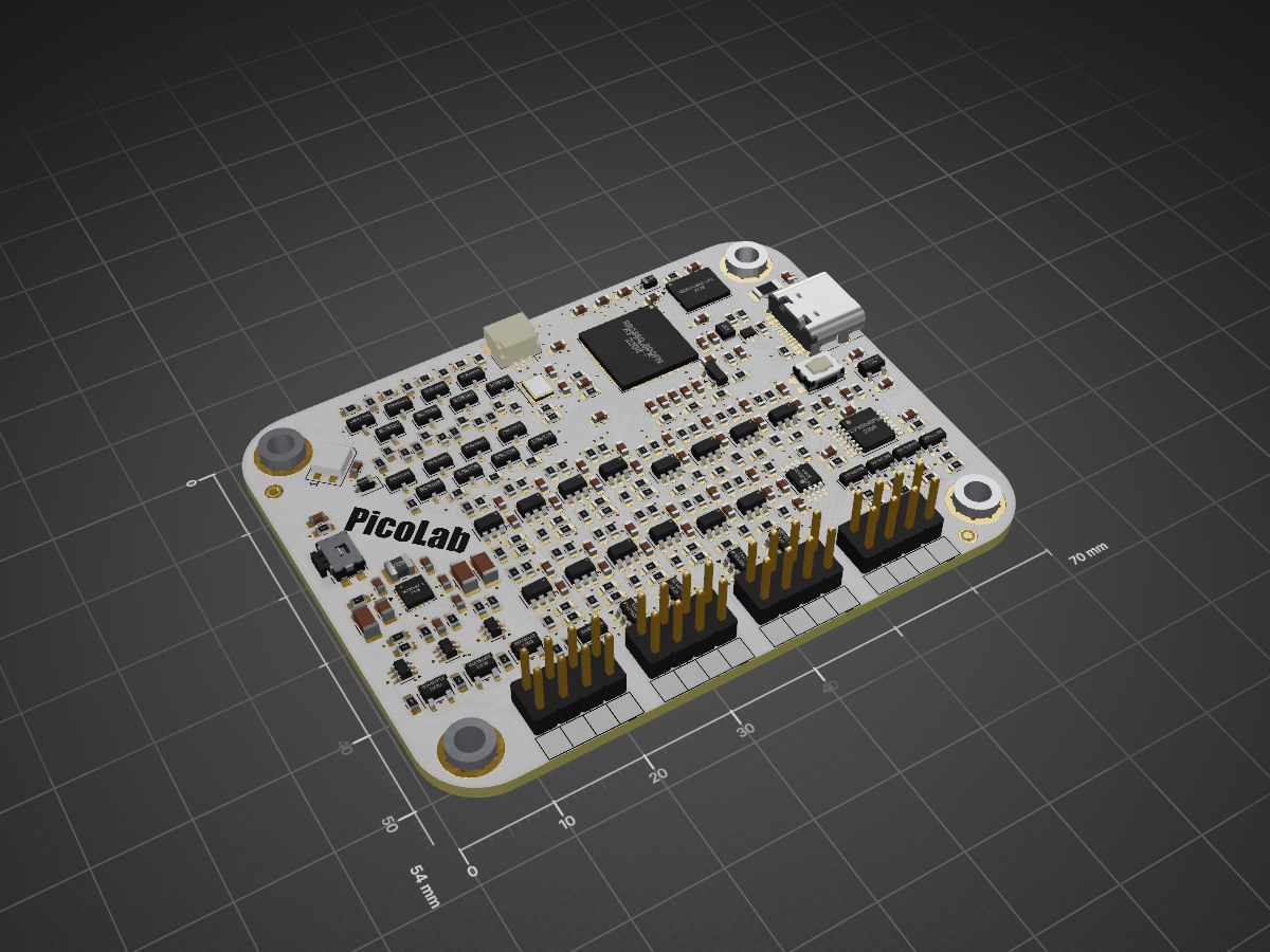
PicoLab is an open-source printed circuit board by CoretechR, from the CoretechR/PicoLab repository on GitHub, published under the GPL-3.0 licence. It is a 4-layer board of 70 × 54 mm with 285 parts on 176 nets, routed with 2,224 tracks and 330 vias.
It is built around the IS25LP064D-JKLA3-TR, TLV9004IPWR-MS and SN74LVC1T45DBV, with the SRV05-4, LM66100DCK and AP2112K-3.3 among its other parts. Its parts include 129 resistors, 69 capacitors, 32 ICs, 16 transistors and 8 diodes. It belongs with the interfaces and adapters and sensors and measurement boards and the RP2040 and RP2350 boards of this library.



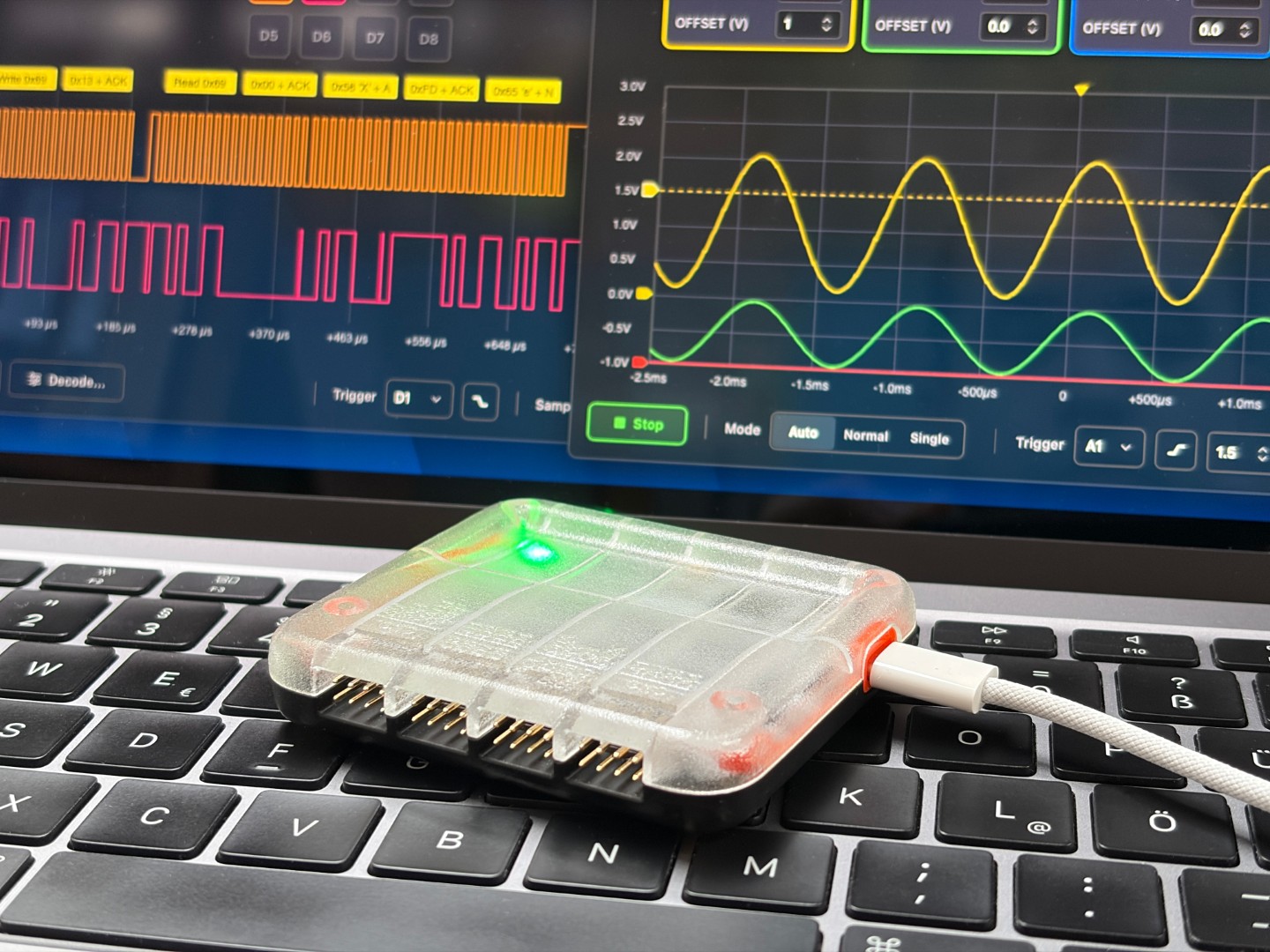
Pico.Lab is an open-source embedded bring-up tool built around the Raspberry Pi RP2350 microcontroller. It offers an easy-to-use, window-based web user interface directly served from on-device flash over a virtual USB Ethernet link. No host software or drivers are required - just plug it in and open your browser. The interface provides a 4-channel scope, an 8-channel logic analyzer, and an adjustable power supply with real-time monitoring. It also integrates GPIO control, a data logger, and bus masters for UART, SPI, and I2C communication.
.csv export functionality.Pico.Lab is built entirely on native, lightweight frameworks to maximize the RP2350's performance.
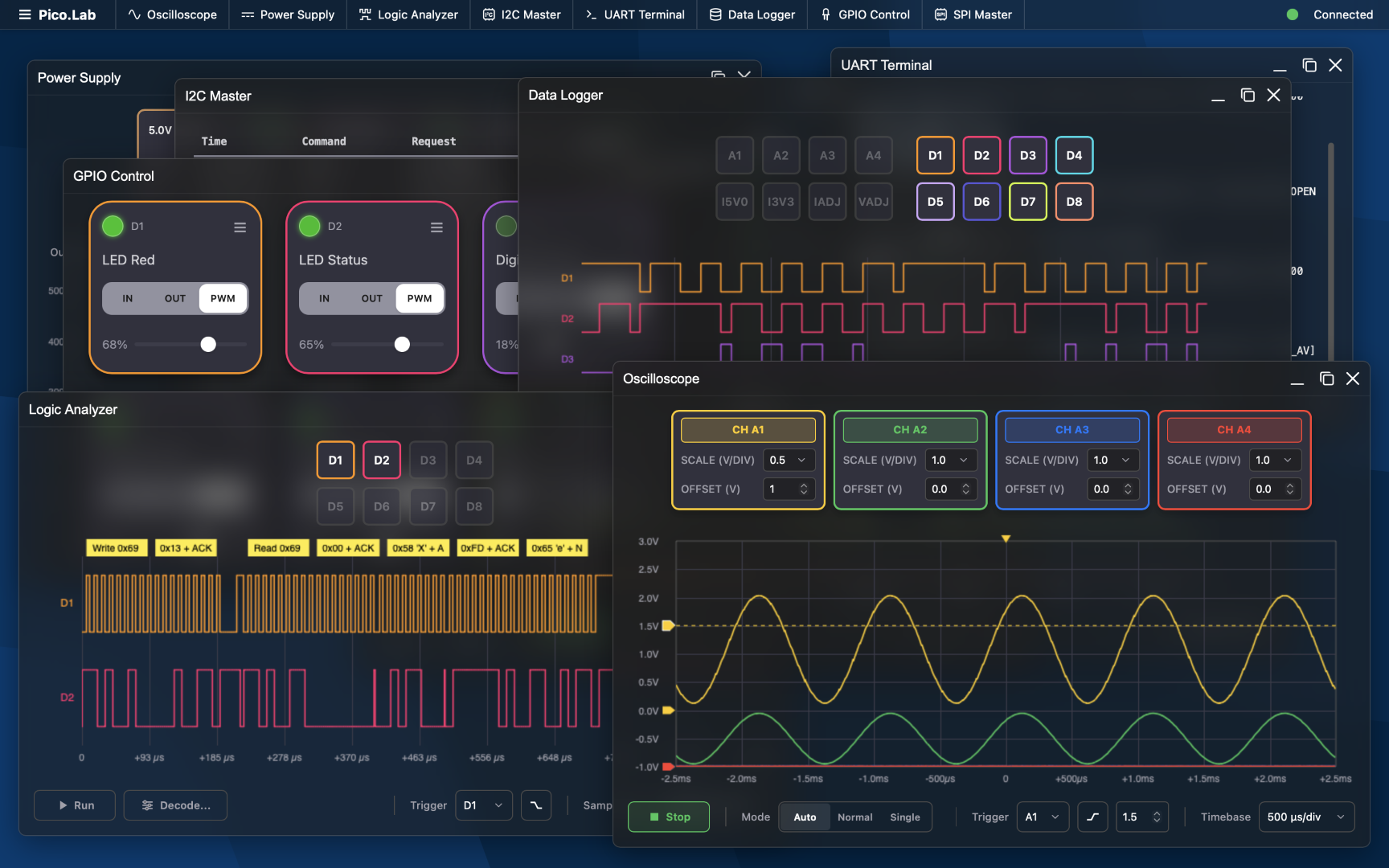
pico.lab), and the embedded HTTP server.Pico.Lab is designed to run best on the custom Pico.Lab board, but is fully compatible with standard Raspberry Pi Pico (RP2040) and Raspberry Pi Pico 2 (RP2350) boards out of the box. So if you have a Pico lying around, give the .uf2 files a try!
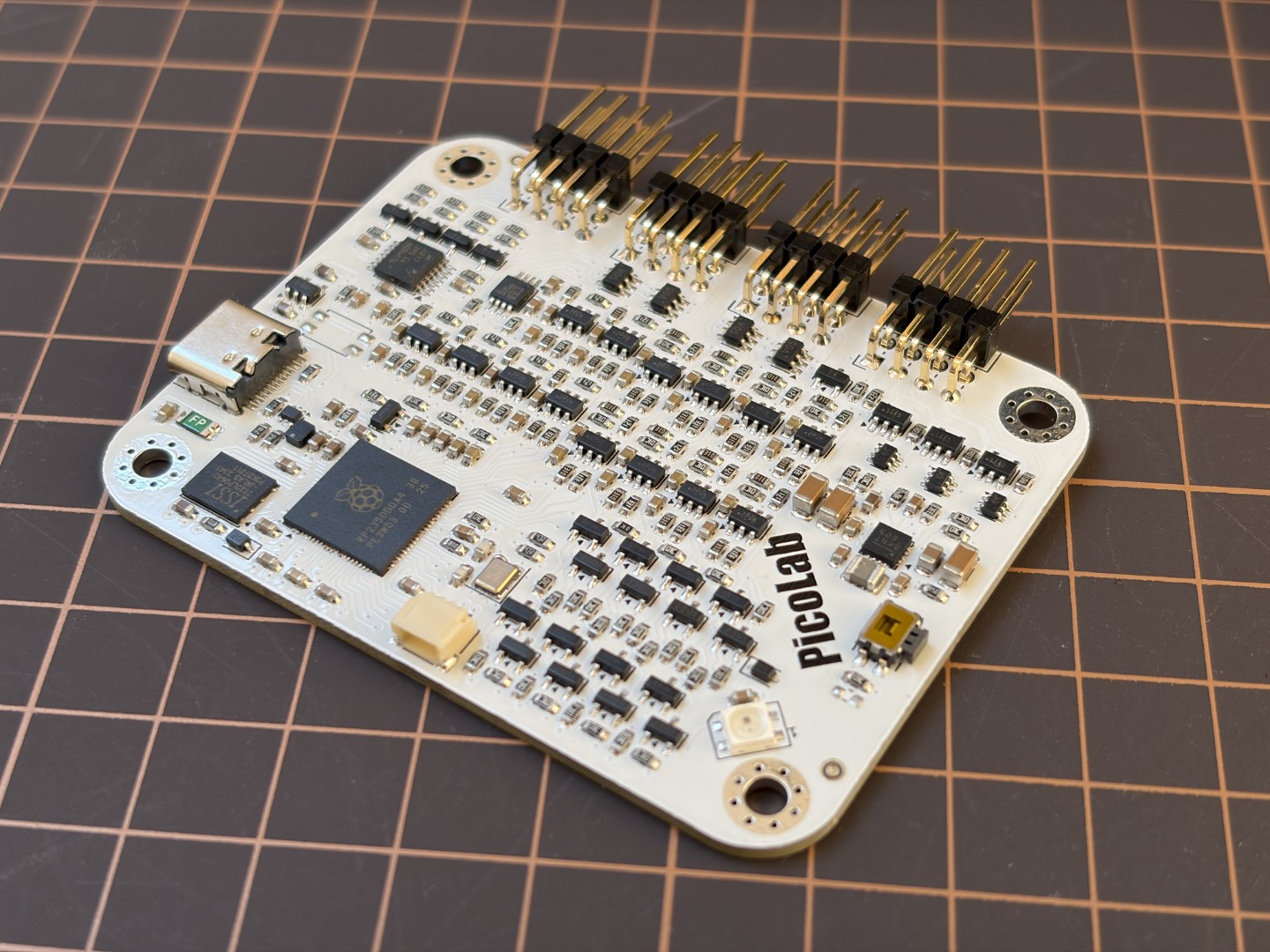
The Pico.Lab board adds the following features:
My main goal for this project was to be an easy-to-use toolkit for simple debugging applications. You want to know why an I2C sensor does not respond, what current your Wifi module is drawing or why a servo does not move? Just plug your hardware in and start debugging without checking a manual first. But since this is running on a 1$ microcontroller over a USB 1.1 link, don't expect the performance of professional instruments. The Pico will do significantly worse than any dedicated scope or logic analyzer. However, with the existing hardware there is still room for improvements, for example:
If you prefer a command-line interface, Pico.Lab also acts as a standard USB Serial (CDC) device. Connect via your favorite serial terminal (e.g., PuTTY) at 115200 baud.
Type help to see a list of commands (e.g., gpio, adc, power, i2c, spi, sys).
git clone https://github.com/CoretechR/picolab.git
cd picolab
mkdir build && cd build
cmake ..
make -j$(nproc)
Select your type of Raspberry Pi Pico board in the Pico SDK. For the Pico.Lab board, set the PICOLAB_HW_CUSTOM_BOARD define in board_config.h. You can also use this file to modify the pins for GPIO, SPI, I2C and UART.
Flash the resulting .uf2 file to your board by holding the BOOTSEL button while plugging it in, then drag-and-drop the file to the RPI-RP2 drive.
While I remain pessimistic about the impact of AI on humanity, there is no putting it back in the box. For this project, I tried to embrace it and used it heavily to generate the firmware, web frontend and parts of the documentation. I wanted to see what I could achieve in the same amount of time that I normally put into my hobby projects. All art, design and architecture were conceived by me.
This project is licensed under the GPL-3.0 License - see the LICENSE file for details. Copyright © 2026 Maximilian Kern.
| Qty | Value | Footprint | References |
|---|---|---|---|
| 50 | 100nF | Capacitor_SMD:C_0603_1608Metric | C12, C13, C18, C24, C27, C28, C30, C31, C32, C33, C34, C35, C36, C37, C38, C39 +34 |
| 40 | 10K | Resistor_SMD:R_0603_1608Metric | R106, R107, R108, R109, R114, R115, R116, R117, R118, R120, R122, R124, R126, R127, R128, R129 +24 |
| 28 | 1M | Resistor_SMD:R_0603_1608Metric | R100, R101, R110, R111, R112, R113, R130, R133, R134, R138, R140, R143, R145, R148, R150, R153 +12 |
| 14 | 120 | Resistor_SMD:R_0603_1608Metric | R62, R80, R88, R96, R119, R121, R123, R125, R136, R139, R144, R149, R154, R159 |
| 14 | 330 | Resistor_SMD:R_0603_1608Metric | R65, R75, R83, R91, R102, R103, R104, R105, R131, R135, R142, R147, R152, R156 |
| 14 | SN74LVC1T45DBV | Package_TO_SOT_SMD:SOT-23-6 | U13, U14, U19, U20, U21, U22, U23, U24, U26, U28, U30, U31, U32, U33 |
| 8 | BSS138 | Package_TO_SOT_SMD:SOT-23 | Q4, Q6, Q8, Q10, Q15, Q16, Q17, Q18 |
| 8 | DMG2301L | Package_TO_SOT_SMD:SOT-23 | Q3, Q5, Q7, Q9, Q11, Q12, Q13, Q14 |
| 8 | TestPoint | TestPoint:TestPoint_Pad_D1.5mm | TP4, TP5, TP6, TP7, TP8, TP9, TP10, TP11 |
| 5 | 300K | Resistor_SMD:R_0603_1608Metric | R13, R19, R22, R25, R52 |
| 5 | BAS70-04 | Package_TO_SOT_SMD:SOT-23 | D3, D4, D5, D6, D15 |
| 4 | 100 | Resistor_SMD:R_0603_1608Metric | R30, R31, R32, R33 |
| 4 | 10nF | Capacitor_SMD:C_0603_1608Metric | C7, C8, C10, C11 |
| 4 | 1uF | Capacitor_SMD:C_0603_1608Metric | C6, C9, C16, C21 |
| 4 | 4.7uF | Capacitor_SMD:C_0603_1608Metric | C22, C25, C26, C29 |
| 4 | 820K | Resistor_SMD:R_0603_1608Metric | R16, R18, R21, R24 |
| 4 | Conn_02x04_Counter_Clockwise | PicoLabLib:10129382-908003BLF | J4, J5, J6, J7 |
| 4 | Fiducial | Fiducial:Fiducial_1mm_Mask2mm | FID1, FID2, FID3, FID4 |
| 4 | MountingHole | MountingHole:MountingHole_3.2mm_M3_Pad_Via | H1, H2, H3, H4 |
| 4 | SRV05-4 | Package_TO_SOT_SMD:SOT-23-6 | U15, U25, U27, U29 |
| 3 | 0R03 | Resistor_SMD:R_0603_1608Metric | R43, R44, R73 |
| 3 | 10k | Resistor_SMD:R_0603_1608Metric | R9, R53, R61 |
| 3 | 22uF | Capacitor_SMD:C_1206_3216Metric | C23, C41, C46 |
| 3 | INA180A2 | Package_TO_SOT_SMD:SOT-23-5 | U4, U8, U11 |
| 3 | LM66100DCK | Package_TO_SOT_SMD:SOT-363_SC-70-6 | U16, U17, U18 |
| 2 | 15pF | Capacitor_SMD:C_0603_1608Metric | C15, C17 |
| 2 | 1k | Resistor_SMD:R_0603_1608Metric | R2, R4 |
| 2 | 21.5k | Resistor_SMD:R_0603_1608Metric | R20, R23 |
| 2 | 27 | Resistor_SMD:R_0603_1608Metric | R10, R11 |
| 2 | 4k7 | Resistor_SMD:R_0603_1608Metric | R49, R50 |
| 2 | 5.1k | Resistor_SMD:R_0603_1608Metric | R3, R8 |
| 1 | 0.5 | Resistor_SMD:R_0603_1608Metric | R29 |
| 1 | 10uF | Capacitor_SMD:C_0805_2012Metric | C48 |
| 1 | 1N4148WS | Diode_SMD:D_SOD-323 | D1 |
| 1 | 22nF | Capacitor_SMD:C_0603_1608Metric | C47 |
| 1 | 27K | Resistor_SMD:R_0603_1608Metric | R26 |
| 1 | 3.3uH | PicoLabLib:L_pol_2016 | L3 |
| 1 | 33 | Resistor_SMD:R_0603_1608Metric | R15 |
| 1 | 330R | Resistor_SMD:R_0603_1608Metric | R12 |
| 1 | 4.7uH | Inductor_SMD:L_1008_2520Metric | L4 |
| 1 | 500mA | Fuse:Fuse_1206_3216Metric_Pad1.42x1.75mm_HandSolder | F1 |
| 1 | ABM8-272-T3 | Crystal:Crystal_SMD_Abracon_ABM8G-4Pin_3.2x2.5mm | Y1 |
| 1 | AP2112K-3.3 | Package_TO_SOT_SMD:SOT-23-5 | U6 |
| 1 | BAT54WS | Diode_SMD:D_SOD-323 | D8 |
| 1 | Conn_01x03_Pin | Connector_JST:JST_SH_SM03B-SRSS-TB_1x03-1MP_P1.00mm_Horizontal | J2 |
| 1 | IS25LP064D-JKLA3-TR | Package_SON:WSON-8-1EP_6x5mm_P1.27mm_EP3.4x4.3mm | U3 |
| 1 | LM4040D30IDBZR | Package_TO_SOT_SMD:SOT-23 | U7 |
| 1 | MP28167-A | PicoLabLib:QFN-16_3x3mm_P0.5mm_MPS | U10 |
| 1 | PI4ULS5V202 | Package_SO:MSOP-8_3x3mm_P0.65mm | U9 |
| 1 | RP2350_80QFN | PicoLabLib:QFN-80-1EP_10x10mm_P0.4mm_EP3.4x3.4mm | U1 |
| 1 | SK6812MINI | LED_SMD:LED_SK6812MINI_PLCC4_3.5x3.5mm_P1.75mm | D2 |
| 1 | SW_Push | Button_Switch_SMD:Panasonic_EVQPUM_EVQPUD | SW1 |
| 1 | SW_Push | Button_Switch_SMD:SW_SPST_EVQP2_ShortPushTravel_H2.1mm | SW2 |
| 1 | TLV9004IPWR | Package_SO:TSSOP-14_4.4x5mm_P0.65mm | U2 |
| 1 | USBLC6-2P6 | Package_TO_SOT_SMD:SOT-666 | U5 |
| 1 | USB_C_Receptacle_USB2.0 | PicoLabLib:USB_C_Receptacle_HRO_TYPE-C-31-M-12 | J1 |
The 282 most common of 285 parts.

frindaddy/digichiver
Archival hardware/firmware for the MM54104 Digitalker chip

Jh0115/Unified-Kinematic-DAQ
This project is kicad and programming to to develop a micro volume and micro-power PCB with a BNO055, BME280, SD card, and a way to send data do other boards.

shreyaslad/delta
A minature, custom-made board that controls vehicles and streams onboard telemetry.

brucemack/microlink
An open source EchoLink/AllStarLink implementation that runs on a simple microcontroller.


OETSolutions/swc-module
Steering-wheel-controls adapter module — ESP32-S3, KiCad schematic/PCB, JLCPCB assembly

nthclrd/picflash
Programmeur PIC open source en Rust : remplace MPLAB IPE/XC8 pour les PIC16, pilote les PICkit 4/5/Basic ou une carte RP2040 maison (KiCad)
It measures 70 × 54 mm and has 4 copper layers, 1.7 mm thick.
285 parts, built around the IS25LP064D-JKLA3-TR, TLV9004IPWR-MS, SN74LVC1T45DBV and SRV05-4. The full list of its parts is on this page, with links to each part's symbol and footprint where PCBKit's library has them.
From the CoretechR/PicoLab repository on GitHub, at the commit this page was made from: the board is PCB/PicoLab.kicad_pcb and its schematic PCB/PicoLab.kicad_sch. PCBKit opens the board in the browser, with nothing to install.
Its repository publishes it under the GPL-3.0 licence: you may reuse it on that licence's terms (keep the author's notice, and for a copyleft licence share your changes alike).