

2 layers80 × 60 mm
EnvMonitor
kennySzhucheng/EnvMonitor
🌡️ 智能环境监测站 | STM32F103C8T6 + FreeRTOS + ESP8266 | 温湿度/光照/测距/OLED菜单/ThingSpeak上云 | 从裸机到RTOS到KiCad PCB全流程
27 parts10

 num-9i/stm32f411-parking-sensor-node
STM32F411RE-based parking sensor node with HC-SR04 input capture, Modbus RTU/RS485, UART CLI, and custom carrier PCB.
Parking sensor node is an open-source printed circuit board by num-9i, from the num-9i/stm32f411-parking-sensor-node repository on GitHub. It is a 2-layer board of 99.1 × 91.4 mm with 14 parts on 78 nets, routed with 152 tracks and 11 vias.
It is built around the MAX3485ED and HC-SR04. Its parts include 7 resistors, 2 ICs, 2 connectors, 1 capacitor and 1 diode. It belongs with the interfaces and adapters and home automation and IoT boards of this library.
STM32F411RE 기반으로 초음파 거리 측정, 주차 상태 판정, RGB LED 표시, Modbus RTU/RS485 통신을 구현한 주차 센서 노드 프로젝트입니다.
HC-SR04의 Echo pulse를 Timer Input Capture로 비동기 측정하고, 측정 결과에 hysteresis와 entry/exit delay를 적용해 FREE / OCCUPIED / ERROR 상태를 판정합니다.
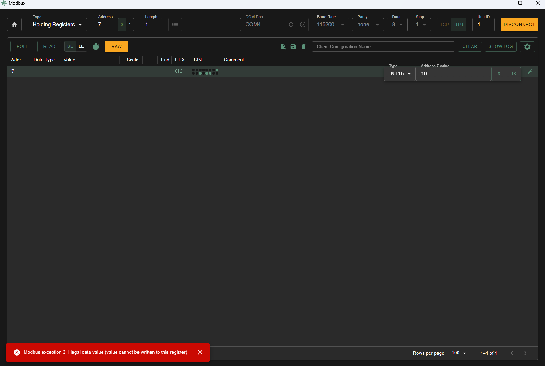
센서 상태와 설정값은 Modbus Holding Register에 매핑했으며, 0x03 Read Holding Registers와 0x06 Write Single Register를 통해 외부 Modbus Master에서 조회 및 변경할 수 있도록 구현했습니다.
현재 브레드보드 환경에서 펌웨어와 RS485 통신 검증을 완료했으며, NUCLEO-F411RE용 Carrier PCB도 Gerber/Drill 파일 생성 단계까지 완료했습니다. 실제 PCB 제작과 Bring-up은 다음 단계로 진행할 예정입니다.
0x030x06전체 데이터 흐름은 다음과 같습니다.
HC-SR04
   │
   │ Echo Pulse
   ↓
TIM2 Input Capture
   │
   ↓
Distance Measurement
   │
   ↓
Parking State Logic
FREE / OCCUPIED / ERROR
   │
   ├──────────────→ RGB LED
   │
   ↓
Modbus Register Layer
   │
   ↓
Modbus RTU
   │
   ↓
USART1 / RS485
   │
   ↓
External Modbus Master
HC-SR04의 Echo pulse는 TIM2_CH1 Input Capture로 측정합니다.
측정된 거리 값은 주차 상태 판정 로직으로 전달되며, hysteresis와 entry/exit delay를 적용해 순간적인 거리 변화로 상태가 불필요하게 전환되는 것을 줄였습니다.
판정 결과와 센서 상태, 오류 카운터, 설정값은 Modbus Holding Register에 매핑해 외부 Master에서 확인할 수 있도록 구성했습니다.
상세 핀 구성은 아래 문서를 참고합니다.
HC-SR04의 Trigger 신호를 출력한 뒤 Echo pulse의 High 구간을 측정해 거리를 계산합니다.
Echo 입력은 PA0 / TIM2_CH1에 연결하고, Timer를 1 MHz로 설정해 1 us 단위로 pulse width를 측정합니다.
IDLE
  ↓
Trigger Pulse
  ↓
WAIT_RISING
  ↓
Rising Edge Capture
  ↓
WAIT_FALLING
  ↓
Falling Edge Capture
  ↓
Pulse Width Calculation
  ↓
DATA_READY
거리 계산에는 다음 관계를 사용합니다.
Distance_mm = PulseWidth_us × 343 / 2000센서 측정 범위는 약 20 ~ 4000 mm로 제한하며, 범위를 벗어난 pulse는 Invalid Pulse로 처리합니다.
정상적인 Echo 신호가 들어오지 않을 경우 무한 대기하지 않도록 Timeout을 적용했습니다.
구분하는 오류 항목은 다음과 같습니다.
각 오류는 별도의 Counter로 기록해 Modbus를 통해 확인할 수 있습니다.
주차 상태는 다음 세 가지로 구분합니다.
| Value | State | Description |
|---|---|---|
0 | FREE | 주차 공간이 비어 있는 상태 |
1 | OCCUPIED | 차량이 감지된 상태 |
2 | ERROR | 거리 측정이 일정 시간 이상 유효하지 않은 상태 |
기본 설정값은 다음과 같습니다.
Occupied Threshold = 500 mm
Hysteresis         = 50 mm
Entry Delay        = 500 ms
Exit Delay         = 1000 ms
FREE 상태에서 거리가 Occupied Threshold 이하로 Entry Delay 동안 유지되면 OCCUPIED로 전환됩니다.
OCCUPIED 상태에서는 다음 기준을 사용합니다.
Free Threshold =
    Occupied Threshold + Hysteresis
기본값 기준으로:
Occupied Threshold = 500 mm
Free Threshold     = 550 mm
이므로 500 mm < distance <= 550 mm 구간에서는 현재 상태를 유지합니다.
따라서 임계값 부근에서 측정값이 흔들려도 상태가 즉시 반복 전환되지 않습니다.
거리 측정이 일정 시간 이상 유효하지 않을 경우 ERROR 상태로 전환합니다.
주차 상태는 RGB LED로 표시합니다.
| Parking State | LED |
|---|---|
| FREE | Green |
| OCCUPIED | Red |
| ERROR | Blue |
GPIO 구성:
PB12 → Red
PB13 → Green
PB14 → Blue
RGB LED는 Active High 방식으로 제어합니다.
외부 장치에서 센서 상태와 설정값을 확인하거나 변경할 수 있도록 Modbus RTU Slave를 구현했습니다.
지원하는 Function Code는 다음과 같습니다.
0x03 Read Holding Registers0x06 Write Single Register통신 설정:
11152008-N-1브레드보드 프로토타입에서는 자동 방향 제어 TTL-to-RS485 모듈을 사용했습니다.
PA9  / USART1_TX  → RS485 Module RXD
PA10 / USART1_RX  ← RS485 Module TXD
모듈 내부에서 송수신 방향을 자동으로 전환하므로 별도의 DE/RE GPIO가 필요하지 않습니다.
Carrier PCB에서는 MAX3485를 사용합니다.
PA9  / USART1_TX  → MAX3485 DI
PA10 / USART1_RX  ← MAX3485 RO
PB5 → MAX3485 DE + /REDE와 /RE는 하나의 GPIO로 묶어 다음과 같이 제어합니다.
PB5 LOW  → Receive Mode
PB5 HIGH → Transmit Mode
Modbus 응답을 송신하기 직전에 PB5를 HIGH로 설정하고, HAL_UART_Transmit() 완료 후 LOW로 복귀시켜 다시 Receive Mode로 전환합니다.
PCB에는 PB5에 10 kΩ Pull-down 저항을 적용해 MCU Reset 중에도 기본적으로 Driver가 비활성화되고 Receiver가 활성화되도록 구성했습니다.
브레드보드의 자동 방향 제어 모듈에는 PB5가 연결되지 않으므로, 해당 제어 코드를 추가한 뒤에도 기존 Prototype의 FC03 / FC06 통신이 정상적으로 동작하는 것을 확인했습니다.
| Address | Name | Access |
|---|---|---|
0x0000 | Distance_mm | R |
0x0001 | Parking_State | R |
0x0002 | Status_Flags | R |
0x0003 | Total_Error_Count | R |
0x0004 | Rising_Timeout_Count | R |
0x0005 | Falling_Timeout_Count | R |
0x0006 | Invalid_Pulse_Count | R |
0x0007 | Occupied_Threshold_mm | R/W |
0x0008 | Hysteresis_mm | R/W |
0x0009 | Entry_Delay_ms | R/W |
0x000A | Exit_Delay_ms | R/W |
상세한 Register Map과 설정값 검증 규칙은 아래 문서에 정리했습니다.
0x0007~0x000A Register는 Modbus 0x06 Write Single Register를 통해 실행 중에 변경할 수 있습니다.
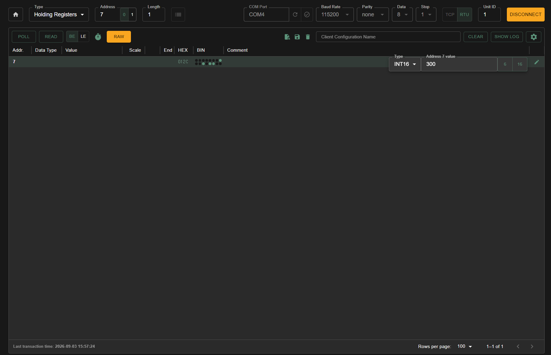
예를 들어 Occupied Threshold의 기본값은 500 mm입니다.
Register: 0x0007

500 mm
0x01F4

      ↓ FC06

300 mm
0x012C
설정값을 변경하면 주차 상태 판정 로직에서 즉시 새로운 값을 사용합니다.
현재 설정값은 RAM에만 저장되므로 Reset 또는 전원 재인가 후에는 기본값으로 돌아갑니다.
지원하지 않는 요청이나 잘못된 설정값에는 Modbus Exception Response를 반환합니다.
| Exception | Description |
|---|---|
0x01 | Illegal Function |
0x02 | Illegal Data Address |
0x03 | Illegal Data Value |
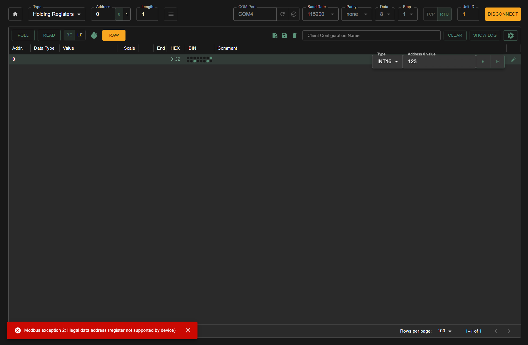
예를 들어 읽기 전용 Register인 0x0000에 0x06 Write 요청을 보내면 0x02 Illegal Data Address를 반환합니다.
허용 범위를 벗어난 Occupied Threshold를 설정하면 0x03 Illegal Data Value를 반환합니다.
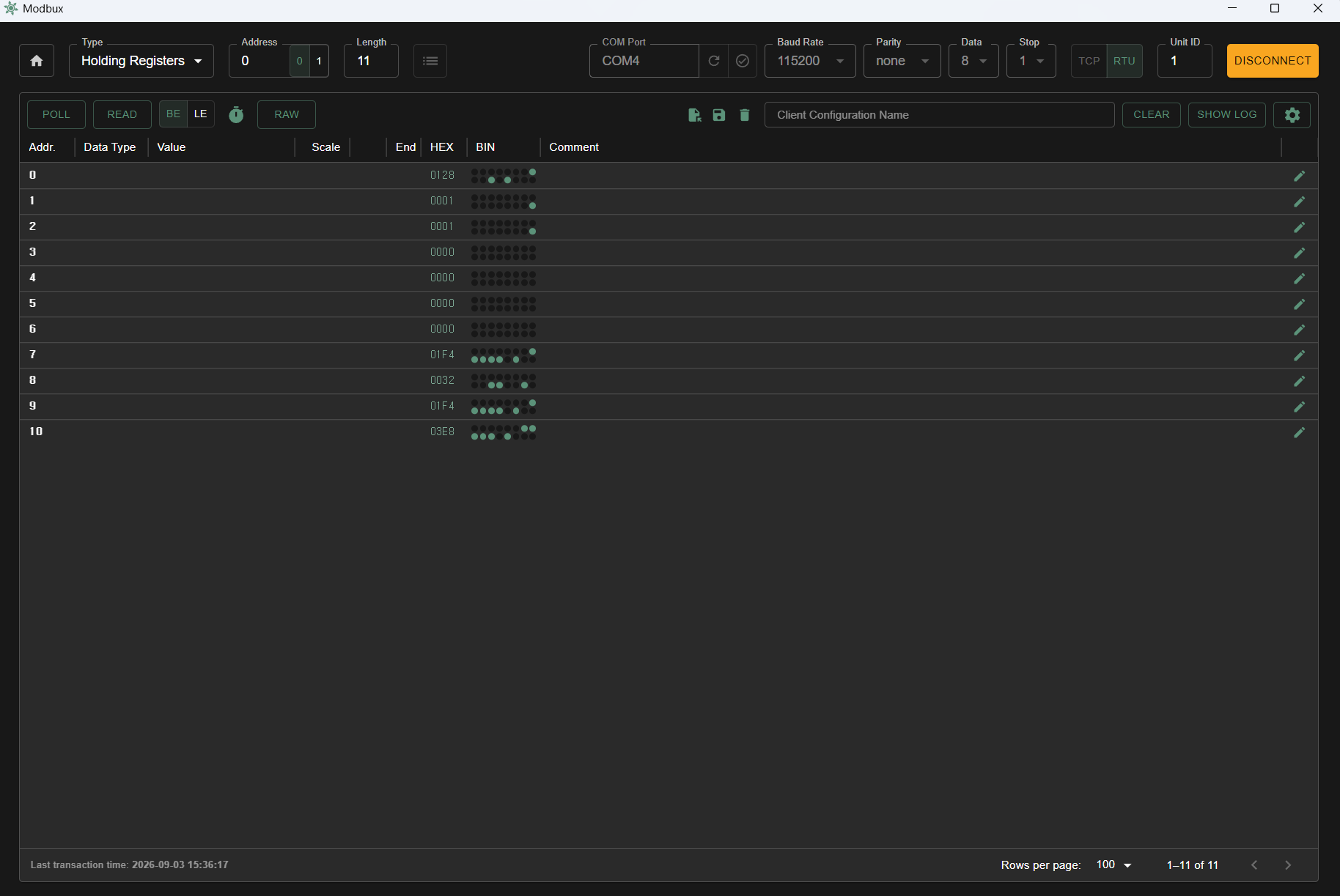
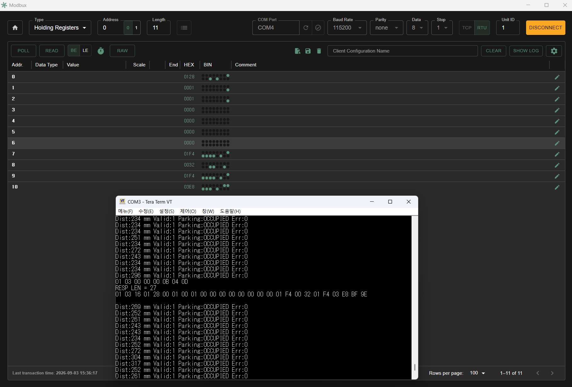
Modbus Client에서 0x0000~0x000A Register를 한 번에 읽어 거리, 주차 상태, 오류 카운터, 설정값을 확인했습니다.
UART Debug 출력을 통해 실제 Modbus RTU Request와 Response 데이터를 확인했습니다.
Occupied Threshold를 500 mm에서 300 mm로 변경한 뒤 Write 결과와 실제 주차 상태 전환 기준 변경을 확인했습니다.
읽기 전용 Register에 Write 요청을 전송해 0x02 Illegal Data Address 응답을 확인했습니다.
허용 범위를 벗어난 설정값을 전송해 0x03 Illegal Data Value 응답을 확인했습니다.
브레드보드 프로토타입을 실제 조립 가능한 구조로 확장하기 위해 NUCLEO-F411RE용 Carrier PCB를 KiCad로 설계했습니다.
Carrier PCB에는 다음 회로를 포함합니다.
RS485 종단저항은 Solder Jumper를 사용해 필요할 때만 활성화할 수 있도록 구성했습니다.
RS485_A ── 120 Ω ── JP1 ── RS485_B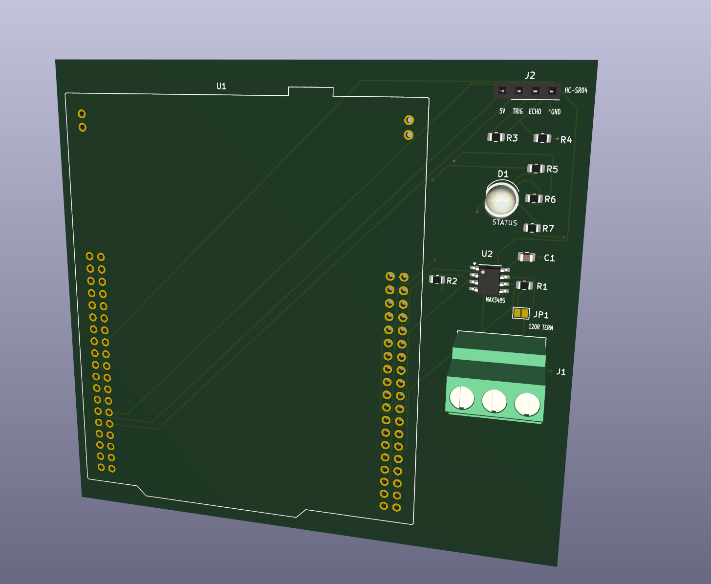
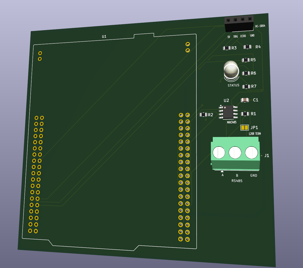
PCB는 2-Layer로 구성했으며, B.Cu에 GND Copper Zone을 적용했습니다. ERC와 DRC는 모두 Error / Warning 0건을 확인했습니다.
구매한 Common Cathode RGB LED의 B-G-K-R Pin Order에 맞춰 전용 Footprint를 추가하고, D1의 Drill Diameter를 0.8 mm로 조정해 Annular Ring 규칙을 만족시켰습니다.
이후 Gerber와 PTH / NPTH Drill File을 생성하고 KiCad Gerber Viewer에서 Edge.Cuts, Copper, Solder Mask, Silkscreen, Drill Layer를 확인했습니다.
KiCad 프로젝트와 제조용 출력 파일은 다음 경로에 포함되어 있습니다.
hardware/
└─ parking_sensor_node/
   ├─ parking_sensor_node.kicad_pro
   ├─ parking_sensor_node.kicad_sch
   ├─ parking_sensor_node.kicad_pcb
   ├─ fp-lib-table
   ├─ footprints/
   │  └─ ParkingSensor.pretty/
   │     └─ LED_D5.0mm-4_RGB_BGKR.kicad_mod
   └─ gerber/
      ├─ *.gbr
      ├─ *-PTH.drl
└─ *-NPTH.drl주요 모듈은 다음과 같이 분리했습니다.
Core/
├─ Inc/
│  ├─ hcsr04.h
│  ├─ parking_logic.h
│  ├─ rgb_led.h
│  ├─ app_config.h
│  ├─ modbus_crc.h
│  ├─ modbus_registers.h
│  └─ modbus_rtu.h
│
└─ Src/
   ├─ hcsr04.c
   ├─ parking_logic.c
   ├─ rgb_led.c
   ├─ app_config.c
   ├─ modbus_crc.c
   ├─ modbus_registers.c
   └─ modbus_rtu.c
각 모듈의 역할을 분리해 센서 측정, 상태 판정, 설정값 관리, Register Mapping, Modbus Frame 처리가 서로 직접 의존하지 않도록 구성했습니다.
현재 구현은 프로젝트 범위에 맞춰 다음과 같이 제한되어 있습니다.
0x03, 0x06만 지원현재 브레드보드 환경에서는 센서 측정, 상태 판정, RGB 표시, Modbus FC03 / FC06, Exception Response 및 RS485 실통신까지 검증했습니다.
다음 단계에서는 구매한 부품이 도착한 뒤 실제 부품과 Footprint를 대조하고 Carrier PCB 제작 및 Bring-up을 진행합니다.
제작 전 실물 기준으로 다음 항목을 확인할 예정입니다.
PCB 제작 후에는 다음 항목을 검증할 예정입니다.
Power / Ground
    ↓
HC-SR04 Measurement
    ↓
RGB State Output
    ↓
MAX3485 DE/RE Control
    ↓
Modbus FC03 / FC06
    ↓
Exception Response
    ↓
Long-term Communication Test
PCB 제작 후에는 브레드보드에서 검증한 기능을 Carrier PCB에서도 동일한 순서로 Bring-up할 예정입니다.
| Qty | Value | Footprint | References |
|---|---|---|---|
| 3 | 330R | Resistor_SMD:R_0805_2012Metric | R5, R6, R7 |
| 1 | 100nF | Capacitor_SMD:C_0805_2012Metric | C1 |
| 1 | 10k | Resistor_SMD:R_0805_2012Metric | R2 |
| 1 | 120 | Resistor_SMD:R_0805_2012Metric | R1 |
| 1 | 1k | Resistor_SMD:R_0805_2012Metric | R3 |
| 1 | 2k | Resistor_SMD:R_0805_2012Metric | R4 |
| 1 | HC-SR04 | Connector_PinSocket_2.54mm:PinSocket_1x04_P2.54mm_Vertical | J2 |
| 1 | LED_BGKR | ParkingSensor:LED_D5.0mm-4_RGB_BGKR | D1 |
| 1 | MAX3485 | Package_SO:SOIC-8_3.9x4.9mm_P1.27mm | U2 |
| 1 | NUCLEO64-F411RE | ParkingSensor:ST_Morpho_Connector_64_STLink | U1 |
| 1 | RS485_BUS | TerminalBlock_Phoenix:TerminalBlock_Phoenix_MKDS-3-3-5.08_1x03_P5.08mm_Horizontal | J1 |
| 1 | SolderJumper_2_Open | Jumper:SolderJumper-2_P1.3mm_Open_Pad1.0x1.5mm | JP1 |
It measures 99.1 × 91.4 mm and has 2 copper layers, 1.6 mm thick.
14 parts, built around the MAX3485ED and HC-SR04. The full list of its parts is on this page, with links to each part's symbol and footprint where PCBKit's library has them.
From the num-9i/stm32f411-parking-sensor-node repository on GitHub, at the commit this page was made from: the board is hardware/parking_sensor_node/parking_sensor_node.kicad_pcb and its schematic hardware/parking_sensor_node/parking_sensor_node.kicad_sch. PCBKit opens the board in the browser, with nothing to install.
Its repository states no licence, so its author keeps all rights: ask num-9i before reusing the design.
kennySzhucheng/EnvMonitor
🌡️ 智能环境监测站 | STM32F103C8T6 + FreeRTOS + ESP8266 | 温湿度/光照/测距/OLED菜单/ThingSpeak上云 | 从裸机到RTOS到KiCad PCB全流程


NikolaiRadke/Noko_2
The do-it-yourself Arduino-based Noko monster. Version 2 with PCB and 3D printed casing.

billtsol/Maze
This project demonstrates how to use an Arduino board, IR sensors, and a motor driver shield to create a maze-solving robot.

c-lydia/ESP-ROS2
A tiny robot with IMU (MPU5060) and an ultrasonic sensor (HC-SR04), running on micro-ROS, communicating over UDP.

dbrgn/crazyflie2-hcsr04
Ultrasonic sensor (HC-SR04) extension board for the Crazyflie 2.0

YousefAliAicha/aegis-embedded-system
Networked rotating ultrasonic radar system built on the Deneyap Kart 1A (ESP32-S3), with a real-time web dashboard served directly from the board.

YousefAliAicha/sentinel-arduino-firmware
Adaptive traffic-light FSM on the Arduino UNO R3 — pedestrian preemption, LDR-gated night mode with HC-SR04 vehicle detection, and a multiplexed 7-segment countdown. Fully non-blocking.