2 layers89 × 123.4 mm

 nsec/nsec-badge62
Software from the NorthSec badge
Nsec badge-2025-panel is an open-source printed circuit board by nsec, from the nsec/nsec-badge repository on GitHub. It is a 2-layer board of 197 × 249.7 mm with 375 parts on 492 nets, routed with 3,136 tracks and 404 vias.
It is built around the AP2112K-3.3TRG1(MS), HS96L03W2C03 and IR968-8C, with the TPSMF05CT1G, TSOP34838 and TYPE-C-31-M-12 among its other parts. Its parts include 100 capacitors, 56 resistors, 28 ICs, 28 connectors and 16 diodes. It belongs with the lEDs and displays and radio and wireless boards and the ESP32 and RISC-V boards of this library.


Brought to you by the Team badge of NorthSec.
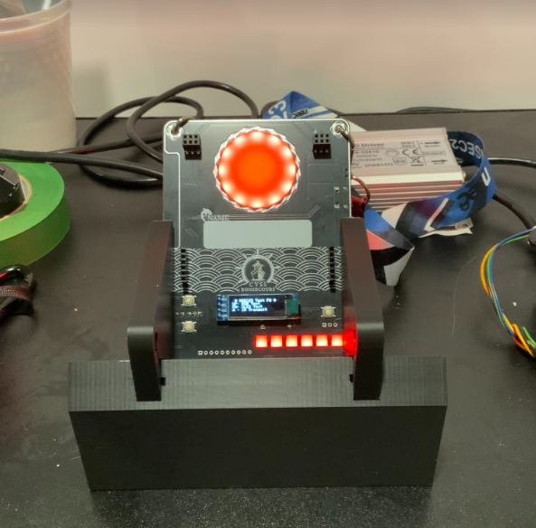
The NorthSec 2025 badge is loosely based on the ESP32-C3 design with an ESP32-C3 microcontroller (ESP32-C3-WROOM-02-N4) which is used to drive several periphery devices:
The badge is powered through a USB-C port or through 3 AAA batteries.
If you wish to hack your badge or create a new one based on the hardware. All the information is available here.
The firmware is based on the Espressif IoT Development Framework. The build system uses PlatformIO to easily manage the dependencies.
You can install it on Debian / Ubuntu in a python virtualenv with these commands:
sudo apt install python3-virtualenv

virtualenv .venv
. .venv/bin/activate

pip install platformio
The installation procedure for your OS may differ a little, please consult the PlatformIO documentation if you have any difficulties.
Once the installation is complete you can build the firmware:
# Conference firmware
pio run -e conference

# CTF firmware
pio run -e ctfFlash the firmware with this command:
# Conference firmware
pio run -t upload -e conference

# CTF firmware
pio run -t upload -e ctf
If multiple badges are connected, you can select which badge will be flash with
the --upload-port <port_name> option:
# Conference firmware
pio run -t upload -e conference --upload-port <port_name>
To improve the upload speed, you can skip the build validation/process with the
-t nobuild option:
# Conference firmware
pio run -t upload -t nobuild -e conferenceTo read the logging statements output on the USB serial interface, it is
possible to use pio device monitor or idf.py's monitor command.
However, you can use your preferred terminal emulator by pointing it to the
/dev/ttyACM0 device. The badge is configured to output at 115200 bauds,
without parity, and with one stop bit per character.
Note that electrically resetting the board using the hardware switch will cause the pseudo-terminal device to disappear, making it hard to read the logs emitted during boot.
Pulsing the DTR signal (lowering it for 1 second) will cause the board to reset without affecting the pseudo-terminal device, allowing you to read early-boot messages. This is supported by most terminal emulators.
NorthSec CTF badge 2025 is brought to you by the teamwork of:
Special thanks to:
| Qty | Value | Footprint | References |
|---|---|---|---|
| 72 | 0.1uF | Capacitor_SMD:C_0603_1608Metric | C10, C10, C10, C10, C11, C11, C11, C11, C12, C12, C12, C12, C13, C13, C13, C13 +56 |
| 72 | SK6812SIDE-A_C5378721 | footprints:LED-SMD_SK6812SIDE-A_C5378721 | RGB1, RGB1, RGB1, RGB1, RGB10, RGB10, RGB10, RGB10, RGB11, RGB11, RGB11, RGB11, RGB12, RGB12, RGB12, RGB12 +56 |
| 20 | 10K | Resistor_SMD:R_0603_1608Metric | R6, R6, R6, R6, R7, R7, R7, R7, R8, R8, R8, R8, R14, R14, R14, R14 +4 |
| 16 | 1uF | Capacitor_SMD:C_0603_1608Metric | C1, C1, C1, C1, C3, C3, C3, C3, C4, C4, C4, C4, C17, C17, C17, C17 |
| 16 | 5.1K | Resistor_SMD:R_0603_1608Metric | R2, R2, R2, R2, R3, R3, R3, R3, R4, R4, R4, R4, R5, R5, R5, R5 |
| 16 | TS-1187A-B-A-B | footprints:SW-SMD_4P-L5.1-W5.1-P3.70-LS6.5-TL_H1.5 | SW1, SW1, SW1, SW1, SW2, SW2, SW2, SW2, SW3, SW3, SW3, SW3, SW4, SW4, SW4, SW4 |
| 8 | 100K | Resistor_SMD:R_0603_1608Metric | R1, R1, R1, R1, R13, R13, R13, R13 |
| 8 | 10uF | Capacitor_SMD:C_0805_2012Metric | C2, C2, C2, C2, C18, C18, C18, C18 |
| 8 | Conn_01x06 | footprints:PinSocket_1x06_P2.54mm_Vertical | J6, J6, J6, J6, J7, J7, J7, J7 |
| 8 | FC-2012HRK-620D | footprints:LED0805-R-RD | LED1, LED1, LED1, LED1, LED2, LED2, LED2, LED2 |
| 8 | Fiducial | Fiducial | KiKit_FID_B_1, KiKit_FID_B_2, KiKit_FID_B_3, KiKit_FID_B_4, KiKit_FID_T_1, KiKit_FID_T_2, KiKit_FID_T_3, KiKit_FID_T_4 |
| 8 | LANYARD-HOLE-4mm | footprints:LANYARD-HOLE-4mm | HOLE1, HOLE1, HOLE1, HOLE1, HOLE2, HOLE2, HOLE2, HOLE2 |
| 8 | MBR120LSF | footprints:SOD-123_L2.8-W1.8-LS3.7-RD | D1, D1, D1, D1, D2, D2, D2, D2 |
| 8 | PM254-2-03-S-8_5 | footprints:HDR-SMD_6P-P2.54-V-F-R2-C3-LS7.0 | J1, J1, J1, J1, J2, J2, J2, J2 |
| 8 | SolderJumper | Jumper:SolderJumper-2_P1.3mm_Bridged_RoundedPad1.0x1.5mm | JP1, JP1, JP1, JP1, JP2, JP2, JP2, JP2 |
| 4 | 0.1uF | Capacitor_SMD:C_0805_2012Metric | C19, C19, C19, C19 |
| 4 | 1K | Resistor_SMD:R_0603_1608Metric | R12, R12, R12, R12 |
| 4 | 2479 | footprints:BAT_2479 | BT1, BT1, BT1, BT1 |
| 4 | 470 | Resistor_SMD:R_0603_1608Metric | R10, R10, R10, R10 |
| 4 | 56 | Resistor_SMD:R_0603_1608Metric | R11, R11, R11, R11 |
| 4 | AP2112K-3_3TRG1 | footprints:SOT-25-5_L2.9-W1.6-P0.95-LS2.8-BL | U6, U6, U6, U6 |
| 4 | Bus_PCI_32bit_Universal | footprints:BUS_PCI | J5, J5, J5, J5 |
| 4 | Conn_01x03_Pin | footprints:PinSocket_1x03_P2.54mm_Vertical | J4, J4, J4, J4 |
| 4 | Conn_01x10 | footprints:PinHeader_1x10_P2.54mm_Vertical | J3, J3, J3, J3 |
| 4 | ESP32-C3-WROOM-02-N4(4MB) | footprints:BULETM-SMD_ESPRESSIF_ESP32-C3-WROOM-02-N4-4MB | U1, U1, U1, U1 |
| 4 | Fuse_Small | Fuse:Fuse_1206_3216Metric_Pad1.42x1.75mm_HandSolder | F1, F1, F1, F1 |
| 4 | HS96L03W2C03 | footprints:OLED-TH_L38.0-W12.0_HS91L02W2C01 | U7, U7, U7, U7 |
| 4 | IR968-8C | footprints:LED-TH_L2.9-W2.9-P2.54-FD | U4, U4, U4, U4 |
| 4 | MMBT3904 | Package_TO_SOT_SMD:SOT-23 | Q1, Q1, Q1, Q1 |
| 4 | SSSS811101 | footprints:SW-SMD_SSSS811101 | KEY1, KEY1, KEY1, KEY1 |
| 4 | TPSMF05CT1G | footprints:SOT-363_L2.0-W1.3-P0.65-LS2.1-BL | U3, U3, U3, U3 |
| 4 | TSOP34838 | footprints:SENSOR-TH_TSOP34838 | U5, U5, U5, U5 |
| 4 | TYPE-C-31-M-12 | footprints:USB-C_SMD-TYPE-C-31-M-12 | U2, U2, U2, U2 |
| 3 | NPTH | NPTH | KiKit_TO_1, KiKit_TO_2, KiKit_TO_3 |
The 359 most common of 375 parts.


sukhjeetsekhon/KiCad-Projects
A repository of KiCad projects, PCBs, and modules that I make for fun or utility.

ste2425/PSP-Bluetooth
Formerly PSP-Consolizer, PSP-Bluetooth aims to add Bluetooth controller support to the PSP 1K/2K/3K.


Serhio4522/SEM_hitachi-
Digitization of a Hitachi scanning electron microscope (SEM) — hardware design, FPGA firmware, and analog frontend schematics.

CodeSakshamY/Half-life-HackClub
custom pcb for my psycon wearable project. designed in easyeda.


AnaviTechnology/anavi-infrared
ANAVI Infrared pHAT is an open source hardware Raspberry Pi pHAT (add-on board) for rapid prototyping of Internet of Things (IoT) powered by free and open source software. It features:
It measures 197 × 249.7 mm and has 2 copper layers, 1.6 mm thick.
375 parts, built around the AP2112K-3.3TRG1(MS), HS96L03W2C03, IR968-8C and TPSMF05CT1G. The full list of its parts is on this page, with links to each part's symbol and footprint where PCBKit's library has them.
From the nsec/nsec-badge repository on GitHub, at the commit this page was made from: the board is hw/2025/panel/nsec-badge-2025-panel.kicad_pcb and its schematic hw/2025/baseboard-with-esp32/nsec-badge-2025-baseboard.kicad_sch. PCBKit opens the board in the browser, with nothing to install.
Its repository states no licence, so its author keeps all rights: ask nsec before reusing the design.