2 layers197 × 249.7 mm

 patriq128/MyTtiny
My own development board based on the chip ATtiny3217.
MyTinny PCB is an open-source printed circuit board by patriq128, from the patriq128/MyTtiny repository on GitHub, published under the MIT licence. It is a 2-layer board of 29.7 × 17 mm with 19 parts on 34 nets, routed with 304 tracks and 38 vias.
It is built around the AP2112K-3.3TRG1(MS), SK6112MINI-RG and 2011-1X11G00SB, with the TYPE-C-31-M-12 among its other parts. Its parts include 5 resistors, 4 capacitors, 4 ICs, 2 diodes and 1 switch. It belongs with the microcontroller boards boards and the AVR (ATmega, ATtiny) boards of this library.


My own development board based on the ATtiny3217 microcontroller.
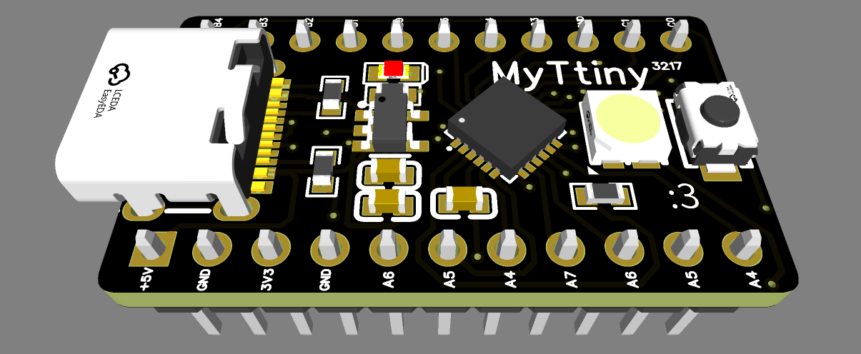
One of the main reasons I made this board was for my own projects. However, I also wanted to make it useful enough for other people to use.
Compact size
I tried to make this board as small as possible, and I think I did a pretty good job. The board measures only 29.718 × 17.018 mm.
USB-C
The board uses a USB-C connector, making it easy to power, program, and communicate with. I also included the required configuration resistors, so USB-C to USB-C cables work properly.
UART
I decided to add a CH340N USB-to-UART converter. This allows the board to communicate with a computer through USB and makes it possible to upload programs and use a serial monitor.
NeoPixel LED
I wanted the board to provide visual feedback without requiring any external hardware, so I added a programmable RGB LED.
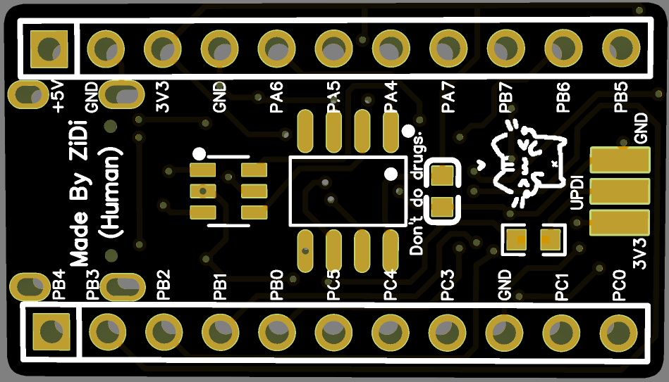
Labeled Pins
Every header pin is labeled on both the top and bottom sides of the PCB, making it easier to identify the pins regardless of which side of the board you are looking at.
For this board, I decided to use the ATtiny3217. It is small, power-efficient, and capable enough for a wide range of simple embedded projects.
The board uses a USB-C connector. I chose USB-C because it is compact, modern, and convenient to use.
I also added a USB protection chip to help protect the USB data lines from electrical faults.
The USB interface is connected to a CH340N USB-to-UART converter, which provides serial communication between the computer and the ATtiny3217.
There are two voltage levels available on the board:
I also added a small red LED to indicate when the board is powered.
The board includes an SK6812MINI programmable RGB LED. It can be controlled by the ATtiny3217 and used to display different colors or provide visual feedback.
There is also a small user button that can be used for any purpose in your code.
Before uploading your first program, you need to install a bootloader on the ATtiny3217.
The bootloader can be uploaded using the three UPDI pins located at the bottom of the board.
For this project, I am using the bootloader provided by MegaTinyCore.
Once the bootloader is installed, you can upload programs and use the serial monitor through the USB-C port connected to the CH340N USB-to-UART converter.
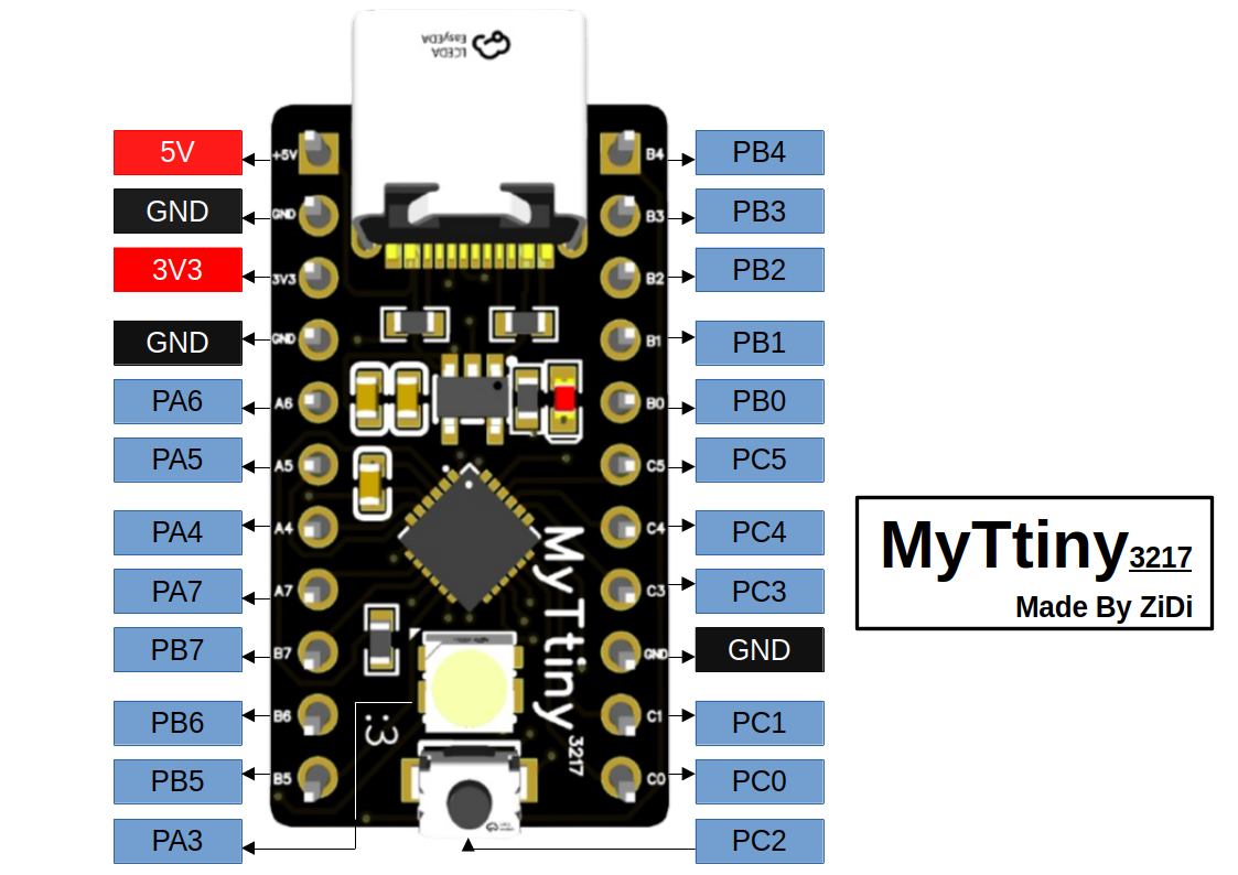
The name of every pin is printed on both the top and bottom sides of the PCB.
Note: On the top side, the pins are labeled without the "P" prefix.
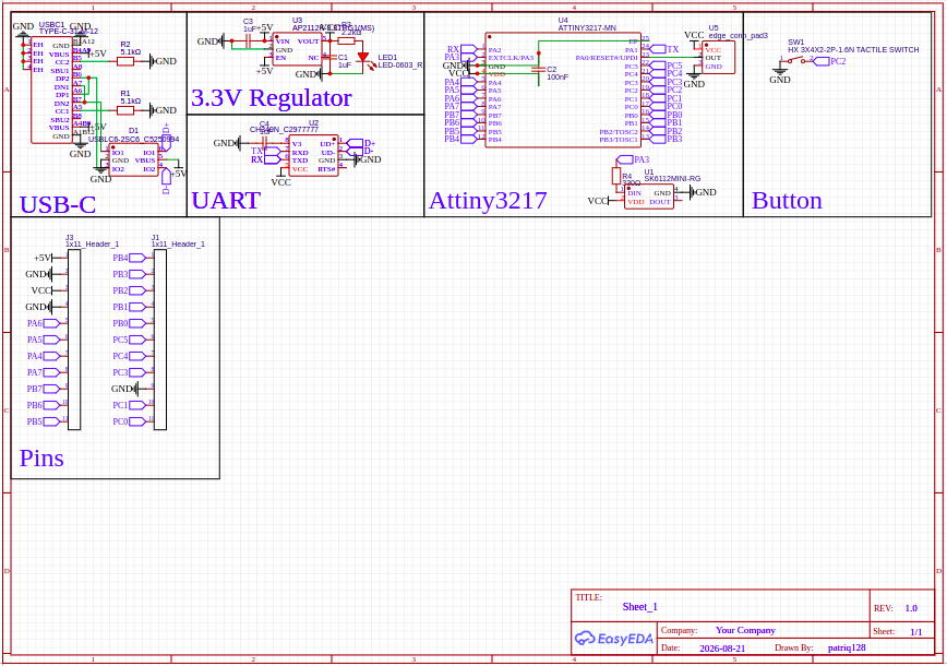
I tried to make the schematic as clean and easy to understand as possible.
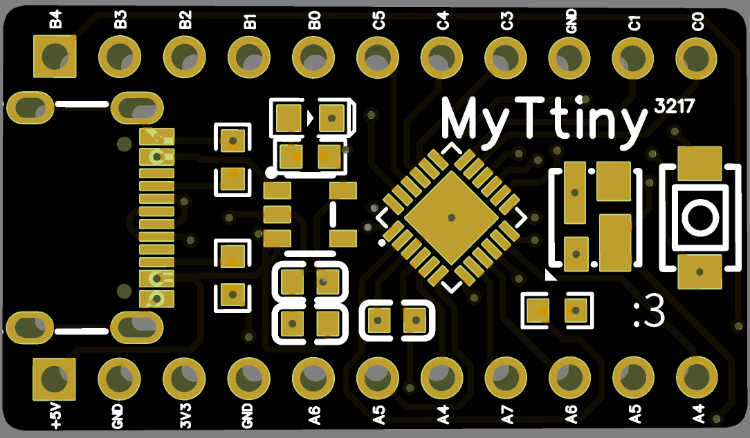
The main goal of this project is to have the board manufactured. I plan to have it manufactured by JLCPCB, which will manufacture the PCBs and assemble the components for me.
In the production folder, you can find:
Honestly, I originally made this board because I was bored.
I also didn't really want to use some of the existing development boards available to me, so I decided to design my own.
I chose the ATtiny3217 as the main microcontroller because I wanted to try something different instead of using more common chips such as the RP2040 or ESP32.
In the end, it became a small development board that I can use for my own projects while also making the design available for anyone else who might find it useful.
| Qty | Value | Footprint | References |
|---|---|---|---|
| 3 | 1uF | C0603 | C1, C3, C4 |
| 2 | 2011-1X11G00SB | HDR-TH_11P-P2.54_2011-1X11G00SB | H1, H2 |
| 2 | 5.1kΩ | R0603 | R1, R2 |
| 1 | 100nF | C0603 | C2 |
| 1 | 1kΩ | R0603 | R5 |
| 1 | 2.2kΩ | R0603 | R3 |
| 1 | 330Ω | R0603 | R4 |
| 1 | AP2112K-3.3TRG1(MS) | SOT-23-5_L2.9-W1.6-P0.95-LS2.7-BR | U3 |
| 1 | CH340N_C2977777 | SOP-8_L4.9-W3.9-P1.27-LS6.0-BL | U2 |
| 1 | HX 3X4X2-2P-1.6N TACTILE SWITCH | KEY-SMD_L4.0-W3.0-LS4.9-1 | SW1 |
| 1 | LED-0603_R | LED0603_RED | LED1 |
| 1 | SK6112MINI-RG | LED-SMD_4P-L3.7-W3.5-SK6812SMINI-001 | U1 |
| 1 | TYPE-C-31-M-12 | USB-C_SMD-TYPE-C-31-M-12_1 | USBC1 |
| 1 | USBLC6-2SC6_C5250994 | SOT-23-6_L2.9-W1.6-P0.95-LS2.8-BL | D1 |
| 1 | edge_conn_pad3 | PADPAD4X1.5 3PAD_SIGNALS | U5 |


CodeSakshamY/Half-life-HackClub
custom pcb for my psycon wearable project. designed in easyeda.

rogerclarkmelbourne/STM32_Pill_Boards
Various STM32 boards in a form factor similar to the Maple Mini or Blue Pill board


audiodestrukt/einhander
One-handed MIDI controller: parametric enclosure (build123d) + 4-layer RP2040 USB-MIDI PCB (tscircuit/KiCad)

tscircuit/rp2040-lipo-charger
Rechargeable RP2040 controller with USB-C, 1S LiPo charging, battery monitoring, and an OLED interface

pierrechevalier83/ferris
A low profile split keyboard designed to satisfy one single use case elegantly
It measures 29.7 × 17 mm and has 2 copper layers, 1.6 mm thick.
19 parts, built around the AP2112K-3.3TRG1(MS), SK6112MINI-RG, 2011-1X11G00SB and TYPE-C-31-M-12. The full list of its parts is on this page, with links to each part's symbol and footprint where PCBKit's library has them.
From the patriq128/MyTtiny repository on GitHub, at the commit this page was made from: the board is PCB/KiCad/MyTinny_PCB.kicad_pcb and its schematic PCB/KiCad/MyTinny_PCB.kicad_sch. PCBKit opens the board in the browser, with nothing to install.
Its repository publishes it under the MIT licence: you may reuse it on that licence's terms (keep the author's notice, and for a copyleft licence share your changes alike).