2 layers108.9 × 47.3 mm
PowerBankPD
NgxLuis/30W-PD-Power-Bank
PCB design - 30W High-Performance Power Bank utilizing SW3518, IP2326, and BM3451 for a 3S 21700 battery pack.
105 parts1MIT
 noahalam77-code/TheraPatch
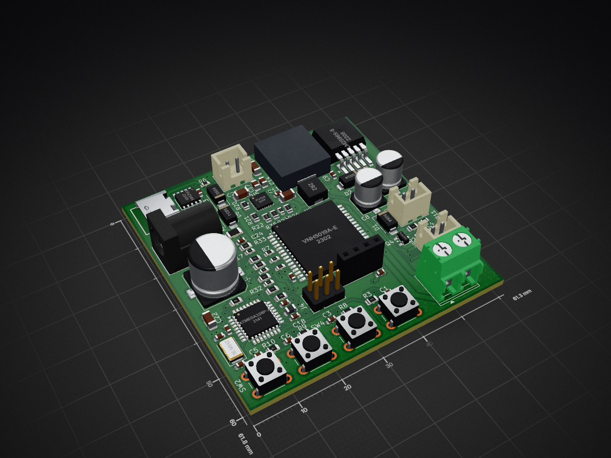
Bio thing is an open-source printed circuit board by noahalam77-code, from the noahalam77-code/TheraPatch repository on GitHub, published under the MIT licence. It is a 4-layer board of 61.3 × 61.7 mm with 82 parts on 79 nets, routed with 653 tracks and 87 vias.
It is built around the ATMEGA328P-AU, CH224K and LM2596S-5.0, with the IP2326, SS54 and AO3400A among its other parts. Its parts include 30 resistors, 25 capacitors, 7 connectors, 5 ICs and 4 diodes. It belongs with the AVR (ATmega, ATtiny) boards of this library.


TheraPatch is a handheld therapeutic device designed to help mitigate the effects of injuries such as bruises, sprains, minor cuts, and more. By using a reverse-polarity system via an H-bridge, TheraPatch can heat the affected area (dilating blood vessels) or cool it (constricting blood vessels), both of which have been shown to help with injury healing at certain temperatures (which TheraPatch can achieve).
I created TheraPatch with the primary motivation of helping people with common sports/activty related injuries while maintaining an efficient device to do so. Most of the time, when you have a bruise or scrape, you'd rely on disposable ice packs or inefficient heating pads, which are wasteful and time-consuming for long-term use. TheraPatch offers an effective, infinitely reusable solution to this. Instead of freezing water for 3-4 hours or boiling a heatpack everytime you need to reuse it, all you do with TheraPatch is plug and play. It's effective for athletes and normal people.
To use the TheraPatch, first ensure your battery/wall adapter is plugged in. Then locate the 4 buttons on the top of the device; these buttons will allow you to set your desired parameters by moving through the menus: mode (hot/cold), set temp, and set time. After your desired settings are set, click the start button to initiate your therapy session, and place the side with the Peltier facing out against the affected area
The TheraPatch looks like a simple black-and-white hot-cold block, but its guts are far more advanced. In electronics, generating heat is relatively simple. Electrons bump into each other rapidly in the wire, vibrating and thus creating the heat we feel. This is the easy part; cooling is the real engineering challenge. To cool it, I used a Peltier module, which transfers heat from one side to the other. Now, this needs to be driven by a heatsink and a fan to effectively cool. To achieve heating and cooling on the same side, I used an H bridge. The H-bridge module reverses the polarity in a Peltier module, meaning that when one side is positive and the other is negative, it cools; vice versa. All of this is controlled by a custom 4-layer PCB I designed in KiCad, with an ATmega328P as my microcontroller. The firmware reads a thermistor pressed against the Peltier plate and uses a bang-bang controller to turn the Peltier on/off to reach the desired temperature. This is all run by a rechargeable 12V battery, which charges via USB-C or a 12V wall adapter. These components are combined in a logical order in a CAD-designed box with a hole for all the input plugs and vent fans for air circulation.
Here are images of my project
| Item | Quantity | Unit price | Total price | Descrption | Link |
|---|---|---|---|---|---|
| Fan | 1 | 4.81 | 4.81 | Facliate heaitng & cooling | Link |
| Peltier | 1 | 3.90$ | $3.90 | Cool and heat | Link |
| Heatsink | 2 | 4.80$ | $9.79 | Disspate heat | Link |
| LCD screen | 1 | 0.9900$ | 0.9900$ | Displaying modes | Link |
| Thermistor | 1 | 0.9500$ | 0.9500$ | Temp meauring | Link |
| Battery | 1 | 26.99$ | $26.99 | Used as main source of power (for moblity) BMS confirmed | Link |
| Wire | 1 | 2.2300$ | 2.23$ | Battery caddy, peliter and fan extesion | Link |
| Wall adapter | 1 | $1.28 | $1.28 | 2nd way of recving power (1st battery) | Link |
| M2 screw 8mm | 100 | 0.0100$ | $1.35 | screws for battery caddy | Link |
| M2 screw 14mm | 100 | 0.0100$ | $1.35 | screws for main case | Link |
| Dupont connectors | 40 | 0.0253$ | 1.01$ | connectors for LCD and ISP proggarmer | Link |
| ISP porgrammer | 1 | 1.9100$ | $1.91 | Flashes code onto the ATMega chip | Link |
| Buttons | 20 | 0.1095$ | 2.19$ | Switching between menus & 0start/stop | Link |
| Terminal Block | 5 | 0.0864$ | 0.4300$ | For conencting things without JST conenctor | Link |
| Barrel Jack | 5 | 0.1462$ | $0.73 | Wall power input | Link |
| JST female | 20 | 0.0403$ | 0.81$ | Battery inpt | Link |
| 4 Pin connector for LCD | 10 | 0.0807$ | 0.81$ | LCD input | Link |
| Arundio flash input | 5 | 0.2238$ | 1.12$ | Pins to flash code | Link |
| USB-C | 5 | $0.1857 | $0.93 | Charging | Link |
| 5A fuse | 10 | 0.0506$ | $0.51 | PCB | Link |
| 16 Mhz cyrstal | 5 | 0.2372$ | $1.19 | PCB | Link |
| Ferrite Bead | 10 | 0.0262$ | $0.26 | PCB | Link |
| AO3400A | 5 | 0.0846$ | $0.42 | diode for the fan | Link |
| SS54 Diode | 10 | 0.0366$ | 0.3700$ | Diode used in buck and input pwr | Link |
| 33uH buck Inductor | 5 | 0.2204$ | 1.10$ | PCB | Link |
| 2.2uH boost Inductor | 5 | 0.1161$ | $0.58 | PCB | Link |
| 120K resistor | 100 | $0.0022 | $0.22 | PCB | Link |
| 90K resitor | 10 | $0.0654 | $0.65 | PCB | Link |
| 68K resistor | 100 | $0.0021 | $0.21 | PCB | Link |
| 51k resistor | 100 | $0.0021 | $0.21 | PCB | Link |
| 47K resistor | 100 | $0.0021 | $0.21 | PCB | Link |
| 10K resistor | 100 | $0.0020 | $0.20 | PCB | Link |
| 5.1K resistor | 100 | $0.00 | $0.27 | PCB | Link |
| 3.3K resistor | 100 | $0.0020 | $0.20 | PCB | Link |
| 1k resistor | 100 | $0.0076 | $0.76 | PCB | Link |
| 100Ω resistor | 100 | $0.0014 | $0.14 | PCB | Link |
| 470uF capacitor | 5 | $0.0875 | $0.44 | PCB | Link |
| 220uF capacitor | 10 | $0.0276 | $0.28 | PCB | Link |
| 100uF capacitor | 20 | $0.0372 | $0.74 | PCB | Link |
| 22uF capacitor | 20 | $0.0349 | $0.70 | PCB | Link |
| 10uF capacitor | 10 | $0.0394 | $0.39 | PCB | Link |
| 1uF capacitor | 50 | $0.0069 | $0.35 | PCB | Link |
| 0.1uF capacitor | 100 | $0.004 | $0.40 | PCB | Link |
| 22pF capacitor | 100 | $0.0041 | $0.41 | PCB | Link |
| ST VNH5019ATR-E | 1 | 9.36$ | 9.36$ | H-bridge to switch polairty | Link |
| LM2596S-5.0 | 1 | 1.42$ | 1.37$ | Buck convetor for non 12V parts | Link |
| WCH CH224K | 1 | $0.61 | $0.61 | Power negogatior, Requests 9V | Link |
| IP2326 | 1 | $0.62 | $0.62 | Boost converter for charging 9V to 12.6V | Link |
| ATMEGA328P-AU | 1 | $2.65 | $2.65 | Microcontroller | Link |
| Comment | Designator | Footprint | LCSC Part Number |
|---|---|---|---|
| USB-C | USBC1 | USBC_U:USB-C_SMD-TYPE-C-31-M-12_1 | C165948 |
| 5A Fuse | F2 | Fuse:Fuse_1206_3216Metric | C41367229 |
| Crystal | Y1 | Crystal:Crystal_SMD_5032-2Pin_5.0x3.2mm | C122519 |
| Ferrite bead | FB1 | Inductor_SMD:L_0805_2012Metric | C21519 |
| AO3400A diode | Q4 | Package_TO_SOT_SMD:SOT-23 | C20917 |
| SS54 Diode | D1, D2, D3, D6 | Diode_SMD:D_SMA | C22452 |
| 33µH inductor | L1 | inductor_33uh:IND-SMD_L12.3-W12.3 | C9400 |
| 120K Resitor | R21, R35 | Resistor_SMD:R_0805_2012Metric | C2907223 |
| 90K Resitor | R24 | Resistor_SMD:R_0805_2012Metric | C5123603 |
| 68K Resitor | R22 | Resistor_SMD:R_0805_2012Metric | C2907283 |
| 51K Resitor | R20 | Resistor_SMD:R_0805_2012Metric | C2933461 |
| 47K restior | R27 | Resistor_SMD:R_0805_2012Metric | C2930202 |
| 10K Restior | R34, R33, R28, R16, R13, R12, R10, R9, R8, R5, R3, R2, R1 | Resistor_SMD:R_0805_2012Metric | C2907219 |
| 5.1K resistor | R18, R19 | Resistor_SMD:R_0805_2012Metric | C27834 |
| 3.3K resistor | R7, R14 | Resistor_SMD:R_0603_1608Metric | C2907023 |
| 1k resistor | R32, R23, R17, R15, R6, R4 | Resistor_SMD:R_0603_1608Metric | C2907002 |
| 100Ω resistor | R11 | Resistor_SMD:R_0603_1608Metric | C105588 |
| 220uF capacitor | C2 | Capacitor_SMD:CP_Elec_6.3x7.7 | C22388075 |
| 100uF capacitor | C8 | Capacitor_SMD:CP_Elec_6.3x7.7 | C970685 |
| 22uF capacitor | C14, C17 | Capacitor_SMD:C_0805_2012Metric | C45783 |
| 10uF capacitor | C25, C23, C22,C10 | Capacitor_SMD:C_1206_3216Metric | C9807 |
| 1uF capacitor | C7 | Capacitor_SMD:C_0603_1608Metric | C29936 |
| 0.1uF capacitor | C24, C19, C18, C15, C13, C12, C11, C9, C6, C5, C4, C3, C1 | Capacitor_SMD:C_0603_1608Metric | C1590 |
| 22pF capacitor | C20,C21 | Capacitor_SMD:C_0603_1608Metric | C1653 |
| ST VNH5019ATR-E | U2 | Package_SO:ST_MultiPowerSO-30 | C2653552 |
| LM2596S-5.0 | U1 | Package_TO_SOT_SMD:TO-263-5_TabPin3 | C116713 |
| WCH CH224K | U3 | CH224K:ESSOP-10_L4.9-W3.9-P1.0-LS6.0-TL-EP | C970725 |
| IP2326 | U5 | Package_DFN_QFN:QFN-24-1EP_4x4mm_P0.5mm_EP2.6x2.6mm | C2832094 |
| ATMEGA328P-AU | U4 | Package_QFP:TQFP-32_7x7mm_P0.8mm | C14877 |
| Qty | Value | Footprint | References |
|---|---|---|---|
| 13 | 10K | Resistor_SMD:R_0805_2012Metric | R1, R2, R3, R5, R8, R9, R10, R12, R13, R16, R28, R33, R34 |
| 8 | 0.1µF | Capacitor_SMD:C_0603_1608Metric | C1, C3, C4, C5, C6, C9, C12, C15 |
| 6 | 1K | Resistor_SMD:R_0603_1608Metric | R4, R6, R15, R17, R23, R32 |
| 5 | 0.1uF | Capacitor_SMD:C_0603_1608Metric | C11, C13, C18, C19, C24 |
| 4 | 10uF | Capacitor_SMD:C_1206_3216Metric | C10, C22, C23, C25 |
| 4 | SS54 | Diode_SMD:D_SMA | D1, D2, D3, D6 |
| 2 | 120K | Resistor_SMD:R_0805_2012Metric | R21, R35 |
| 2 | 22pF | Capacitor_SMD:C_0603_1608Metric | C20, C21 |
| 2 | 22uF | Capacitor_SMD:C_0805_2012Metric | C14, C17 |
| 2 | 3.3K | Resistor_SMD:R_0603_1608Metric | R7, R14 |
| 2 | 5.1K | Resistor_SMD:R_0805_2012Metric | R18, R19 |
| 1 | 100R | Resistor_SMD:R_0603_1608Metric | R11 |
| 1 | 100µF | Capacitor_SMD:CP_Elec_6.3x7.7 | C8 |
| 1 | 16 MHz | Crystal:Crystal_SMD_5032-2Pin_5.0x3.2mm | Y1 |
| 1 | 1uF | Capacitor_SMD:C_0603_1608Metric | C7 |
| 1 | 2.2uH | Inductor_SMD:L_Sunlord_MWSA0503S | L2 |
| 1 | 220µF | Capacitor_SMD:CP_Elec_6.3x7.7 | C2 |
| 1 | 33uH 3A | inductor_33uh:IND-SMD_L12.3-W12.3 | L1 |
| 1 | 470µF | Capacitor_SMD:CP_Elec_10x10.5 | C16 |
| 1 | 47K | Resistor_SMD:R_0805_2012Metric | R27 |
| 1 | 51K | Resistor_SMD:R_0805_2012Metric | R20 |
| 1 | 5A | Fuse:Fuse_1206_3216Metric | F2 |
| 1 | 68K | Resistor_SMD:R_0805_2012Metric | R22 |
| 1 | 90K | Resistor_SMD:R_0805_2012Metric | R24 |
| 1 | AO3400A | Package_TO_SOT_SMD:SOT-23 | Q4 |
| 1 | ATmega328P-A | Package_QFP:TQFP-32_7x7mm_P0.8mm | U4 |
| 1 | Back Button | Button_Switch_THT:SW_PUSH_6mm_H4.3mm | SW4 |
| 1 | Barrel_Jack | Barrel_JJack:Barrel_JJack | J1 |
| 1 | Bat | Connector_JST:JST_XH_B2B-XH-A_1x02_P2.50mm_Vertical | J7 |
| 1 | CH224K | CH224K:ESSOP-10_L4.9-W3.9-P1.0-LS6.0-TL-EP | U3 |
| 1 | Coder | Connector_PinHeader_2.54mm:PinHeader_2x03_P2.54mm_Vertical | J4 |
| 1 | FerriteBead | Inductor_SMD:L_0805_2012Metric | FB1 |
| 1 | IP2326 | Package_DFN_QFN:QFN-24-1EP_4x4mm_P0.5mm_EP2.6x2.6mm | U5 |
| 1 | LCD display | Connector_PinSocket_2.54mm:PinSocket_1x04_P2.54mm_Vertical | J6 |
| 1 | LM2596S-5 | Package_TO_SOT_SMD:TO-263-5_TabPin3 | U1 |
| 1 | Left Button | Button_Switch_THT:SW_PUSH_6mm_H4.3mm | SW2 |
| 1 | Peliter | TerminalBlock_Phoenix:TerminalBlock_Phoenix_PT-1,5-2-5.0-H_1x02_P5.00mm_Horizontal | J2 |
| 1 | Right Button | Button_Switch_THT:SW_PUSH_6mm_H4.3mm | SW5 |
| 1 | Start/Stop | Button_Switch_THT:SW_PUSH_6mm_H4.3mm | SW3 |
| 1 | TYPE-C-31-M-12 | USBC_U:USB-C_SMD-TYPE-C-31-M-12_1 | USBC1 |
| 1 | VNH5019A-E | Package_SO:ST_MultiPowerSO-30 | U2 |
| 1 | fan | Connector_JST:JST_XH_B2B-XH-A_1x02_P2.50mm_Vertical | J5 |
| 1 | themrisotorr | Connector_JST:JST_XH_B2B-XH-A_1x02_P2.50mm_Vertical | J9 |
It measures 61.3 × 61.7 mm and has 4 copper layers, 1.6 mm thick.
82 parts, built around the ATMEGA328P-AU, CH224K, LM2596S-5.0 and IP2326. The full list of its parts is on this page, with links to each part's symbol and footprint where PCBKit's library has them.
From the noahalam77-code/TheraPatch repository on GitHub, at the commit this page was made from: the board is PCB/Bio_thing.kicad_pcb and its schematic PCB/Bio_thing.kicad_sch. PCBKit opens the board in the browser, with nothing to install.
Its repository publishes it under the MIT licence: you may reuse it on that licence's terms (keep the author's notice, and for a copyleft licence share your changes alike).
NgxLuis/30W-PD-Power-Bank
PCB design - 30W High-Performance Power Bank utilizing SW3518, IP2326, and BM3451 for a 3S 21700 battery pack.

JulCesarCorrea/Basic-EPS
PCB design para a 4 fase da obsat

Prajwal-sahyadri-ECE/-Optimized-Powersupply-design-
A highly detailed PCB to maintain an power supply for a defined hardware architecture specifically for ICS system

rmalchow/ondaire
A KiCad 10 project for a powered-speaker node: an ESP32-S3 dev board drops into a socket, an I²S DAC + class-D amp turn the stream into 40–50 W of audio, and the whole thing runs from a single USB-C cable via USB-PD.

jlcjak/astra_piNas
Six-layer CM5 Lite dual-NVMe carrier with PCIe switch, Ethernet, microSD, USB-C PD and PoE. Review design; fabrication hold documented.

ut-ras/chessbot
Python/MQTT software, Raspberry Pi Config files, PCB Schematics for an autonomous chess playing robot


DEV-ajthedj/Keyboard
A custom RGB keyboard that features three 1D capacitive touch sliders, two joysticks, an OLED screen, a fingerprint sensor, and plenty of macro keys!