Skip to the content
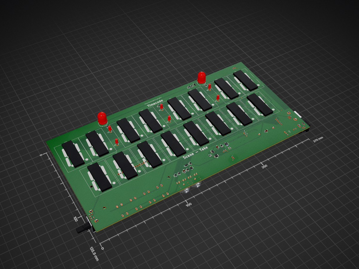
2 layers270 × 135.9 mmDigiSlatePlus, the printed circuit board in 3D

The project is in an early developement state.

Size
270 × 135.9 mm
Copper layers
2
Thickness
1.6 mm
Parts
122
Nets
123
Pads
584
Tracks, vias
1,633, 105
Pours
2
Routed
Yes
KiCad
KiCad 8.0 (file 20240108)
Created
6 Aug 2024
Updated
29 Aug 2024

Overview

DigiSlatePlus is an open-source printed circuit board by nibble-arts, from the nibble-arts/DigiSlatePlus repository on GitHub. It is a 2-layer board of 270 × 135.9 mm with 122 parts on 123 nets, routed with 1,633 tracks and 105 vias.

It is built around the ESP32-S3-WROOM-1-N8, MAX7219M and LM2596S-ADJ, with the DS3231MZ+, DW01A and TP4056 among its other parts. Its parts include 34 resistors, 25 ICs, 21 capacitors, 14 diodes and 10 connectors. It belongs with the ESP32 boards of this library.

Main components

11

README

README.md

DigiSlate+

The project is in an early developement state.

DigiSlate+ is inspired from the DigiSlate and the DIY timecode generator from mitkunz. The aim for the DigiSlate+ is not only to be able to read and display timecode, but also to generate it itself. To make this possible, the hardware is extended by a real time clock with high running accuracy. The RTC module DS3231 with temperature-compensated quartz offers the possibility.

The DigiSlate+ has two operating states. If an external time code is fed in and the slate is switched on, it starts in read mode. The time code is read, shown on the LED display and the time in the RTC is updated. The DS3231 sends an interrupt to the controller at the beginning of each second. The offset of frames to the time code fed in is stored in the EEPROM memory in order to provide a frame-accurate time in free-running mode.

As soon as the external time code is disconnected or the slate is switched on without a time code at the input, it changes to free-running mode. It now runs automatically with the time from the RTC and the saved frame offset. The accuracy of the RTC module allows a deviation of 1 frame in 8 hours.

A socond row of 7-segment LEDs display the scene and take numbers.

Parts

122
QtyValueFootprintReferences
16SA15-11SRWA7-segment-led:FYS-12011AU3, U4, U5, U6, U8, U9, U10, U11, U12, U13, U14, U15, U17, U18, U19, U20
1210KResistor_SMD:R_1206_3216MetricR1, R2, R3, R4, R12, R16, R26, R27, R28, R29, R30, R32
9100nF/50VCapacitor_SMD:C_1206_3216Metric_Pad1.33x1.80mm_HandSolderC1, C2, C3, C4, C6, C12, C15, C19, C21
6100Resistor_SMD:R_1206_3216MetricR11, R13, R14, R15, R17, R31
6LEDLED_THT:LED_D3.0mm_FlatTopD1, D2, D3, D4, D5, D6
41Button_Switch_THT:SW_PUSH-12mmSW2, SW3, SW4, SW5
410nF/50VCapacitor_SMD:C_1206_3216Metric_Pad1.33x1.80mm_HandSolderC8, C10, C13, C17
4470RResistor_SMD:R_1206_3216MetricR7, R8, R9, R10
3180Resistor_SMD:R_0805_2012Metric_Pad1.20x1.40mm_HandSolderR23, R24, R25
31KResistor_SMD:R_0805_2012Metric_Pad1.20x1.40mm_HandSolderR18, R19, R21
320KPotentiometer_SMD:Potentiometer_Vishay_TS53YL_VerticalRV1, RV2, RV3
32N2222Package_TO_SOT_SMD:SOT-23Q1, Q2, Q4
2100uF/10VCapacitor_Tantalum_SMD:CP_EIA-7343-31_Kemet-D_Pad2.25x2.55mm_HandSolderC14, C18
2220uF/10VCapacitor_Tantalum_SMD:CP_EIA-7343-31_Kemet-D_Pad2.25x2.55mm_HandSolderC16, C20
2220uF/25VCapacitor_Tantalum_SMD:CP_EIA-7343-31_Kemet-D_Pad2.25x2.55mm_HandSolderC9, C11
2470uF/10VCapacitor_Tantalum_SMD:CP_EIA-7343-31_Kemet-D_Pad2.25x2.55mm_HandSolderC5, C7
24K7Resistor_SMD:R_1206_3216MetricR5, R6
2LEDLED_THT:LED_D10.0mmD7, D8
2MAX7219Package_SO:SOIC-24W_7.5x15.4mm_P1.27mmU7, U16
2MainsConnector_JST:JST_XH_B2B-XH-AM_1x02_P2.50mm_VerticalJ5, J6
1+8-24 VoltConnector_BarrelJack:BarrelJack_GCT_DCJ200-10-A_HorizontalJ3
110KPotentiometer_THT:Potentiometer_Bourns_3296W_VerticalRV4
11K2Resistor_SMD:R_0805_2012Metric_Pad1.20x1.40mm_HandSolderR22
11K8Resistor_SMD:R_1206_3216MetricR33
11N4148Diode_SMD:D_PowerDI-123D14
1360RResistor_SMD:R_1206_3216MetricR20
13V3LED_SMD:LED_0603_1608MetricD13
15K6Resistor_SMD:R_1206_3216MetricR34
15VLED_SMD:LED_0603_1608MetricD12
168uHInductor_SMD:L_7.3x7.3_H3.5L1
1BOOTButton_Switch_SMD:SW_Push_SPST_NO_Alps_SKRKSW6
1BatteryConnector_JST:JST_XH_B2B-XH-AM_1x02_P2.50mm_VerticalJ4
1Battery_CellBattery:BatteryHolder_ComfortableElectronic_CH273-2450_1x2450BT1
1DS3231MPackage_SO:SOIC-16W_7.5x10.3mm_P1.27mmU2
1DW01APackage_TO_SOT_SMD:SOT-23-6U22
1ESP32-S3-WROOM-1RF_Module:ESP32-S3-WROOM-1U1
1EXTLED_THT:LED_D3.0mmD11
1FS8205APackage_SO:TSSOP-8_3x3mm_P0.65mmQ3
1IO7Connector_PinHeader_1.00mm:PinHeader_1x01_P1.00mm_VerticalJ10
1KA78M05_TO252Package_TO_SOT_SMD:TO-252-2U24
1LD1117S33TR_SOT223Package_TO_SOT_SMD:SOT-223-3_TabPin2U25
1LED_Dual_KAKLED_THT:LED_D3.0mm-3D9
1LM2596S-ADJPackage_TO_SOT_SMD:TO-263-5_TabPin6U21
1LOGOLogos:Open-Source-Hardware-LogoG***
1MISOConnector_PinHeader_1.00mm:PinHeader_1x01_P1.00mm_VerticalJ9
1RotaryEncoder-SWRotary_Encoder:RotaryEncoder_Bourns_Horizontal_PEC12R-2x17F-SxxxxSW1
1SS310Diode_SMD:D_SMAD10
1SerialConnector_JST:JST_XH_B5B-XH-AM_1x05_P2.50mm_VerticalJ1
1TP4056TP4056:TP4056-42-ESOP8_TPWU23
1Timecode INConnector_Audio:Jack_3.5mm_CUI_SJ1-3525N_HorizontalJ7
1Timecode OUTConnector_Audio:Jack_3.5mm_CUI_SJ1-3525N_HorizontalJ8
1USB_BConnector_USB:USB_B_Lumberg_2411_02_HorizontalJ2
1WC1602ADisplay:WC1602ADS1

Similar boards

  • 2 layers270 × 140 mmDigiSlatePlus, the printed circuit board in 3D

    DigiSlatePlus

    digislateplus/digislateplus.github.io

    DigiSlate+ is based on the DigiSlate and is inspired by the DIY timecode generator from mitkunz. The aim for the DigiSlate+ is not only to be able to read and display timecode, but also to generate it itself.

    130 parts
  • 2 layers66 × 58.4 mmCC SSD 02, the printed circuit board in 3D

    CC SSD 02

    attachix/ukit-pcb

    The PCBs needed to create the U:Kit sensor kit.

    42 parts1
  • 2 layers96.5 × 73.2 mmBt radio manager e01, the printed circuit board in 3D

    Bt radio manager e01

    marianobilli/bluetooth-radio-manager

    A self-contained, battery-powered box that puts four 2.4 GHz radios under one ESP32-S3, with a small OLED and encoder UI, in a 3D-printed case.

    32 parts
  • 2 layers100 × 80 mmLayouts, the printed circuit board in 3D

    Layouts

    jamesburton/Lolin32OLEDLaserTagTest

    Reverse-engineering, decoding, and transmitting Vatos infrared laser-tag signals across two ESP32 boards:

    38 parts1
  • 2 layers162.6 × 147.3 mmEnAcess PCB, the printed circuit board in 3D

    EnAcess PCB

    jumarubea/OpenSmartMeter

    Low-cost & OEM agnostic GSM prepaid smart energy meter with a customizable API.

    153 partsMIT
  • 4 layers95 × 76.2 mmDeWille Control, the printed circuit board in 3D

    DeWille Control

    zmeiresearch/DeWille

    A high-performance DIY audio DAC

    171 parts23
  • 4 layers78.5 × 91 mmFuSa1, the printed circuit board in 3D

    FuSa1

    engrtech/STM32_RC01_PCB

    PCB on KiKad 9

    119 parts1
  • 2 layers88.9 × 89.9 mmLi ion backup, the printed circuit board in 3D

    Li ion backup

    Gosmann/Li-ion-UPS-24V

    24V-input 24V-out lithium ion backup board

    101 parts

Questions

How big is the DigiSlatePlus PCB?

It measures 270 × 135.9 mm and has 2 copper layers, 1.6 mm thick.

What parts does the DigiSlatePlus use?

122 parts, built around the ESP32-S3-WROOM-1-N8, MAX7219M, LM2596S-ADJ and DS3231MZ+. The full list of its parts is on this page, with links to each part's symbol and footprint where PCBKit's library has them.

Where can I download the DigiSlatePlus KiCad files?

From the nibble-arts/DigiSlatePlus repository on GitHub, at the commit this page was made from: the board is hardware/PCB/DigiSlatePlus.kicad_pcb and its schematic hardware/PCB/DigiSlatePlus-Power.kicad_sch. PCBKit opens the board in the browser, with nothing to install.

Can I use the DigiSlatePlus design in my own project?

Its repository states no licence, so its author keeps all rights: ask nibble-arts before reusing the design.