Skip to the content
2 layers110 × 84 mmPKE, the printed circuit board in 3D

Final project - ESP32-S3 based PKE system for vehicle access and ignition

Size
110 × 84 mm
Copper layers
2
Thickness
1.6 mm
Parts
90
Nets
98
Pads
278
Tracks, vias
360, 262
Pours
2
Routed
Yes
KiCad
KiCad 9.0 (file 20241229)
Created
25 Mar 2026
Updated
25 Mar 2026

Overview

PKE is an open-source printed circuit board by neriyashalom, from the neriyashalom/PKE-Car-System repository on GitHub. It is a 2-layer board of 110 × 84 mm with 90 parts on 98 nets, routed with 360 tracks and 262 vias.

It is built around the ESP32-S3-DEVKITC-1-N8, 2N2222A and CMA51H-S-DC12V-C, with the 1N4728A, P6KE18A and SR560 among its other parts. Its parts include 35 resistors, 17 diodes, 10 transistors, 9 switches and 7 capacitors. It belongs with the ESP32 boards of this library.

Main components

6

README

README.md

PKE-Car-System

ESP32-S3 Based PKE System for Vehicle Access and Ignition

Project Overview

This project presents the design and implementation of a Passive Keyless Entry (PKE) system for a vehicle, based on the ESP32-S3 microcontroller.
The system enables keyless door locking and unlocking, mirror folding and unfolding, and vehicle ignition control through a Start-Stop push button, using BLE proximity detection.

The project combines hardware, firmware, PCB design, and practical testing into a complete embedded automotive-oriented solution.
A dedicated PCB was designed to integrate the ESP32-S3 controller, protection circuits, input conditioning stages, relay drivers, and relay blocks required for interfacing with the vehicle.

In addition to the PKE functionality, the system was designed to operate alongside the original vehicle key without interfering with its normal operation.

System Architecture

The system is built around the following main blocks:

  • ESP32-S3 controller
  • BLE-based proximity detection
  • Start-Stop push button interface
  • Vehicle input conditioning circuits
  • Protection and voltage level adaptation circuits
  • Relay drivers and relay blocks
  • Dedicated custom PCB
  • Power management and DC-DC conversion

Main Inputs

  • BLE tag for proximity detection
  • Brake pedal signal
  • Handbrake signal
  • Door status signal
  • Ignition status signal
  • Start-Stop button feedback

Main Outputs

  • Door lock control
  • Door unlock control
  • Mirror fold and unfold control
  • ACC control
  • IGN control
  • START control
  • Turn signal indication outputs
  • Start-Stop button LED control

Key Features

  • Passive keyless vehicle access using BLE proximity detection
  • Start-Stop ignition control based on defined safety conditions
  • Support for vehicle functions such as mirrors, blinkers, and ignition lines
  • Dedicated PCB for structured and reliable hardware integration
  • State-based firmware logic for clear and predictable system behavior
  • Practical implementation and testing on prototype and final PCB
  • Compatibility with the original vehicle key system

Repository Structure

  • Code/ - source code for the ESP32-S3 based PKE controller
  • KICAD/ - schematic and PCB design files created in KiCad
  • Multisim/ - simulation files used during the design and verification stages
  • ESP32S3.jpg - image of the implemented ESP32-S3 based hardware
  • Final Project.pdf - final project documentation and report
  • README.md - general description of the project and repository contents

Tools and Technologies

  • Microcontroller: ESP32-S3
  • Firmware: Arduino IDE, C/C++
  • PCB Design: KiCad
  • Simulation: Multisim
  • Communication: BLE
  • Hardware: Relay drivers, relays, protection circuits, DC-DC converter
  • Application Domain: Embedded systems, automotive electronics

Project Outcome

The project demonstrates a complete embedded hardware-software solution for implementing a custom PKE system in a vehicle environment.
It includes concept definition, hardware design, PCB implementation, firmware development, simulation, prototype testing, and final integration.

Author

Final project in Electrical and Electronics Engineering
Developer: Neriya Shalom
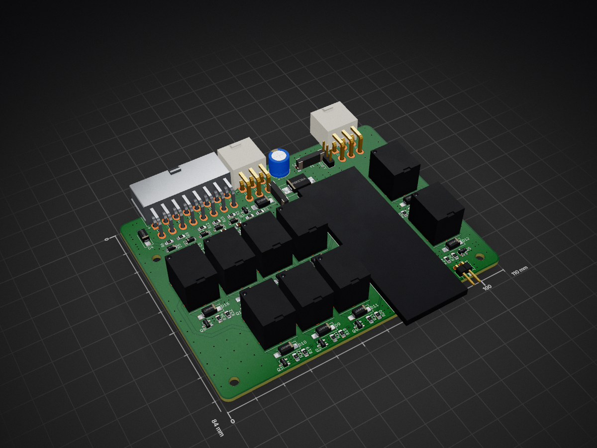
Parts

90
QtyValueFootprintReferences
151kResistor_SMD:R_0805_2012Metric_Pad1.20x1.40mm_HandSolderR1, R2, R7, R10, R13, R16, R18, R19, R20, R24, R25, R28, R29, R32, R33
10100kResistor_SMD:R_0805_2012Metric_Pad1.20x1.40mm_HandSolderR4, R21, R22, R23, R26, R27, R30, R31, R34, R35
101N4007Diode_SMD:D_SMA_HandsolderingD4, D9, D10, D11, D12, D13, D14, D15, D16, D17
102N2222APackage_TO_SOT_SMD:SOT-23-3Q1, Q2, Q3, Q4, Q5, Q6, Q7, Q8, Q9, Q10
9CMA51H-S-DC12V-CCMA51H_RELAY:CMA51HSDC12VCK1, K2, K3, K4, K5, K6, K7, K8, K9
6100nCapacitor_SMD:C_0805_2012Metric_Pad1.18x1.45mm_HandSolderC1, C3, C4, C5, C6, C7
51N4728ADiode_SMD:D_SOD-123D3, D5, D6, D7, D8
4MountingHoleMountingHole:MountingHole_3.2mm_M3H1, H2, H3, H4
310kResistor_SMD:R_0805_2012Metric_Pad1.20x1.40mm_HandSolderR5, R8, R17
330kResistor_SMD:R_0805_2012Metric_Pad1.20x1.40mm_HandSolderR3, R6, R15
24.7kResistor_SMD:R_0805_2012Metric_Pad1.20x1.40mm_HandSolderR9, R12
247kResistor_SMD:R_0805_2012Metric_Pad1.20x1.40mm_HandSolderR11, R14
2Conn_01x06Connector_Molex:Molex_Mini-Fit_Jr_5569-06A2_2x03_P4.20mm_HorizontalJ1, J3
150V220uCapacitor_THT:CP_Radial_D8.0mm_P3.50mmC2
1Conn_01x02Connector_PinHeader_2.54mm:PinHeader_1x02_P2.54mm_HorizontalJ_RST1
1Conn_01x03Connector_PinHeader_2.54mm:PinHeader_1x03_P2.54mm_VerticalJ_DCDC1
1Conn_01x14Connector_Molex:Molex_Mini-Fit_Jr_5569-16A2_2x08_P4.20mm_HorizontalJ2
1ESP32_S3_DevKitCESP32-S3-DevKitC-1-N32R16V:ESP32S3DevKitC1N32R16VESP32_S3_DevKitC_1
1FUSE_COILS 1.1AFuse:Fuse_1812_4532Metric_Pad1.30x3.40mm_HandSolderF2
1FUSE_DCDC 1.1AFuse:Fuse_1812_4532Metric_Pad1.30x3.40mm_HandSolderF1
1P6KE18ADiode_SMD:D_SMC_HandsolderingD2
1SR560Diode_SMD:D_SMB_HandsolderingD1

Similar boards

  • 2 layers92 × 70 mmTexecom power reset, the printed circuit board in 3D

    Texecom power reset

    jd710313/texecom-power-reset

    A single board with an ESP32-C3 (Tasmota) and two on-board relays. It sits inside a Texecom Premier Elite 64-W housing and can remotely "hard power reset" the panel by briefly cutting both its battery and 16VAC feeds.

    45 parts
  • 2 layers99 × 90 mmExtron input, the printed circuit board in 3D

    Extron input

    rattboi/extron-scart-adapter

    Cheap adapter for (some) extron matrix switchers to allow SCART input with no cables

    22 parts37
  • 2 layers160 × 200 mmRetro programmer, the printed circuit board in 3D

    Retro programmer

    lynchaj/duodyne

    Duodyne is a hobbyist retrocomputer system designed to run ROMWBW. It is comprised of modules on a system bus

    209 parts15
  • 2 layers108 × 122 mmMyolo, the printed circuit board in 3D

    Myolo

    nico-entz/MyoloV2

    A simple muon/particle detector based on STM32 (BluePill), Scintillators and MicroFC SiPMS

    67 parts8MIT
  • 2 layers210 × 125 mmController bldc, the printed circuit board in 3D

    Controller bldc

    david8128/Electeam-Sharky

    Firmware designed in ESP32 DEVKIT microcontroller where motor, throttle, breaks, Nextion touch screen and more systems are integrated.

    73 parts2GPL-3.0
  • 4 layers284.2 × 102.8 mmFred v3, the printed circuit board in 3D

    Fred v3

    AMR-Frederico/Fred_PCB

    PCB para o Fred

    243 parts1MIT
  • 2 layers65 × 76 mmSensor Indicator, the printed circuit board in 3D

    Sensor Indicator

    finnmo/IoT-Water-Tank-Level-Monitor

    A low-cost IoT water level monitoring device designed to provide visual status indication and remote telemetry for tanks, pits, and other liquid storage applications.

    23 parts

Questions

How big is the PKE PCB?

It measures 110 × 84 mm and has 2 copper layers, 1.6 mm thick.

What parts does the PKE use?

90 parts, built around the ESP32-S3-DEVKITC-1-N8, 2N2222A, CMA51H-S-DC12V-C and 1N4728A. The full list of its parts is on this page, with links to each part's symbol and footprint where PCBKit's library has them.

Where can I download the PKE KiCad files?

From the neriyashalom/PKE-Car-System repository on GitHub, at the commit this page was made from: the board is KICAD/PKE.kicad_pcb and its schematic KICAD/PKE.kicad_sch. PCBKit opens the board in the browser, with nothing to install.

Can I use the PKE design in my own project?

Its repository states no licence, so its author keeps all rights: ask neriyashalom before reusing the design.