
4 layers67.7 × 97.2 mm

A repo on my project of making a DIY startracker for my astrophotography desires.
Orion is an open-source printed circuit board by NBER08, from the NBER08/StartrackerOrion-Hardware repository on GitHub, published under the MIT licence. It is a 2-layer board of 86.1 × 71.9 mm with 105 parts on 111 nets, routed with 848 tracks and 278 vias.
It is built around the ESP32-S3-WROOM-1-N8, XL6009 and TMC2209-LA, with the SRV05-4, TPS2121RUXR and LI0603G121R-10 among its other parts. Its parts include 37 resistors, 35 capacitors, 8 ICs, 6 connectors and 3 diodes. It belongs with the ESP32 boards of this library.


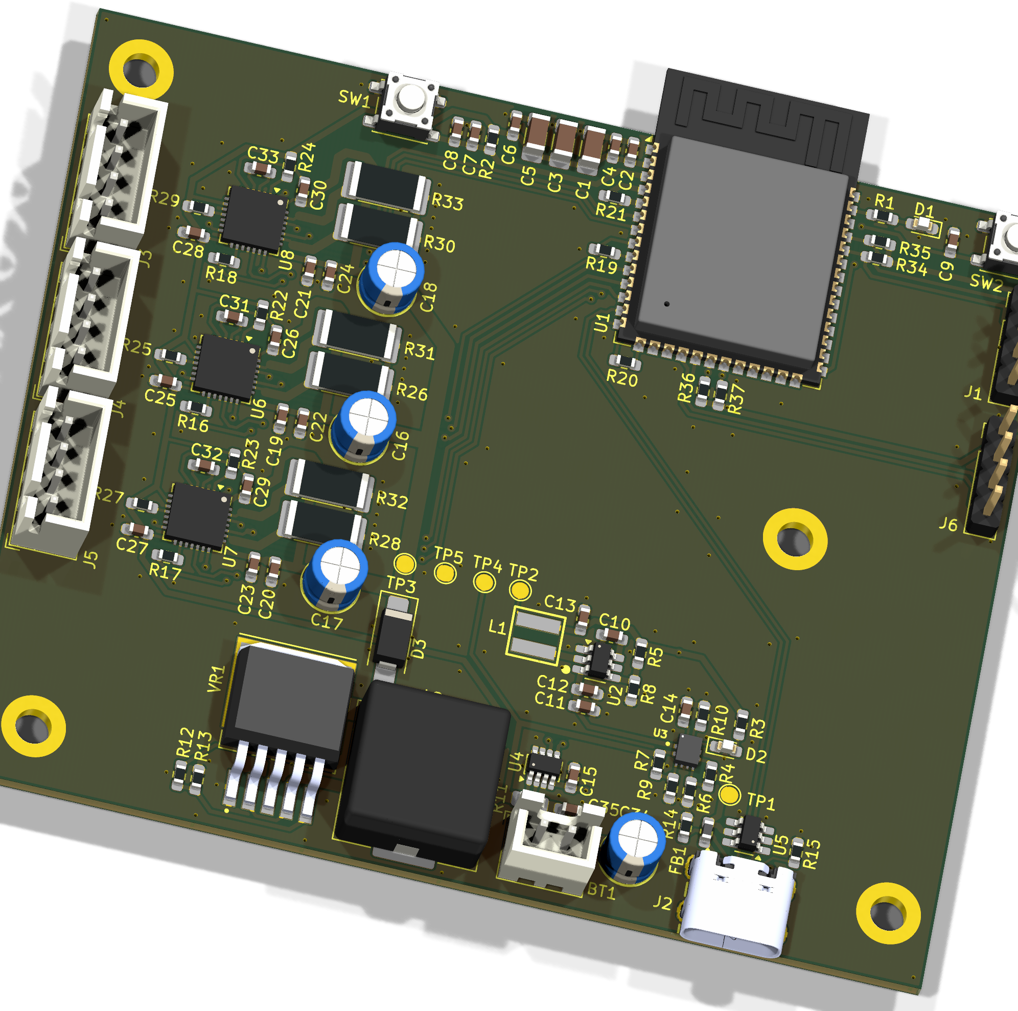
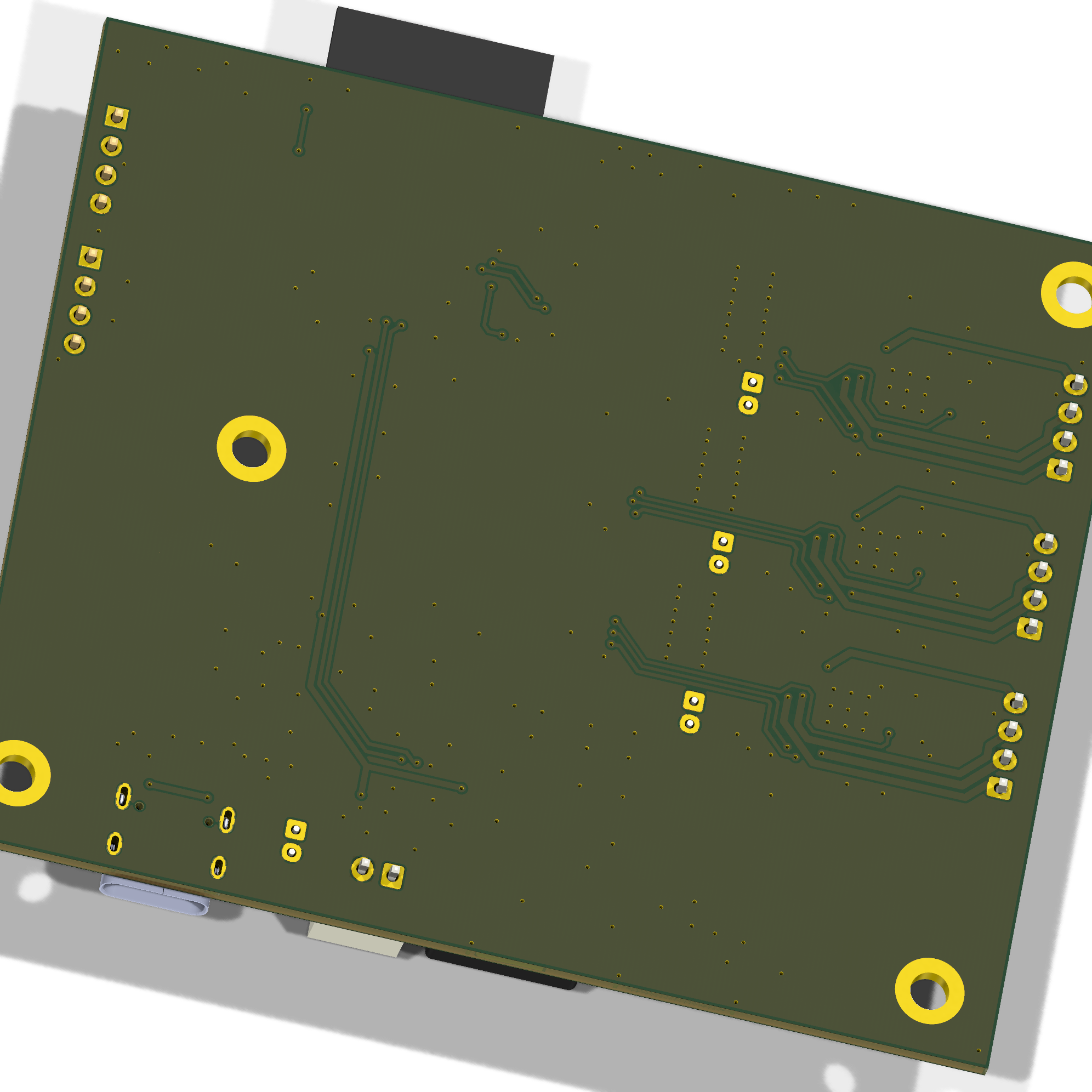
| Parameter | Value |
|---|---|
| Dimensions | 86.06 × 71.93 mm |
.
├─ Computations       # Misc calculations
├─ HTML               # HTML files for generated webpage
├─ Images             # Pictures and renders
│
├─ kibot_resources    # External resources for KiBot
│  ├─ colors          # Color theme for KiCad
│  ├─ fonts           # Fonts used in the project
│  ├─ scripts         # External scripts used with KiBot
│  └─ templates       # Templates for KiBot generated reports
│
├─ kibot_yaml         # KiBot YAML config files
├─ KiRI               # KiRI (PCB diff viewer) files
│
├─ lib                # KiCad footprint and symbol libraries
│  ├─ 3d_models       # Component 3D models
│  ├─ lib_fp          # Footprint libraries
│  └─ lib_sym         # Symbol libraries
│
├─ Logos              # Logos
│
├─ Manufacturing      # Assembly and fabrication documents
│  ├─ Assembly        # Assembly documents (BoM, pos, notes)
│ │| Qty | Value | Footprint | References |
|---|---|---|---|
| 19 | 100n | Capacitor_SMD:C_0603_1608Metric_Pad1.08x0.95mm_HandSolder | C10, C12, C15, C19, C20, C21, C22, C23, C24, C25, C26, C27, C28, C29, C30, C35 +3 |
| 7 | 10k | Resistor_SMD:R_0603_1608Metric_Pad0.98x0.95mm_HandSolder | R2, R22, R23, R24, R25, R27, R29 |
| 6 | 1k | Resistor_SMD:R_0603_1608Metric_Pad0.98x0.95mm_HandSolder | R16, R17, R18, R19, R20, R21 |
| 6 | 220m | Resistor_SMD:R_2512_6332Metric_Pad1.40x3.35mm_HandSolder | R26, R28, R30, R31, R32, R33 |
| 5 | 47k | Resistor_SMD:R_0603_1608Metric_Pad0.98x0.95mm_HandSolder | R4, R34, R35, R36, R37 |
| 4 | 100u | Capacitor_THT:CP_Radial_D5.0mm_P2.00mm | C16, C17, C18, C34 |
| 4 | MountingHole_Pad | MountingHole:MountingHole_3.2mm_M3_DIN965_Pad | H1, H2, H3, H4 |
| 3 | 100u | Capacitor_SMD:C_1206_3216Metric_Pad1.33x1.80mm_HandSolder | C1, C3, C5 |
| 3 | 22n | Capacitor_SMD:C_0603_1608Metric_Pad1.08x0.95mm_HandSolder | C31, C32, C33 |
| 3 | Conn_01x04_Pin | Connector_JST:JST_XH_B4B-XH-A_1x04_P2.50mm_Vertical | J3, J4, J5 |
| 3 | TMC2209-LA | Package_DFN_QFN:VQFN-28-1EP_5x5mm_P0.5mm_EP3.7x3.7mm | U6, U7, U8 |
| 2 | 120 | Resistor_SMD:R_0603_1608Metric_Pad0.98x0.95mm_HandSolder | R1, R3 |
| 2 | 1u | Capacitor_SMD:C_0603_1608Metric_Pad1.08x0.95mm_HandSolder | C11, C14 |
| 2 | 33k | Resistor_SMD:R_0603_1608Metric_Pad0.98x0.95mm_HandSolder | R6, R9 |
| 2 | 5k1 | Resistor_SMD:R_0603_1608Metric_Pad0.98x0.95mm_HandSolder | R14, R15 |
| 2 | Conn_01x04_Pin | Connector_PinHeader_2.54mm:PinHeader_1x04_P2.54mm_Vertical | J1, J6 |
| 2 | RED | LED_SMD:LED_0603_1608Metric_Pad1.05x0.95mm_HandSolder | D1, D2 |
| 1 | 100k | Resistor_SMD:R_0603_1608Metric_Pad0.98x0.95mm_HandSolder | R5 |
| 1 | 10m | Resistor_SMD:R_0805_2012Metric_Pad1.20x1.40mm_HandSolder | R11 |
| 1 | 10u | Capacitor_SMD:C_0603_1608Metric_Pad1.08x0.95mm_HandSolder | C7 |
| 1 | 21k5 | Resistor_SMD:R_0603_1608Metric_Pad0.98x0.95mm_HandSolder | R10 |
| 1 | 22k1 | Resistor_SMD:R_0603_1608Metric_Pad0.98x0.95mm_HandSolder | R8 |
| 1 | 22p | Capacitor_SMD:C_0603_1608Metric_Pad1.08x0.95mm_HandSolder | C2 |
| 1 | 22u | Capacitor_SMD:C_0603_1608Metric_Pad1.08x0.95mm_HandSolder | C4 |
| 1 | 2k8 | Resistor_SMD:R_0603_1608Metric_Pad0.98x0.95mm_HandSolder | R12 |
| 1 | 330 | Resistor_SMD:R_0603_1608Metric_Pad0.98x0.95mm_HandSolder | R13 |
| 1 | 3V3 | TestPoint:TestPoint_Pad_D1.5mm | TP2 |
| 1 | 47u | Inductor_SMD:L_Changjiang_FXL1365 | L2 |
| 1 | 47u | Capacitor_SMD:C_0603_1608Metric_Pad1.08x0.95mm_HandSolder | C13 |
| 1 | 5u6 | Project_Components:WE-XHMI_4040 | L1 |
| 1 | 82k | Resistor_SMD:R_0603_1608Metric_Pad0.98x0.95mm_HandSolder | R7 |
| 1 | BATT | TestPoint:TestPoint_Pad_D1.5mm | TP4 |
| 1 | BOOT | Button_Switch_SMD:SW_SPST_PTS647_Sx38 | SW2 |
| 1 | Battery | Connector_JST:JST_XH_B2B-XH-A_1x02_P2.50mm_Vertical | BT1 |
| 1 | ESP32-S3-WROOM-1 | Project_Components:ESP32-S3-WROOM-1_novias | U1 |
| 1 | GND | TestPoint:TestPoint_Pad_D1.5mm | TP5 |
| 1 | INA219BxDCN | Package_TO_SOT_SMD:SOT-23-8 | U4 |
| 1 | LI0603G121R-10 | Inductor_SMD:L_0603_1608Metric_Pad1.05x0.95mm_HandSolder | FB1 |
| 1 | LMR51420 | Package_TO_SOT_SMD:SOT-23-6_Handsoldering | U2 |
| 1 | RST | Button_Switch_SMD:SW_SPST_PTS647_Sx38 | SW1 |
| 1 | SRV05-4 | Package_TO_SOT_SMD:SOT-23-6_Handsoldering | U5 |
| 1 | SS34 | Diode_SMD:D_SMA_Handsoldering | D3 |
| 1 | TPS2121RUXR | TPS2121RUXR:IC_TPS2121RUXR | U3 |
| 1 | USB4105GFA | Project_Components:GCT_USB4105GFA | J2 |
| 1 | VBUS | TestPoint:TestPoint_Pad_D1.5mm | TP1 |
| 1 | VM | TestPoint:TestPoint_Pad_D1.5mm | TP3 |
| 1 | XL6009 | Project_Components:DPAK170P1435X465-6N | VR1 |
It measures 86.1 × 71.9 mm and has 2 copper layers, 1.66 mm thick.
105 parts, built around the ESP32-S3-WROOM-1-N8, XL6009, TMC2209-LA and SRV05-4. The full list of its parts is on this page, with links to each part's symbol and footprint where PCBKit's library has them.
From the NBER08/StartrackerOrion-Hardware repository on GitHub, at the commit this page was made from: the board is Orion.kicad_pcb and its schematic Block Diagram.kicad_sch. PCBKit opens the board in the browser, with nothing to install.
Its repository publishes it under the MIT licence: you may reuse it on that licence's terms (keep the author's notice, and for a copyleft licence share your changes alike).

NBER08/CanSat_Devboard
. ├─ Computations # Misc calculations ├─ HTML # HTML files for generated webpage ├─ Images # Pictures and renders │ ├─ kibotresources # External resources for KiBot │ ├─ colors # Color theme for KiCad │ ├─ fonts # Fonts…


NBER08/SX1262-Devboard
A development board for the Semtech sx1262 LoRa chip.


anurag5197/KiCad-PCB-Projects
A collection of PCB designs created in KiCad as part of my electronics engineering coursework and self-learning.

Hirusha785/DC-DC-Boost-Converter-PCB
⚡ A compact DC-DC boost converter PCB designed in KiCad using the XL6009 regulator. Includes schematic, PCB layout, and 3D model for power electronics learning and prototyping. 🔧

hiteshpanigrahi/XL6009-Boost-Converter
This is a custom-designed DC-DC boost converter PCB built around the XL6009 switching regulator IC. It’s capable of efficiently stepping up voltage from as low as 5V up to 32V, delivering up to 4A of output current with…