2 layers49.3 × 103.7 mm

 mwrnd/QSFP_Breakout6
QSFP Breakout to U.FL/UMCC
QSFP Breakout is an open-source printed circuit board by mwrnd, from the mwrnd/QSFP_Breakout repository on GitHub, published under the BSD-2-Clause licence. It is a 4-layer board of 70 × 47.5 mm with 54 parts on 46 nets, routed with 1,277 tracks and 255 vias.
It is built around the TPS562201DDC and PCA9554AD. Its parts include 19 connectors, 17 capacitors, 10 resistors, 4 inductors and 3 ICs. It belongs with the interfaces and adapters boards of this library.


Work-In-Progress: Design not yet fully tested.
QSFP to U.FL/UMCC Connector breakout.
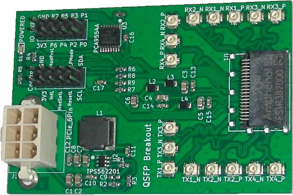
Additional I2C circuitry is due to this being a stepping stone project for an OpenCAPI to dual QSFP design. OpenCAPI has only a single I2C interface.
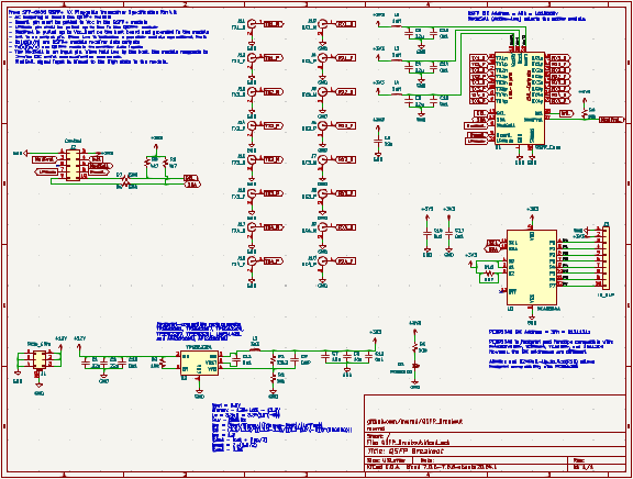
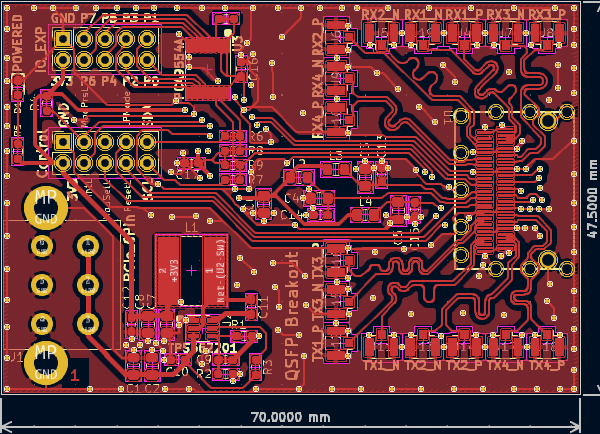
All differential signals are length-matched to within 1mm of a 25mm total length, both inter-pair and intra-pair.
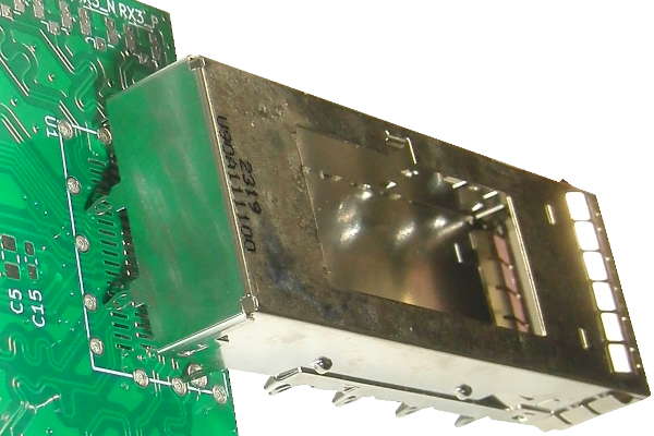
A second revision will be needed as the QSFP Cage Mounting pads are incorrect.
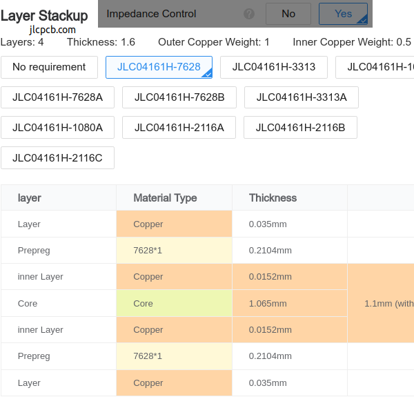
4-Layer PCB stackup taken from JLCPCB.
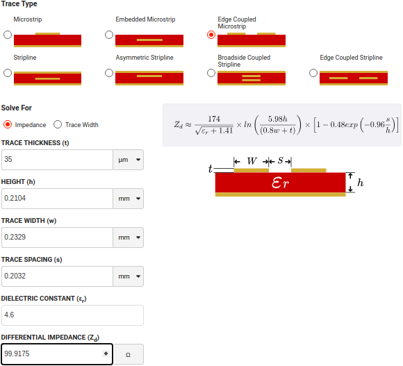
100-ohm Differential Impedance parameters were calculated using the DigiKey Online Calculator.
| Qty | Value | Footprint | References |
|---|---|---|---|
| 8 | 0u1 | Capacitor_SMD:C_0603_1608Metric_Pad1.08x0.95mm_HandSolder | C10, C11, C12, C13, C14, C15, C16, C17 |
| 6 | 22u | Capacitor_SMD:C_0805_2012Metric_Pad1.18x1.45mm_HandSolder | C1, C2, C3, C4, C5, C6 |
| 3 | 10k | Resistor_SMD:R_0603_1608Metric_Pad0.98x0.95mm_HandSolder | R2, R3, R4 |
| 3 | 1uH | Inductor_SMD:L_0805_2012Metric_Pad1.15x1.40mm_HandSolder | L2, L3, L4 |
| 3 | 500 | Resistor_SMD:R_0603_1608Metric_Pad0.98x0.95mm_HandSolder | R5, R6, R7 |
| 2 | 10u | Capacitor_SMD:C_0805_2012Metric_Pad1.18x1.45mm_HandSolder | C7, C8 |
| 2 | 4k7 | Resistor_SMD:R_0603_1608Metric_Pad0.98x0.95mm_HandSolder | R8, R9 |
| 1 | 33k2 | Resistor_SMD:R_0603_1608Metric_Pad0.98x0.95mm_HandSolder | R1 |
| 1 | 3u3 | Inductor_SMD:L_Bourns-SRN8040_8x8.15mm | L1 |
| 1 | Control | Connector_PinSocket_2.54mm:PinSocket_2x05_P2.54mm_Vertical | J2 |
| 1 | DNP | Resistor_SMD:R_0603_1608Metric_Pad0.98x0.95mm_HandSolder | R10 |
| 1 | DNP | Capacitor_SMD:C_0603_1608Metric_Pad1.08x0.95mm_HandSolder | C9 |
| 1 | IO_EXP | Connector_PinSocket_2.54mm:PinSocket_2x05_P2.54mm_Vertical | J3 |
| 1 | PCA9554A | Package_SO:TSSOP-16_4.4x5mm_P0.65mm | U3 |
| 1 | PCIe_6Pin | ATX_Power:ATX_PCIe_6-Pin_Power_Board-Edge | J1 |
| 1 | POWERED | Diode_SMD:D_0603_1608Metric_Pad1.05x0.95mm_HandSolder | D1 |
| 1 | QSFP_Conn | QSFP:QSFP_Conn_w_Cage | U1 |
| 1 | RX1_N | U.FL_w_Label:U.FL_Hirose_w_Label | J19 |
| 1 | RX1_P | U.FL_w_Label:U.FL_Hirose_w_Label | J4 |
| 1 | RX2_N | U.FL_w_Label:U.FL_Hirose_w_Label | J5 |
| 1 | RX2_P | U.FL_w_Label:U.FL_Hirose_w_Label | J6 |
| 1 | RX3_N | U.FL_w_Label:U.FL_Hirose_w_Label | J7 |
| 1 | RX3_P | U.FL_w_Label:U.FL_Hirose_w_Label | J8 |
| 1 | RX4_N | U.FL_w_Label:U.FL_Hirose_w_Label | J9 |
| 1 | RX4_P | U.FL_w_Label:U.FL_Hirose_w_Label | J10 |
| 1 | TPS562201 | Package_TO_SOT_SMD:SOT-23-6 | U2 |
| 1 | TX1_N | U.FL_w_Label:U.FL_Hirose_w_Label | J11 |
| 1 | TX1_P | U.FL_w_Label:U.FL_Hirose_w_Label | J12 |
| 1 | TX2_N | U.FL_w_Label:U.FL_Hirose_w_Label | J13 |
| 1 | TX2_P | U.FL_w_Label:U.FL_Hirose_w_Label | J14 |
| 1 | TX3_N | U.FL_w_Label:U.FL_Hirose_w_Label | J15 |
| 1 | TX3_P | U.FL_w_Label:U.FL_Hirose_w_Label | J16 |
| 1 | TX4_N | U.FL_w_Label:U.FL_Hirose_w_Label | J17 |
| 1 | TX4_P | U.FL_w_Label:U.FL_Hirose_w_Label | J18 |

aerobaticant/Greaseweazle-F7-Plus
My board design for Keir Fraser's Greaseweazle

RubenVoell/iceduino
The basic idea behind this project is to create a simple breakout of an ICE40 FPGA with some LEDs and Buttons to interact with the FPGA and enough resources to run a simple softcore, like a small RISC-V core.

bash227/ECG-Motor-Control-Power-Management-PCB
A multi-function PCB integrating biomedical signal acquisition (ECG), DC motor control, and advanced power management for wearable applications.


Bobrowicz/TPS562201-DC-DC-Converter-Module
2A step down voltage regulator PCB module

cehbz/aqm-fan-controller
KiCad PCB design for a PWM fan controller (ESP32-C3, TPS562201 buck converter)

It measures 70 × 47.5 mm and has 4 copper layers, 1.61 mm thick.
54 parts, built around the TPS562201DDC and PCA9554AD. The full list of its parts is on this page, with links to each part's symbol and footprint where PCBKit's library has them.
From the mwrnd/QSFP_Breakout repository on GitHub, at the commit this page was made from: the board is QSFP_Breakout.kicad_pcb and its schematic QSFP_Breakout.kicad_sch. PCBKit opens the board in the browser, with nothing to install.
Its repository publishes it under the BSD-2-Clause licence: you may reuse it on that licence's terms (keep the author's notice, and for a copyleft licence share your changes alike).