2 layers40 × 34 mm

 mtrudel/rpi-breakout1
A simple Raspberry Pi pHAT to break out common interfaces & GPIO
Rpi breakout is an open-source printed circuit board by mtrudel, from the mtrudel/rpi-breakout repository on GitHub. It is a 2-layer board of 65 × 30 mm with 37 parts on 46 nets, routed with 253 tracks and 0 vias.
Its parts include 22 resistors and 5 connectors. It belongs with the interfaces and adapters boards of this library.
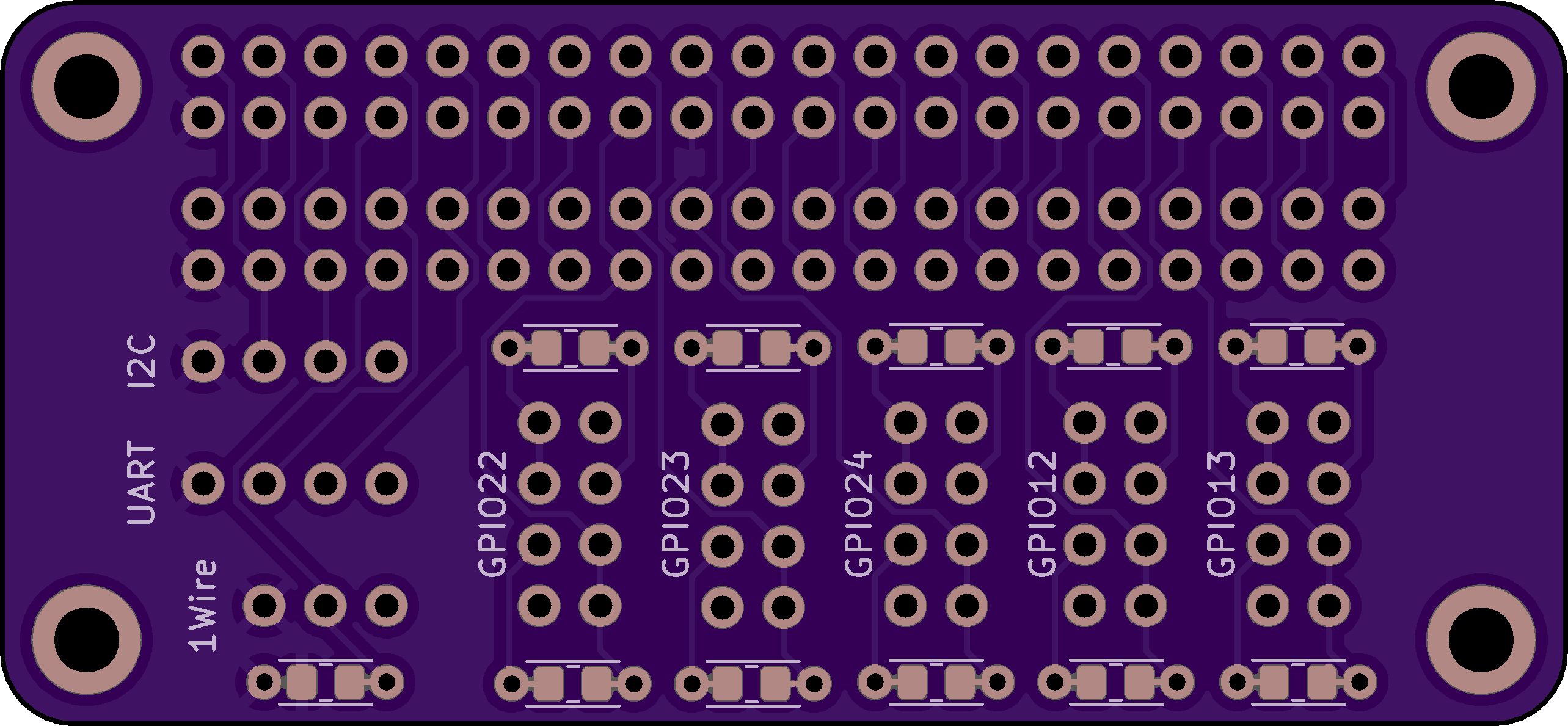
A simple Raspberry Pi pHAT to break out common interfaces & GPIO, with allowances for several common IO setups:
All resistor footprints include allowance for either through-hole or 0805 SMD mounting.
Available at OSH Park.
The board provides the following interfaces:
The 40 pin header is duplicated pin-for-pin; use this for one-off access to pins as needed.
Breaks out the RPi's primary I2C interface (ie: not the EEPROM interface). Pinout is (from left to right looking at the top of the board):
Breaks out the RPi's UART. Pinout is (from left to right looking at the top of the board):
Breaks out the RPi's 1-Wire interface. Pinout is (from left to right looking at the top of the board):
The 1-Wire spec mandates a 4.7k pullup resistor on the data line; this can be done by populating the resistor below the 1-wire header (there is provision to install either a through hole resistor or an 0805 SMD; both connections are wired in parallel)
Five GPIOs are broken out, corresponding to BCM12-BCM13 and BCM22-BCM24. The pinout for each is as follows (looking at the top of the board):
              o||o <-------- <-- Collector current limiting resistor
              |            |
              1  2 <-- 5V  |
              |            |
              3  4 <--------

   ---------> 5  6 <-- GPIO
   |             |
   |  GND --> 7  8 <-- GPIO
   |             |
---------> o||o <-- GPIO current limiting resistorThere are two resistors in each GPIO network. The upper resistor is wired to pin 4 on one end and pins 1&3 on the other. It is intended as a current limiting resistor when a transistor is used to drive a large LED. The lower resistor is wired to pins 5 on one end and 6&8 on the other. It is intended as a current limiting resistor when driving a small LED or a switching transistor directly from the GPIO pin. Both resistor footprints include allowance for either through-hole or 0805 SMD mounting.
Pin 6 is always unpopulated and exposes the GPIO directly. This is useful for probing during development.
This layout looks a bit odd but allows each pin to be conveniently used in a variety of ways. See below for instructions on how to wire up each mode; I promise this will make sense once you use it.
In pictures:
   1  2

   3  4

   5  6

   7  8
   |  |
|__| <-- switchThis comes with the usual caveats about driving LEDs directly off GPIO pins; so long as you're driving small LEDs in a non-continuous manner you should be fine, but caveat emptor etc.
In pictures:
                      1  2

                      3  4

           /|-------- 5  6
 LED ->   | |
           \|-----    7  8

~330Ω resistor -> o||oIn pictures:
  LED resistor   ->    o||o

                       1  2 ---------|\
                                     | | <-- LED
            /|C------  3  4    ------|/
           / |
2N2222 -> |  |B------  5  6
           \ |
            \|E------  7  8

~100Ω resistor -> o||oThis is pretty similar to the previous case of driving a larger LED, but accesses the switching transistor's collector directly. This comes with the usual caveats about transistor / sink sizing etc. It's assumed that you know what you're doing in this scenario.
In pictures:
              Load --> 1  2 <-- 5V if needed

            /|C------  3  4
           / |
2N2222 -> |  |B------  5  6
           \ |
            \|E------  7  8

~100Ω resistor -> o||oMIT
| Qty | Value | Footprint | References |
|---|---|---|---|
| 11 | R | Resistor_THT:R_Axial_DIN0204_L3.6mm_D1.6mm_P5.08mm_Horizontal | R8, R11, R12, R13, R16, R17, R20, R21, R24, R25, R28 |
| 11 | R | Resistor_SMD:R_0805_2012Metric_Pad1.20x1.40mm_HandSolder | R7, R9, R10, R14, R15, R18, R19, R22, R23, R26, R27 |
| 2 | Raspberry_Pi_2_3 | Connector_PinHeader_2.54mm:PinHeader_2x20_P2.54mm_Vertical | J14, J17 |
| 1 | 1Wire | Connector_PinHeader_2.54mm:PinHeader_1x03_P2.54mm_Vertical | J16 |
| 1 | GPIO12 | Connector_PinHeader_2.54mm:PinHeader_2x04_P2.54mm_Vertical | GPIO12 |
| 1 | GPIO13 | Connector_PinHeader_2.54mm:PinHeader_2x04_P2.54mm_Vertical | GPIO13 |
| 1 | GPIO22 | Connector_PinHeader_2.54mm:PinHeader_2x04_P2.54mm_Vertical | GPIO22 |
| 1 | GPIO23 | Connector_PinHeader_2.54mm:PinHeader_2x04_P2.54mm_Vertical | GPIO23 |
| 1 | GPIO24 | Connector_PinHeader_2.54mm:PinHeader_2x04_P2.54mm_Vertical | GPIO24 |
| 1 | I2C | Connector_PinHeader_2.54mm:PinHeader_1x04_P2.54mm_Vertical | J15 |
| 1 | LOGO | Moshozen:Moshozen | G*** |
| 1 | UART | Connector_PinHeader_2.54mm:PinHeader_1x04_P2.54mm_Vertical | J13 |
The 33 most common of 37 parts.

hoglet67/RGBtoHDMI
Bare-metal Raspberry Pi project that provides pixel-perfect sampling of Retro Computer RGB/YUV video and conversion to HDMI

hackclub/OnBoard
💡 Join 1,000 teenagers and make your first PCB with a $100 grant!

FreeYourStream/freedeck-hardware
all the stuff you need to build your own FreeDeck

stuartpittaway/diyBMS
Do it yourself battery management system for Lithium ion battery packs/cells

Pwnsat/FlatSat
Flatsat v1.0 is a hardware based platform for aerospace cybersecurity research


vsfteam/vsf
Versaloon Software Framework -- a tiny preemptive-capable event-driven incremental software framework for embedded systems
It measures 65 × 30 mm and has 2 copper layers, 1.6 mm thick.
37 parts. The full list of its parts is on this page, with links to each part's symbol and footprint where PCBKit's library has them.
From the mtrudel/rpi-breakout repository on GitHub, at the commit this page was made from: the board is rpi-breakout.kicad_pcb and its schematic rpi-breakout.kicad_sch. PCBKit opens the board in the browser, with nothing to install.
Its repository states no licence, so its author keeps all rights: ask mtrudel before reusing the design.