2 layers65 × 56 mm

 MR-DOS/TDR_splitter5
Addon for TDR_avalanche to allow simple TDR cable measurement
TDR splitter is an open-source printed circuit board by MR-DOS, from the MR-DOS/TDR_splitter repository on GitHub, published under the GPL-3.0 licence. It is a 2-layer board of 38.1 × 60.5 mm with 23 parts on 27 nets, routed with 66 tracks and 28 vias.
Its parts include 11 resistors, 7 connectors, 3 capacitors, 1 IC and 1 crystal. It belongs with the radio and wireless and interfaces and adapters boards of this library.
Addon to te TDR_avalanche to allow simple measurement of cable reflections.
This board should be used with the TDR-avalanche to measure cable reflections. The PCB includes trigger generator for the TDR_avalanche, passthrough USB for power supply and resistive splitter to allow connecting a cable and 50 Ohm terminated oscilloscope. The splitter offers 3 ports, 50 Ohm terminated. The signal passes directly over the CABLE port. Insertion loss of the splitter from IN to OUT port is about 20 dB.
Already explained in overview.
The trigger generator can output 2, 4 or 8 kHz square wave. 8 kHz is recommended for the TDR_avalanche.
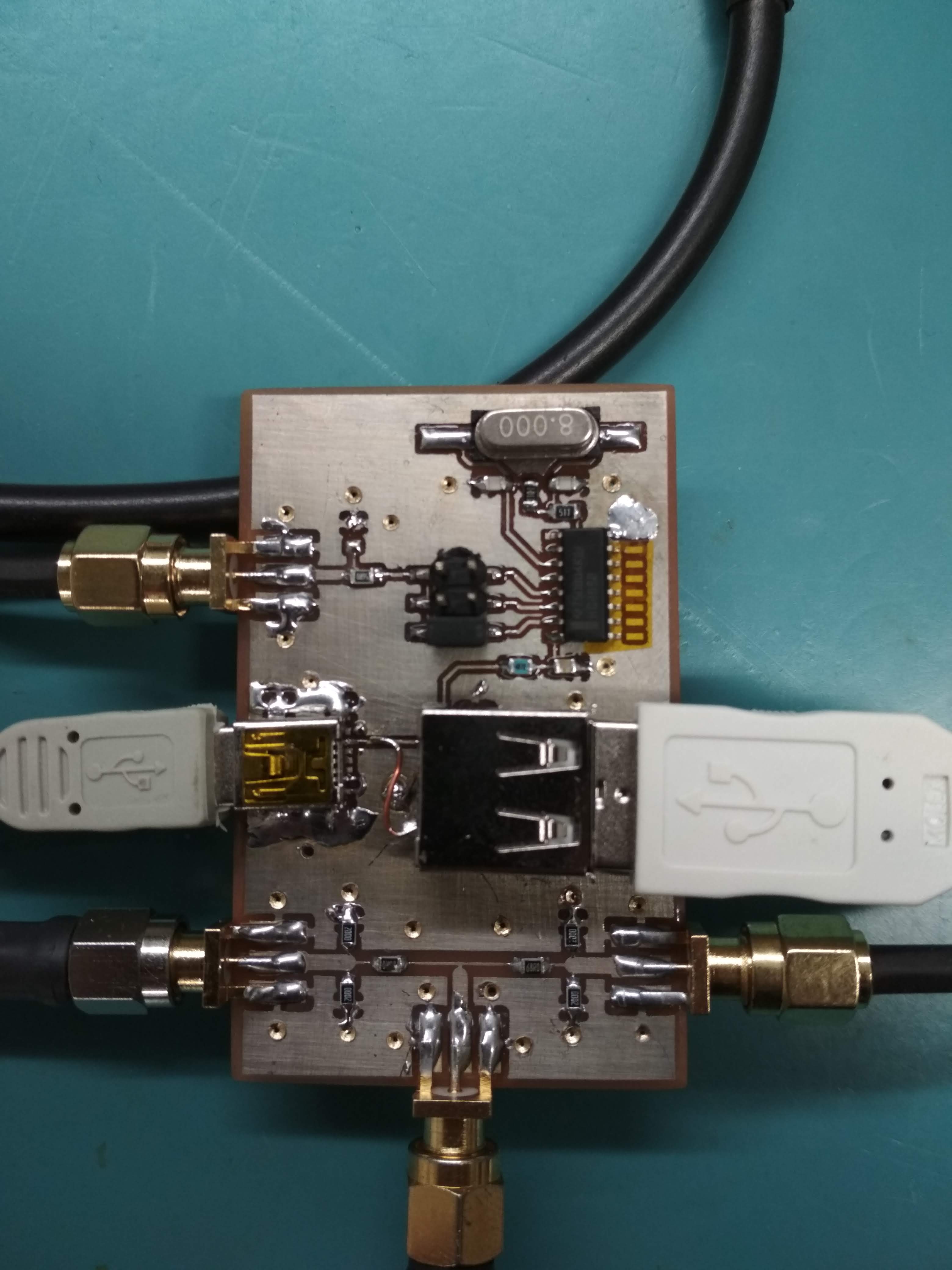
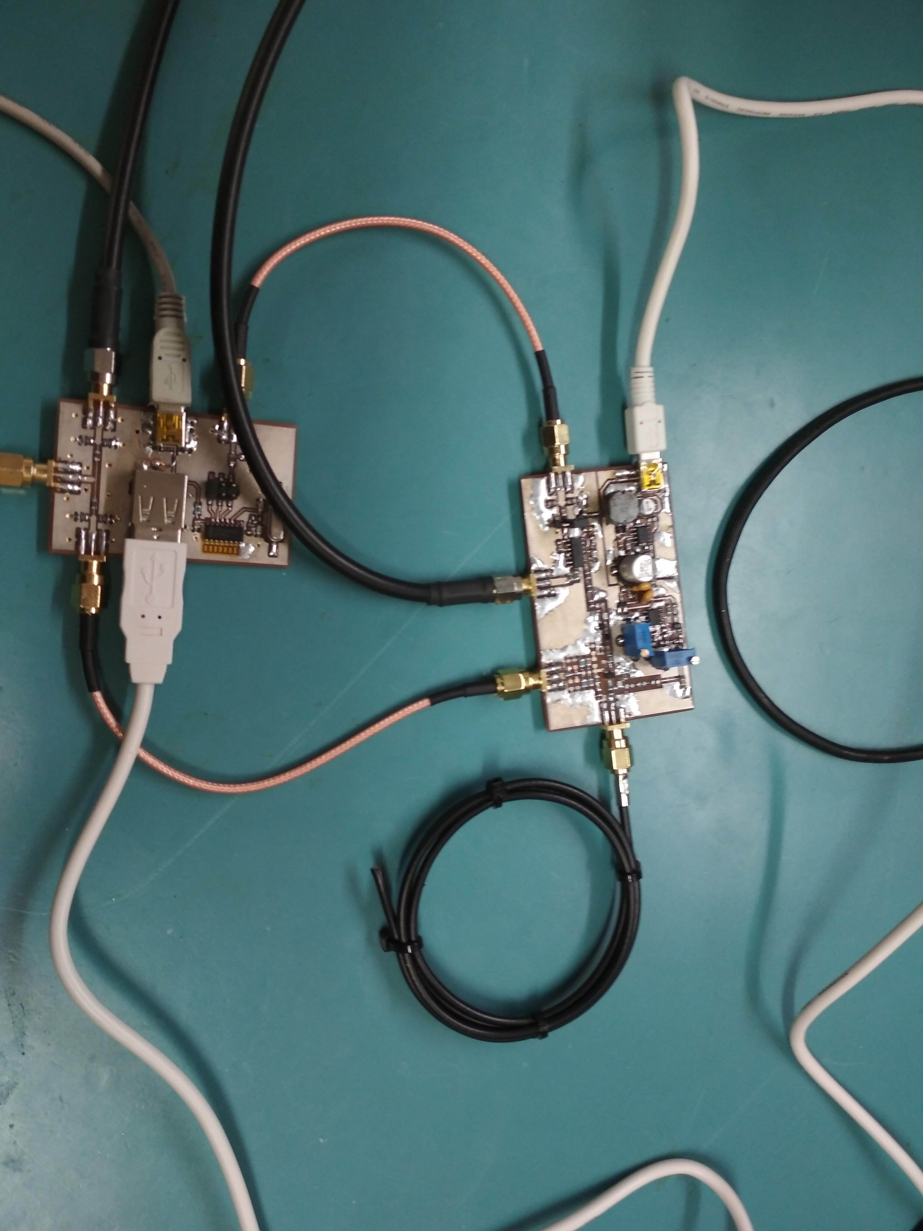
Connect TDR_avalanche to the IN port and TRIG_OUT port. Connect Mini USB B cable as power supply. Connect USB cable to the USB A port and connect the cable to TDR_avalanche. Connect cable under test to CABLE port. Connect 50 Ohm terminated oscilloscope to the OUT port. Connect second oscilloscope input or trigger to SYNC_OUT port of TDR_avalanche. The TDR_avalanche has to be modified to be usable with this board due to the high insertion loss - you have to remove both the attenuators so that in the emitter there are only the 2x 47R resistors and compensation network and there should be 27 Ohm resistor between output and the emitter network so that it is roughly 50 Ohm terminated (in fact, the termination heavily changes during the avalanche pulse, but this does not matter as long as reflections return after the pulse ends).
Connect pulser output to IN port, connect cable under test to the CABLE port. Connect oscilloscope to the OUT port. Separate trigger has to be provided by your pulser board.
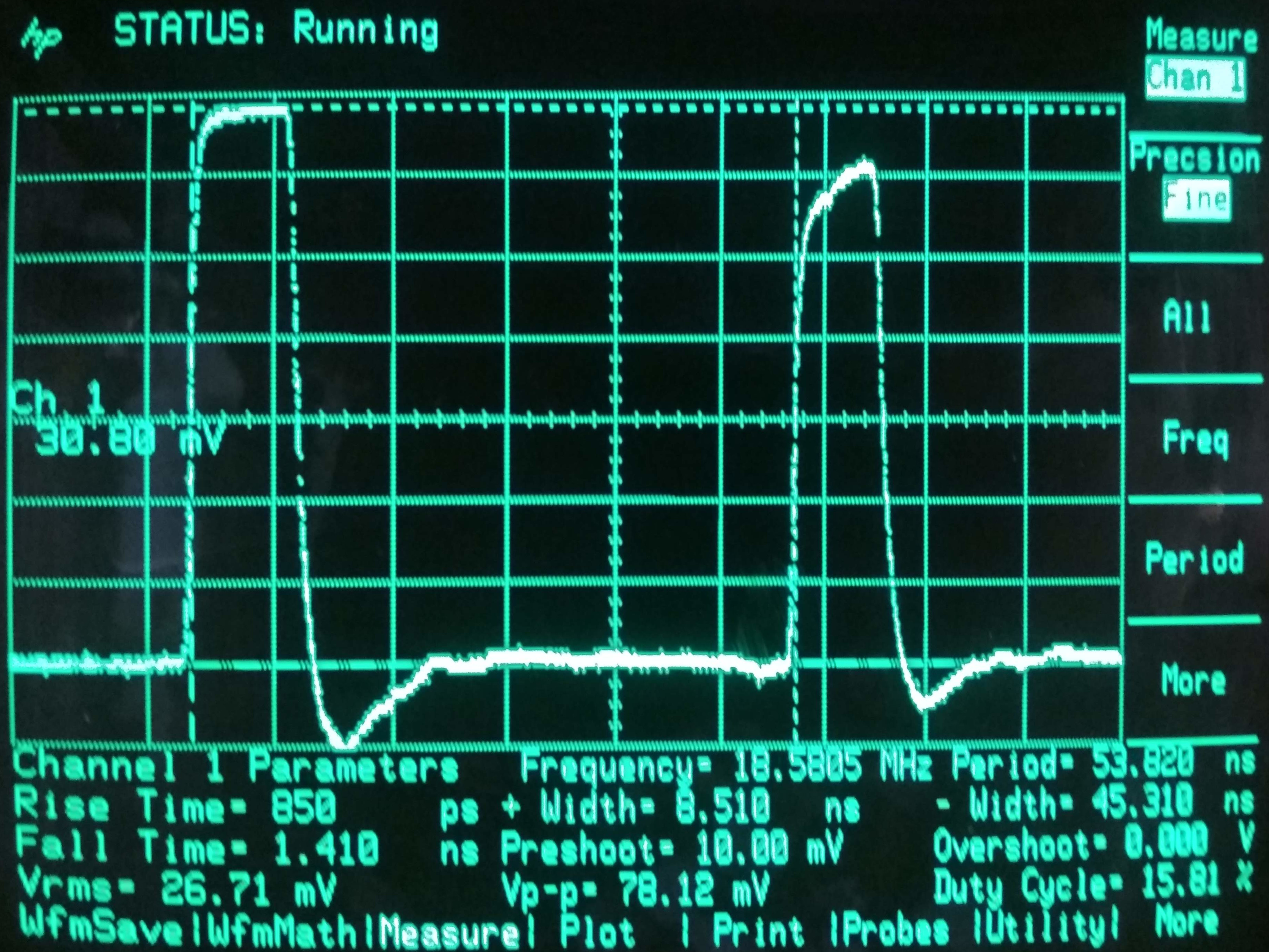
Oscillogram of an unterminated (open) 50 Ohm cable:
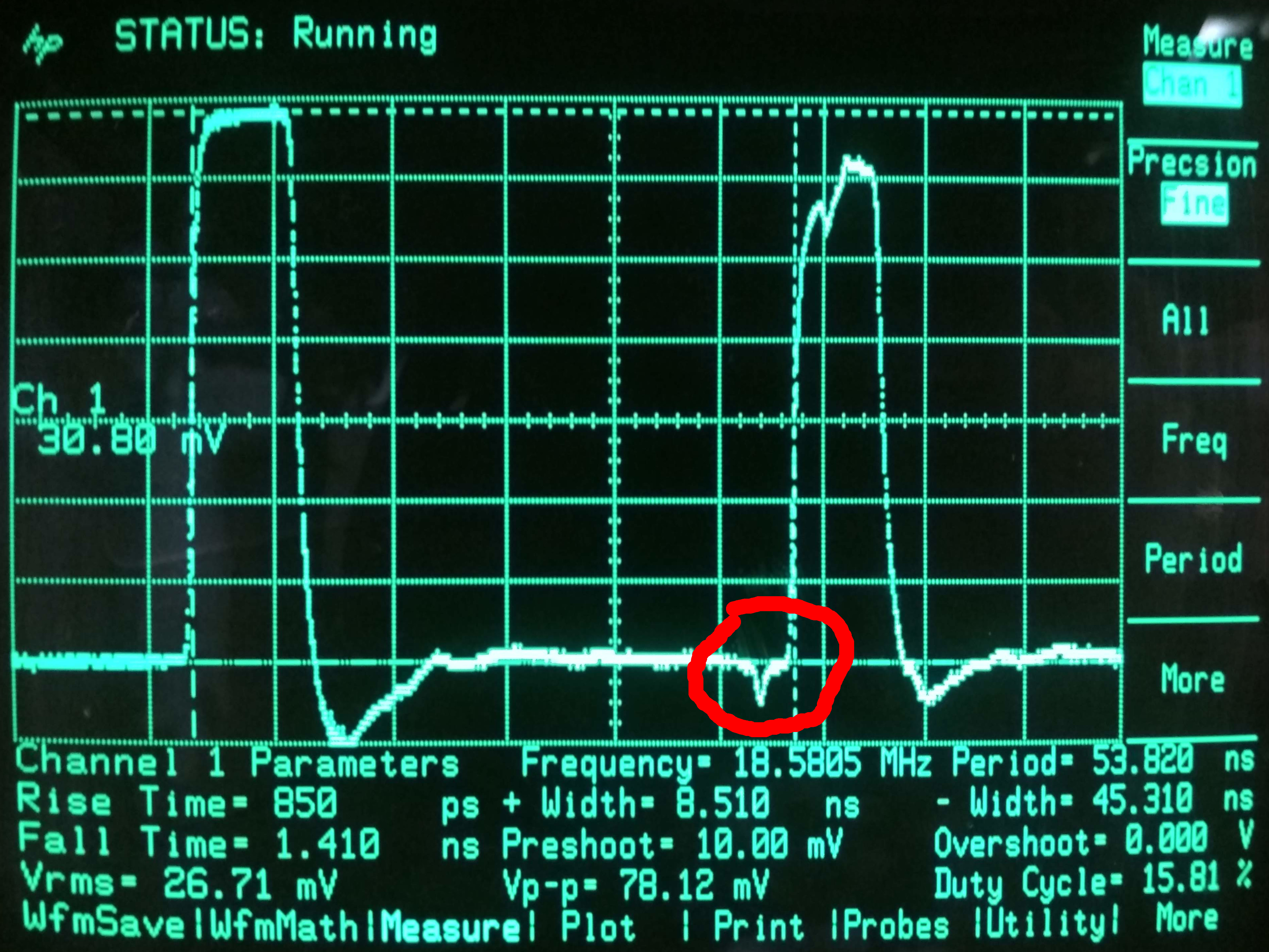
 Oscillogram of an unterminated (open) 50 Ohm cable with defect some 35 cm form the end caused by being heavily pressed using pliers:
 Closeup of the assembled board with all cables connected (please note that the bad IC footprint is already corrected):
 Both the TDR_avalanche and TDR_splitter connected:
Sadly, nothing interesting here. I came up with the splitter in my head at 4AM in bed.
Tweet with photos of the device in use
The PCB uses coplanar waveguide designed for use on standard 1.5 mm FR-4 substrate with 35 um copper (double-sided). It is not very carefully designed and does not give perfect match, but as a prototype, its performance was sufficient. You can modify it for whatever impedance you want, just follow this rule: connect parallel to each of the terminal ports resistor equal to 2x the load impedance, the series resistors should be 4/3x the load impedance and don't forget to update the coplanar waveguide according to the desired impedance.
| Qty | Value | Footprint | References |
|---|---|---|---|
| 4 | 200 | Resistor_SMD:R_0805_2012Metric_Pad1.15x1.40mm_HandSolder | R103, R104, R110, R111 |
| 2 | 22p | Capacitor_SMD:C_0805_2012Metric_Pad1.15x1.40mm_HandSolder | C102, C103 |
| 2 | 68 | Resistor_SMD:R_0805_2012Metric_Pad1.15x1.40mm_HandSolder | R101, R102 |
| 1 | 100n | Capacitor_SMD:C_0805_2012Metric_Pad1.15x1.40mm_HandSolder | C101 |
| 1 | 1M | Resistor_SMD:R_0805_2012Metric_Pad1.15x1.40mm_HandSolder | R108 |
| 1 | 1k | Resistor_SMD:R_0805_2012Metric_Pad1.15x1.40mm_HandSolder | R106 |
| 1 | 4060 | Package_SO:SOIC-16_3.9x9.9mm_P1.27mm | U101 |
| 1 | 4R7 | Resistor_SMD:R_0805_2012Metric_Pad1.15x1.40mm_HandSolder | R105 |
| 1 | 51R | Resistor_SMD:R_0805_2012Metric_Pad1.15x1.40mm_HandSolder | R107 |
| 1 | 8MHz | Crystal:Crystal_SMD_HC49-SD_HandSoldering | Y101 |
| 1 | CABLE | petr_kicad:Molex_SMA_Jack_Edge_Mount_Chinese | J101 |
| 1 | Conn_02x03_Odd_Even | Connector_PinHeader_2.54mm:PinHeader_2x03_P2.54mm_Vertical_SMD | J106 |
| 1 | IN | petr_kicad:Molex_SMA_Jack_Edge_Mount_Chinese | J102 |
| 1 | Not fitted | Resistor_SMD:R_0805_2012Metric_Pad1.15x1.40mm_HandSolder | R109 |
| 1 | OUT | petr_kicad:Molex_SMA_Jack_Edge_Mount_Chinese | J103 |
| 1 | SYNC_GEN | petr_kicad:Molex_SMA_Jack_Edge_Mount_Chinese | J107 |
| 1 | USB_A | Connector_USB:USB_A_CNCTech_1001-011-01101_Horizontal | J105 |
| 1 | USB_B_Mini | Connector_USB:USB_Mini-B_Lumberg_2486_01_Horizontal | J104 |
It measures 38.1 × 60.5 mm and has 2 copper layers, 1.6 mm thick.
23 parts. The full list of its parts is on this page, with links to each part's symbol and footprint where PCBKit's library has them.
From the MR-DOS/TDR_splitter repository on GitHub, at the commit this page was made from: the board is TDR_splitter.kicad_pcb. PCBKit opens the board in the browser, with nothing to install.
Its repository publishes it under the GPL-3.0 licence: you may reuse it on that licence's terms (keep the author's notice, and for a copyleft licence share your changes alike).

google/mozc-devices
Circuit diagrams and firmware source code for Gboard DIY keyboards


Duet3D/Duet-2-Hardware
The KiCAD source for the Duet 3d printer controller see www.duet3d.com