2 layers116.6 × 93.3 mm

 MR-DOS/guitar_down_octave5
A octave-down effect for guitar. All analog, no microcontroller, no DSP.
Guitar down octave is an open-source printed circuit board by MR-DOS, from the MR-DOS/guitar_down_octave repository on GitHub, published under the GPL-3.0 licence. It is a 2-layer board of 147.4 × 63.2 mm with 219 parts on 149 nets, routed with 974 tracks and 70 vias.
It is built around the MC1496D, NE5532 and TL072, with the MC34063AD, MT3608 and NJM4580L among its other parts. Its parts include 93 resistors, 67 capacitors, 20 ICs, 14 diodes and 3 transistors. It belongs with the audio and music boards of this library.


This is an analog guitar effect which works as octave-down effect. Contrary to all available analog octave-down effect (let me know if you find one!), it produces undistorted sinewave (when supplied with pure sinewave on input). There is no PLL, no oscillator
So, you may want to know how it works. A long time ago, I was experimenting with octave-up effects. Recently, I thought that the principle of octave-up effects can be turned inside-out and a bit expanded to make an octave-down effect. The way most octave-up effects work (the good ones, simple ones only rectify the input waveform which is horrible) is as follows:
If this function is inverted, you get:
However, this is not enough to turn sinewave into sinewave of half frequency. You need to remove the absolute value and this is where the analog mojo kicks in. If you want more insight, look in the presentation where simulated waveforms can be found. If you are more curious, look into the schematics or simulation.
To sum it up, the circuit does the following: detect input amplitude and shift the input signal in such a way that the sinewave has its minimum at precisely 0 Vdc, find a square root of the shifted signal and normalize its amplitude so that input and output amplitudes are equal, then invert the signal at points where it gets closest to zero.
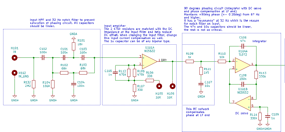
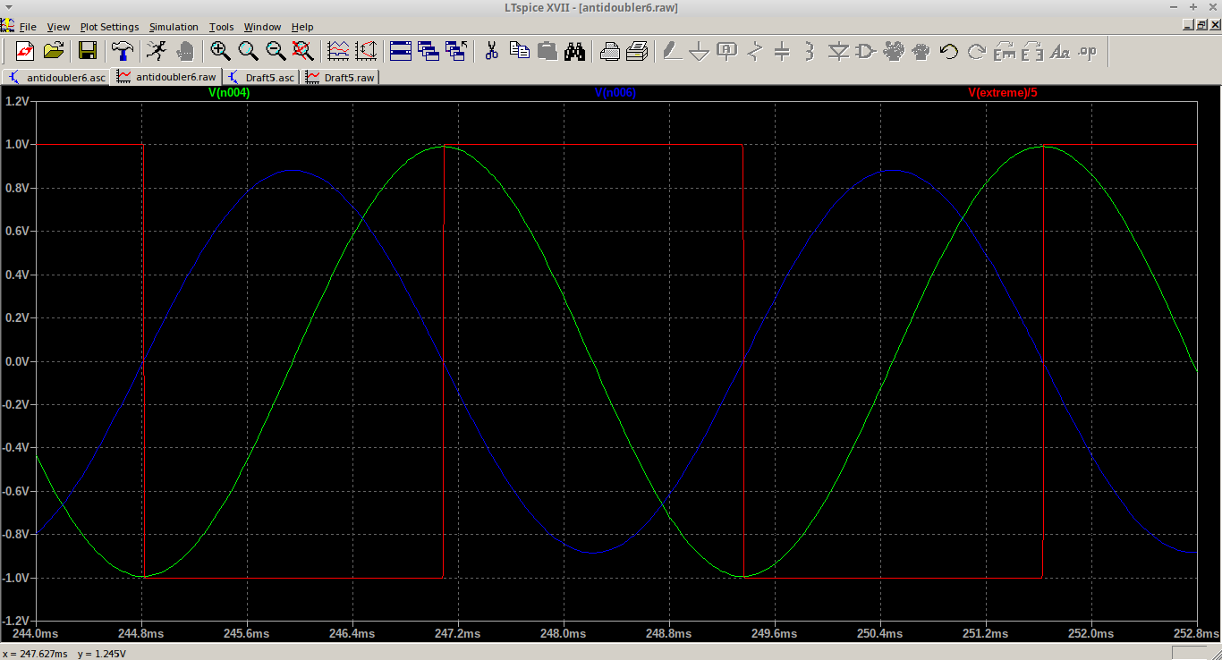
In order to detect extremes, you need to detect zero crossing of a derivation of the input signal. Initially, derivator was used, but it had several issues, most importantly its sensitivity was increasing with frequency whereas I needed quite the opposite, because the circuit needs to be most sensitive in the range of tens of Hz to several hundreds of Hz. The sensitivity also should decrease with rising frequency to make the phasing circuit more immune to harmonics (because signal from guitar is going to be flooded with harmonics). So a double integrator was used - one for the phasing circuit, one as DC servo. However, this circuit has a nasty peak at 32 Hz, so it had to be compensated with a Twin-T notch filter right on the input of the whole effect. It maintains proper 90deg +- 0.25deg phase from about 60 Hz and up. There is an additional RC T-network to accelerate convergence to 90deg at low frequencies, which allows for more gain in the integrator by using shorter time constant. It should work even with harmonic-rich signals, however the harmonics must be in phase (and not antiphase) with the fundamental frequency, otherwise an analysis of what will happen is nontrivial.
Schematics of the input circuit with the notch filter and the phasing circuit:
Green sine is the input waveform, blue is the 90deg shifted sine, red is output of the comparator:
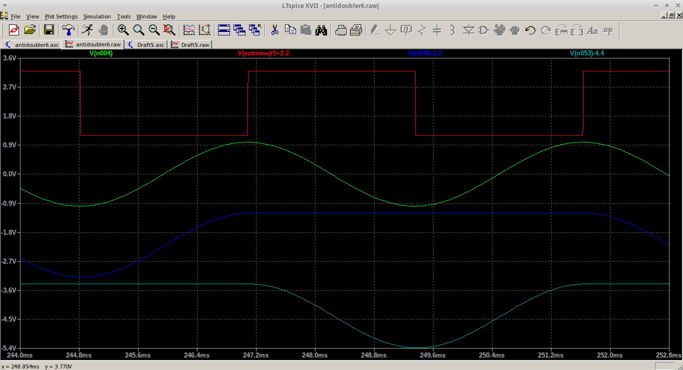
There is a synchronous peak detector which uses 2 track-and-hold amplifiers (historical LF398). One of them tracks the input signal while the second one holds a peak value. Each time the input waveform goes through one of its extremes, their tasks are switched. At the same time, an analog switch selects the one which holds the peak value. This way, you get a fairly precise DC value representing the amplitude which is updated after each cycle of the sinewave. This was needed because regular peak detectors were too slow to react fast enough to dynamics of playing a guitar while being too fast to hold their value during the whole cycle of sinewave, so they would cause a lot of distortion and bad dynamics. This part and the phasing circuit proved to be crucial for proper operation of the whole effect.
Green sine is the input waveform, blue and light blue waveforms are outputs of the track-and-hold amplifiers:
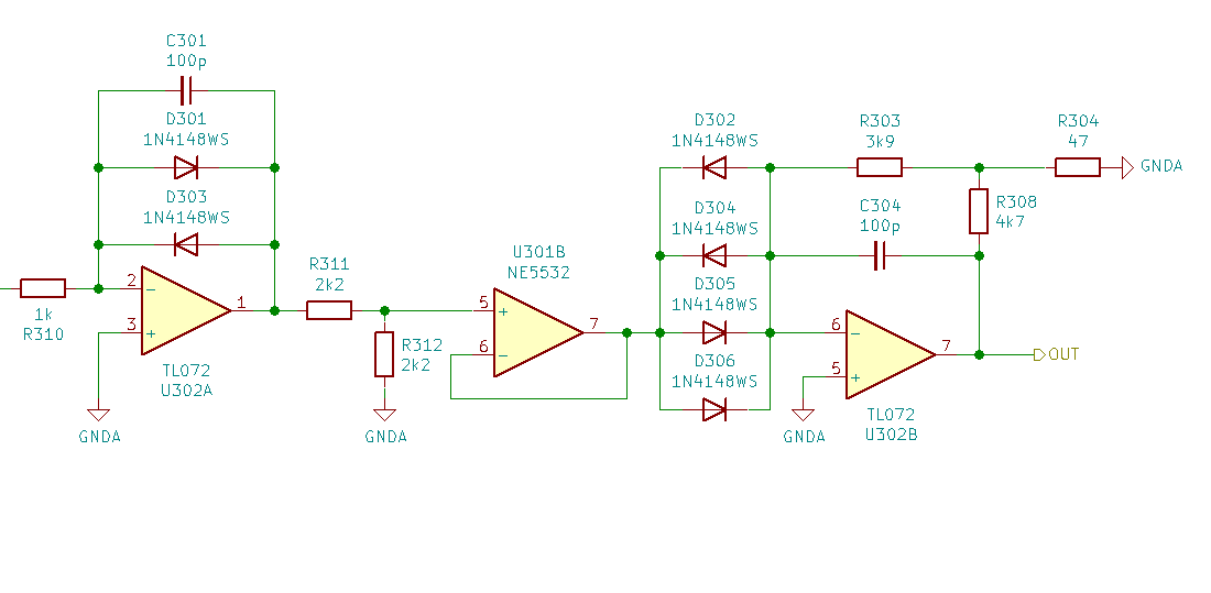
The square root finder is quite simple - it uses opamps and diodes to calculate the logarithm of the DC shifted signal, then divide by two (simple resistor divider) and exponentiate. This computes the square root even with proper sign. The only problem is very low speed of this circuit when crossing zero (which is why it never should cross the zero), because it momentarily goes open-loop and has to cross about 1.3 V rapidly.
Square-root-finder schematics:
Waveforms in the square-root-finder:
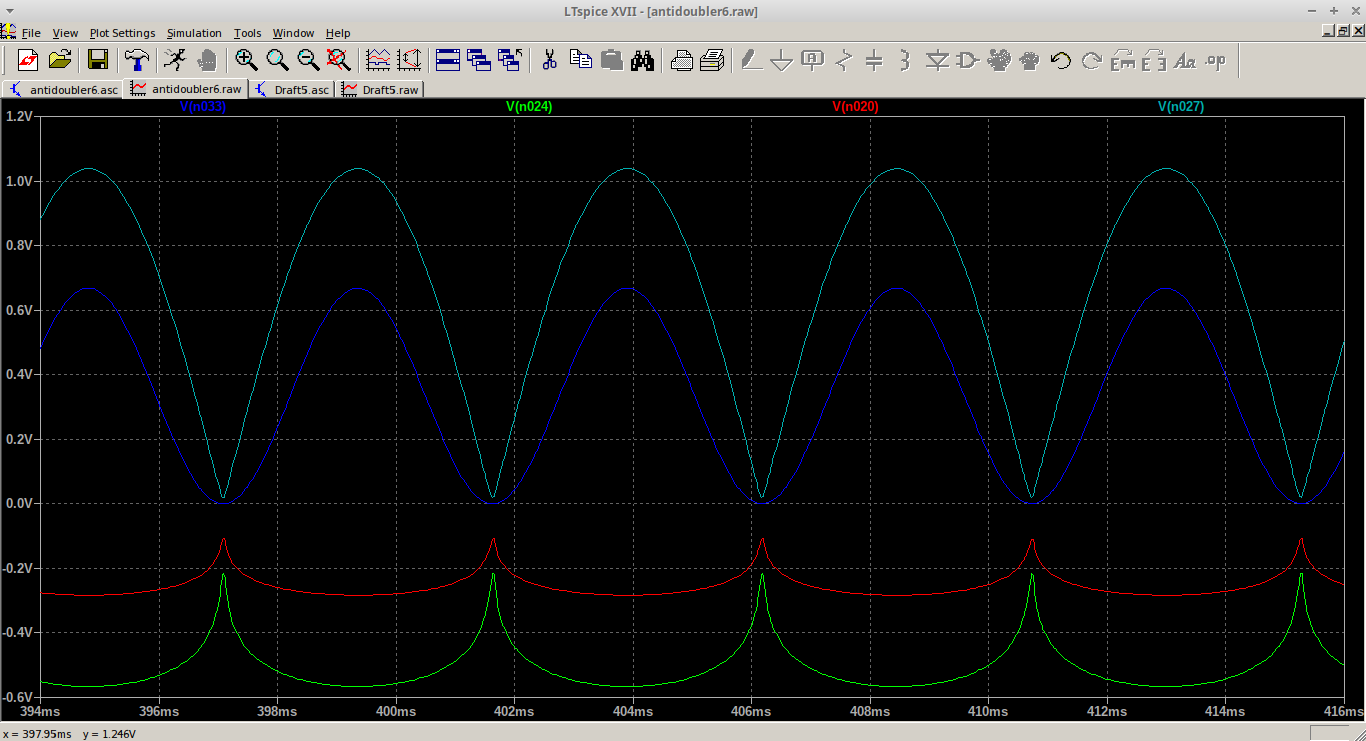
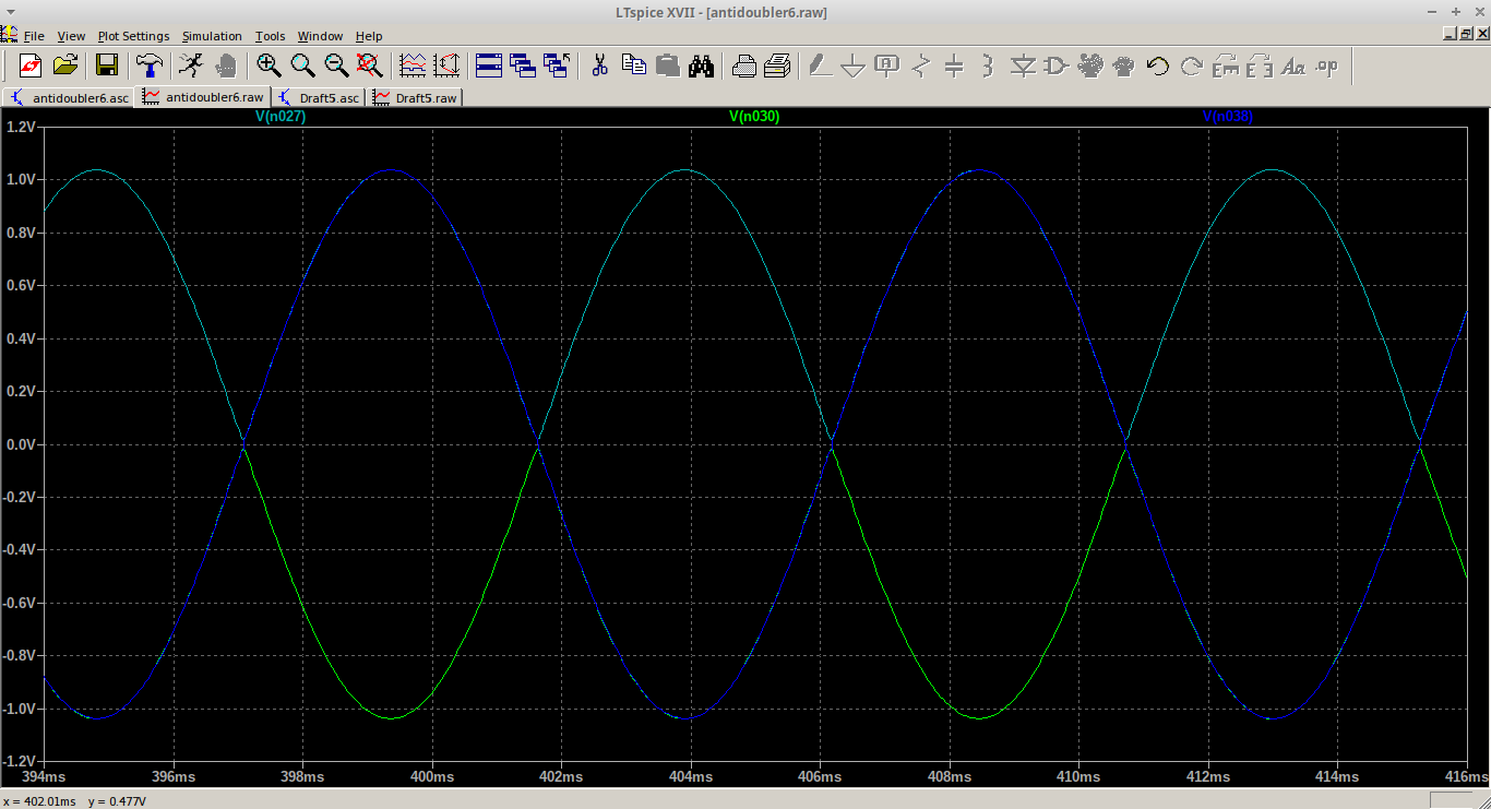
To get rid of the absolute value, there is a synchronous inverter which inverts every second halfperiod of the sinewave. This uses the phasing circuit and 74HC74 to generate half frequency square wave which drives an analog switch which selects either positive or negative halfperiod of the sinewave. There is a simple RC filter to suppress crossover distortion.
Green and light blue line are the noninverted and inverted value, dark blue is the combined waveform:
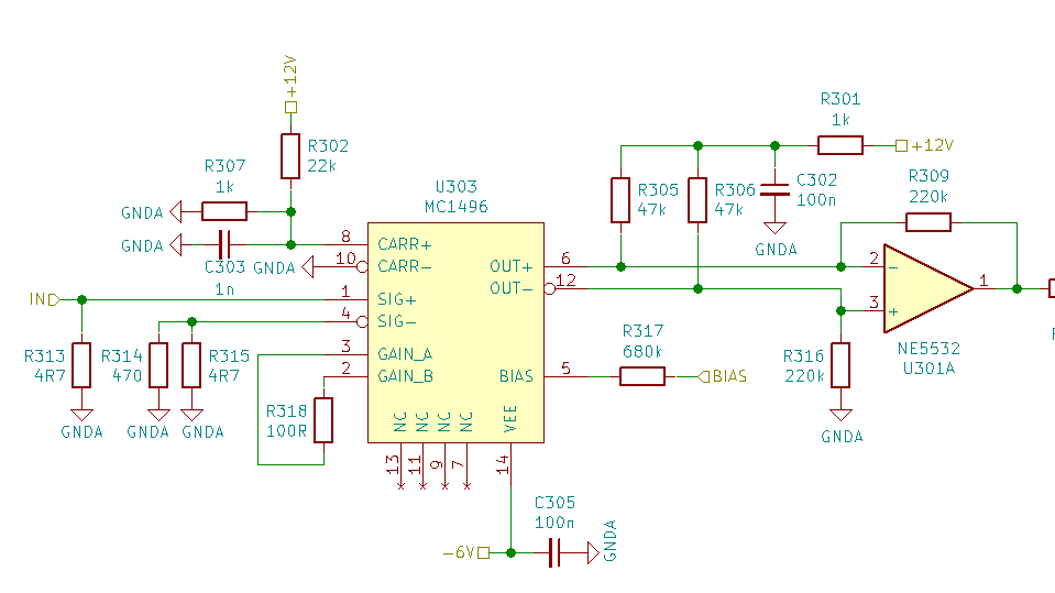
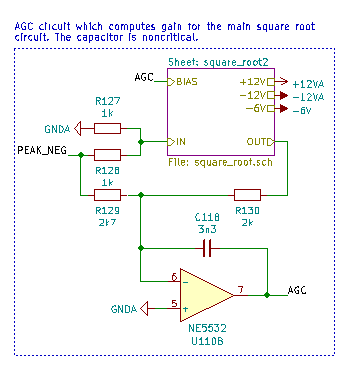
To compensate for amplitude error due to the square-root, there is an AGC which uses Gilbert cells. Each square-root-finder is preceded by the Gilbert cell (there are 2), one has the sine wave as input, the second one gets the DC value of amplitude. The AGC tries to get the input and output amplitude the same.
Gilbert cell used as controlled amplifier:
Feedback used to compute the AGC value:
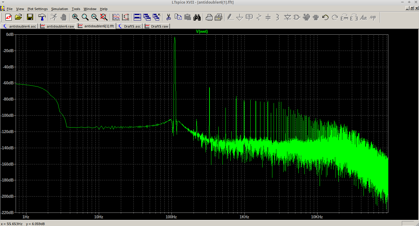
Performance at 110 Hz, 1Vpk-pk: The largest harmonic is the 3rd with -62.3 dBc, the THD is about 0.43% or 2.97% depending on how you define the THD. For a nonlinear guitar effect, it is probably satisfactory.
Image of FFT in simulation:
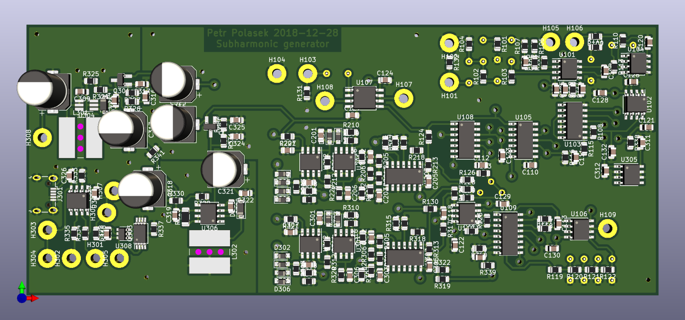
Top view:
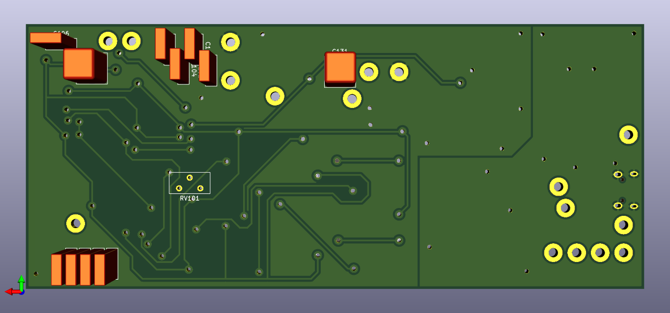
Bottom view:
Top view, drilled and with vias in place:
Bottom view, drilled and with vias in place:
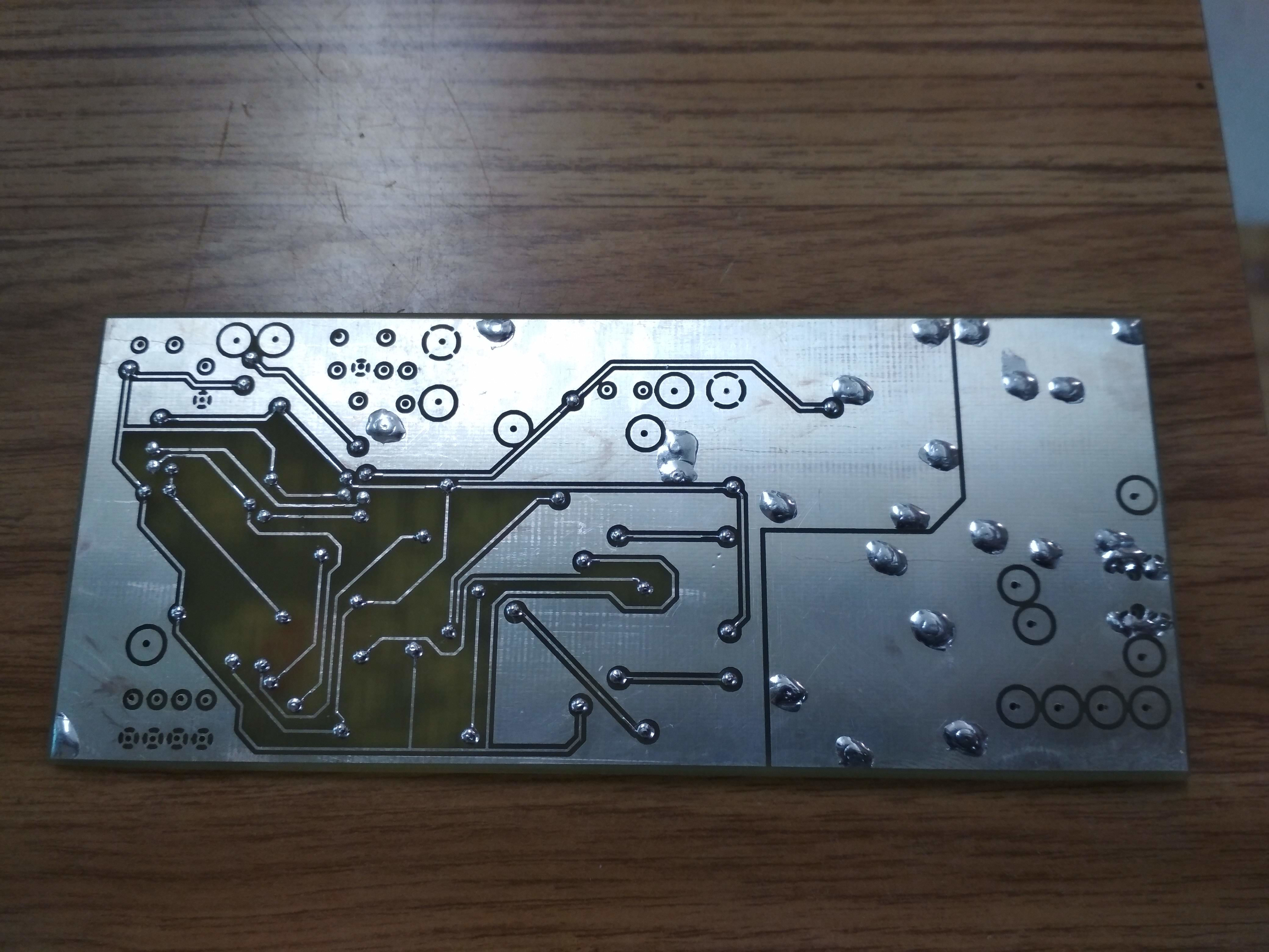
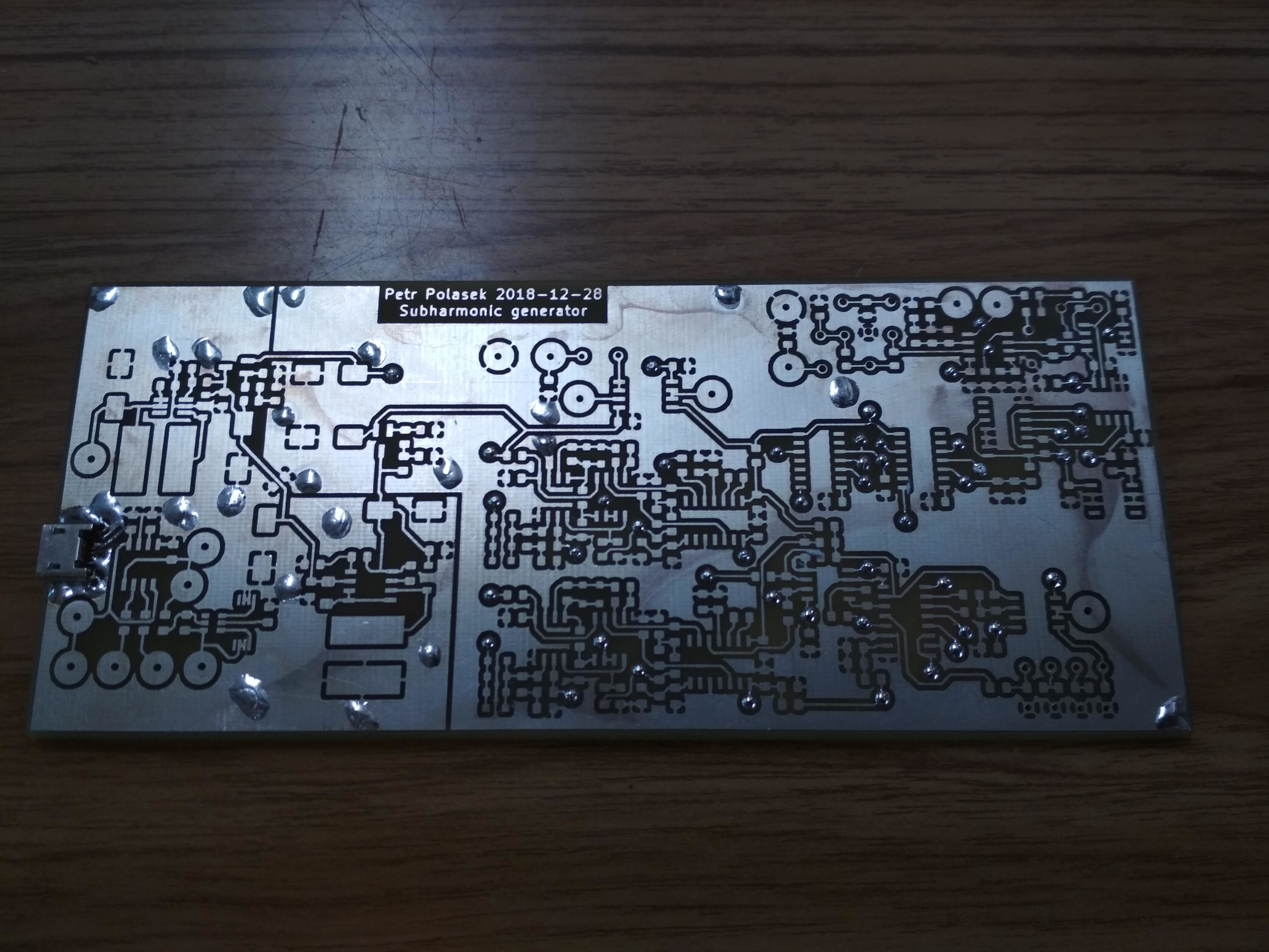
Assembled board:
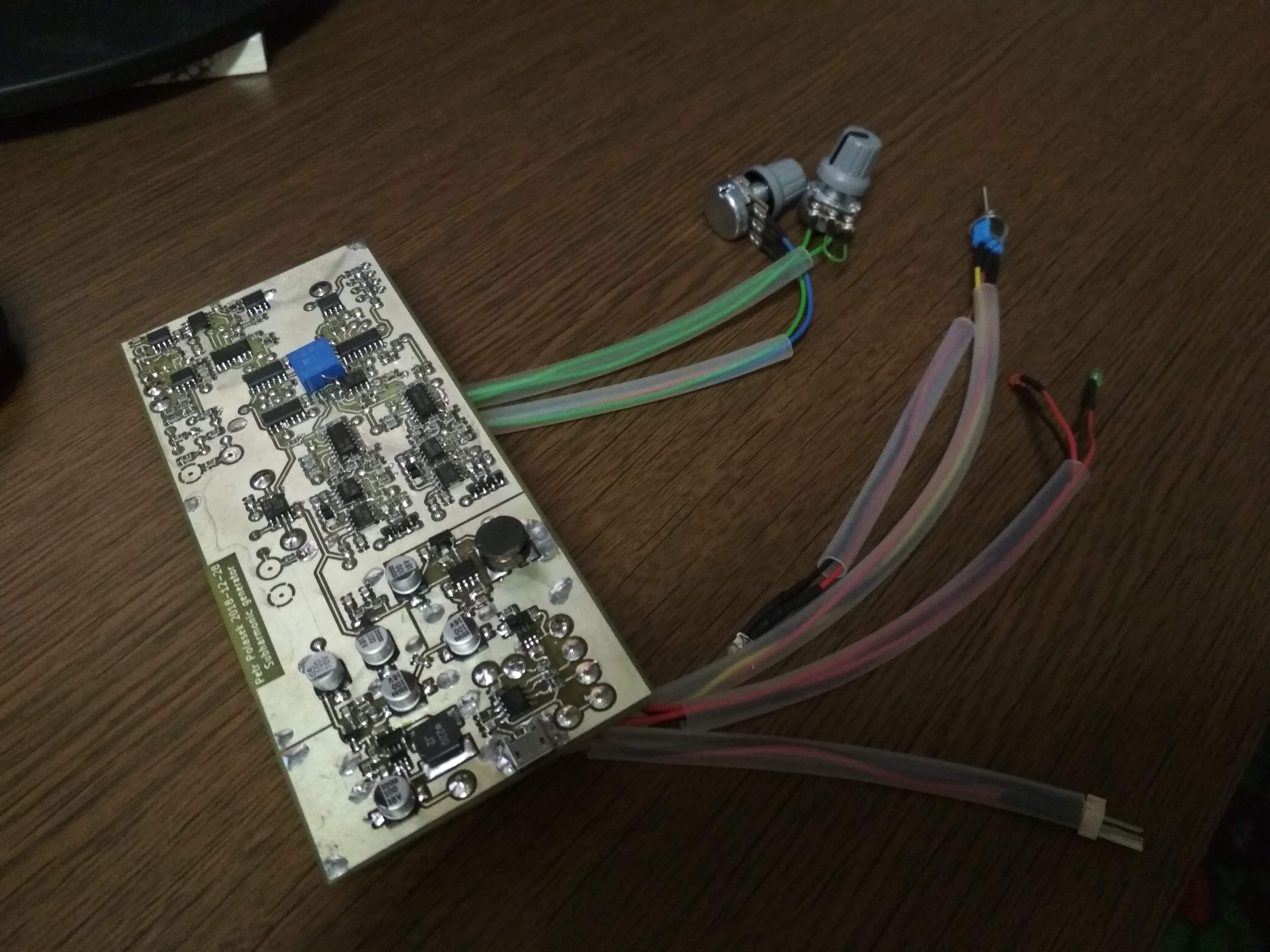
The -15 V switching power supply is a piece of shit. I will never EVER use MC34063, at least for negative power supply. The modern positive switching power supply is OK, it draws only tens of mA. The MC34063 draws one or two orders of magnitude larger current. Maybe it could be replaced by charge pump taken from the positive switching power supply - this means replacing the whole negative power supply by 2 diodes and 1 capacitor.
| Qty | Value | Footprint | References |
|---|---|---|---|
| 18 | 100n | Capacitor_SMD:C_0805_2012Metric_Pad1.15x1.40mm_HandSolder | C110, C111, C112, C202, C205, C206, C207, C302, C305, C306, C307, C309, C311, C312, C314, C319 +2 |
| 16 | 1k | Resistor_SMD:R_0805_2012Metric_Pad1.15x1.40mm_HandSolder | R109, R116, R124, R127, R128, R201, R207, R210, R301, R307, R310, R325, R329, R334, R335, R337 |
| 12 | 10n | Capacitor_SMD:C_0805_2012Metric_Pad1.15x1.40mm_HandSolder | C119, C120, C121, C122, C123, C124, C125, C126, C127, C128, C129, C130 |
| 12 | 1N4148WS | Diode_SMD:D_SOD-323_HandSoldering | D201, D202, D203, D204, D205, D206, D301, D302, D303, D304, D305, D306 |
| 8 | 10k | Resistor_SMD:R_0805_2012Metric_Pad1.15x1.40mm_HandSolder | R110, R117, R118, R326, R327, R331, R332, R339 |
| 7 | 1k5 | Resistor_SMD:R_0805_2012Metric_Pad1.15x1.40mm_HandSolder | R111, R119, R120, R121, R122, R126, R133 |
| 6 | 100u | Capacitor_SMD:CP_Elec_8x10 | C308, C313, C315, C318, C321, C323 |
| 6 | 2k2 | Resistor_SMD:R_0805_2012Metric_Pad1.15x1.40mm_HandSolder | R123, R125, R211, R212, R311, R312 |
| 5 | 100k | Resistor_SMD:R_0805_2012Metric_Pad1.15x1.40mm_HandSolder | R104, R205, R206, R305, R306 |
| 5 | 220k | Resistor_SMD:R_0805_2012Metric_Pad1.15x1.40mm_HandSolder | R131, R209, R216, R309, R316 |
| 5 | 4k7 | Resistor_SMD:R_0805_2012Metric_Pad1.15x1.40mm_HandSolder | R108, R208, R308, R319, R322 |
| 4 | 100R | Resistor_SMD:R_0805_2012Metric_Pad1.15x1.40mm_HandSolder | R218, R318, R336, R338 |
| 4 | 100n | Capacitor_THT:C_Rect_L7.2mm_W2.5mm_P5.00mm_FKS2_FKP2_MKS2_MKP2 | C101, C102, C103, C104 |
| 4 | 100p | Capacitor_SMD:C_0805_2012Metric_Pad1.15x1.40mm_HandSolder | C201, C204, C301, C304 |
| 4 | 220 | Resistor_SMD:R_0805_2012Metric_Pad1.15x1.40mm_HandSolder | R220, R221, R320, R321 |
| 4 | 4R7 | Resistor_SMD:R_0805_2012Metric_Pad1.15x1.40mm_HandSolder | R213, R215, R313, R315 |
| 4 | 680n | Capacitor_SMD:C_0805_2012Metric_Pad1.15x1.40mm_HandSolder | C316, C317, C324, C325 |
| 4 | NE5532 | Package_SO:SOIC-8_3.9x4.9mm_P1.27mm | U101, U110, U201, U301 |
| 4 | TL072 | Package_SO:SOIC-8_3.9x4.9mm_P1.27mm | U104, U106, U202, U302 |
| 3 | 1n | Capacitor_SMD:C_0805_2012Metric_Pad1.15x1.40mm_HandSolder | C113, C203, C303 |
| 3 | 1u | Capacitor_SMD:C_0805_2012Metric_Pad1.15x1.40mm_HandSolder | C105, C109, C329 |
| 3 | 22n | Capacitor_THT:C_Rect_L7.2mm_W2.5mm_P5.00mm_FKS2_FKP2_MKS2_MKP2 | C114, C115, C116 |
| 3 | 3k9 | Resistor_SMD:R_0805_2012Metric_Pad1.15x1.40mm_HandSolder | R115, R203, R303 |
| 2 | 10K | MountingHole:MountingHole_2.2mm_M2_Pad | H105, H106 |
| 2 | 10u | Capacitor_SMD:C_0805_2012Metric_Pad1.15x1.40mm_HandSolder | C326, C327 |
| 2 | 1N5819 | Diode_SMD:D_SOD-123 | D307, D308 |
| 2 | 220u | Inductor_SMD:L_Wuerth_WE-PD2-Typ-XL | L301, L302 |
| 2 | 22k | Resistor_SMD:R_0805_2012Metric_Pad1.15x1.40mm_HandSolder | R202, R302 |
| 2 | 330 | Resistor_SMD:R_0805_2012Metric_Pad1.15x1.40mm_HandSolder | R106, R107 |
| 2 | 330k | Resistor_SMD:R_0805_2012Metric_Pad1.15x1.40mm_HandSolder | R113, R114 |
| 2 | 47 | Resistor_SMD:R_0805_2012Metric_Pad1.15x1.40mm_HandSolder | R204, R304 |
| 2 | 470 | Resistor_SMD:R_0805_2012Metric_Pad1.15x1.40mm_HandSolder | R214, R314 |
| 2 | 470k | Resistor_SMD:R_0805_2012Metric_Pad1.15x1.40mm_HandSolder | R105, R112 |
| 2 | 680k | Resistor_SMD:R_0805_2012Metric_Pad1.15x1.40mm_HandSolder | R217, R317 |
| 2 | 68k | Resistor_SMD:R_0805_2012Metric_Pad1.15x1.40mm_HandSolder | R102, R103 |
| 2 | LF398_SOIC8 | Package_SO:SOIC-14_3.9x8.7mm_P1.27mm | U105, U108 |
| 2 | MC1496 | Package_SO:SOIC-14_3.9x8.7mm_P1.27mm | U203, U303 |
| 1 | 0R33 | Resistor_SMD:R_1206_3216Metric_Pad1.42x1.75mm_HandSolder | R328 |
| 1 | 10n | Capacitor_THT:C_Rect_L7.2mm_W2.5mm_P5.00mm_FKS2_FKP2_MKS2_MKP2 | C117 |
| 1 | 10u | Capacitor_THT:C_Rect_L7.2mm_W7.2mm_P5.00mm_FKS2_FKP2_MKS2_MKP2 | C107 |
| 1 | 11k | Resistor_SMD:R_0805_2012Metric_Pad1.15x1.40mm_HandSolder | R330 |
| 1 | 150n | Capacitor_SMD:C_0805_2012Metric_Pad1.15x1.40mm_HandSolder | C108 |
| 1 | 18k | Resistor_SMD:R_0805_2012Metric_Pad1.15x1.40mm_HandSolder | R101 |
| 1 | 1K_H | MountingHole:MountingHole_2.2mm_M2_Pad | H109 |
| 1 | 1K_L | MountingHole:MountingHole_2.2mm_M2_Pad | H107 |
| 1 | 1K_W | MountingHole:MountingHole_2.2mm_M2_Pad | H108 |
| 1 | 1k2 | Resistor_SMD:R_0805_2012Metric_Pad1.15x1.40mm_HandSolder | R333 |
| 1 | 1u | Capacitor_THT:C_Rect_L7.2mm_W7.2mm_P5.00mm_FKS2_FKP2_MKS2_MKP2 | C131 |
| 1 | 220p | Capacitor_SMD:C_0805_2012Metric_Pad1.15x1.40mm_HandSolder | C132 |
| 1 | 22R | Resistor_SMD:R_0805_2012Metric_Pad1.15x1.40mm_HandSolder | R341 |
| 1 | 24k | Resistor_SMD:R_0805_2012Metric_Pad1.15x1.40mm_HandSolder | R324 |
| 1 | 2M2 | Resistor_SMD:R_0805_2012Metric_Pad1.15x1.40mm_HandSolder | R132 |
| 1 | 2N7002 | Package_TO_SOT_SMD:SOT-23_Handsoldering | Q301 |
| 1 | 2k | Resistor_SMD:R_0805_2012Metric_Pad1.15x1.40mm_HandSolder | R130 |
| 1 | 2k7 | Resistor_SMD:R_0805_2012Metric_Pad1.15x1.40mm_HandSolder | R129 |
| 1 | 330p | Capacitor_SMD:C_0805_2012Metric_Pad1.15x1.40mm_HandSolder | C320 |
| 1 | 3n3 | Capacitor_SMD:C_0805_2012Metric_Pad1.15x1.40mm_HandSolder | C118 |
| 1 | 47n | Capacitor_THT:C_Rect_L7.2mm_W2.5mm_P5.00mm_FKS2_FKP2_MKS2_MKP2 | C106 |
| 1 | 6k8 | Resistor_SMD:R_0805_2012Metric_Pad1.15x1.40mm_HandSolder | R340 |
| 1 | 74HC74 | Package_SO:SOIC-14_3.9x8.7mm_P1.27mm | U103 |
| 1 | BATT+ | MountingHole:MountingHole_2.2mm_M2_Pad | H306 |
| 1 | BATT- | MountingHole:MountingHole_2.2mm_M2_Pad | H305 |
| 1 | BSS84 | Package_TO_SOT_SMD:SOT-23_Handsoldering | Q302 |
| 1 | CD4053B | Package_SO:SOIC-16_3.9x9.9mm_P1.27mm | U109 |
| 1 | DW01 | Package_TO_SOT_SMD:SOT-23-6 | U308 |
| 1 | FS8205 | Package_SO:TSSOP-8_4.4x3mm_P0.65mm | Q303 |
| 1 | IN | MountingHole:MountingHole_2.2mm_M2_Pad | H101 |
| 1 | IN_GND | MountingHole:MountingHole_2.2mm_M2_Pad | H102 |
| 1 | L78L05_SO8 | Package_SO:SOIC-8_3.9x4.9mm_P1.27mm | U305 |
| 1 | LED_CHG+ | MountingHole:MountingHole_2.2mm_M2_Pad | H303 |
| 1 | LED_CHG- | MountingHole:MountingHole_2.2mm_M2_Pad | H301 |
| 1 | LED_STDBY+ | MountingHole:MountingHole_2.2mm_M2_Pad | H304 |
| 1 | LED_STDBY- | MountingHole:MountingHole_2.2mm_M2_Pad | H302 |
| 1 | LM311 | Package_SO:SOIC-8_3.9x4.9mm_P1.27mm | U102 |
| 1 | MC34063AD | Package_SO:SOIC-8_3.9x4.9mm_P1.27mm | U306 |
| 1 | MT3608 | Package_TO_SOT_SMD:TSOT-23-6_HandSoldering | U304 |
| 1 | NJM4580 | Package_SO:SOIJ-8_5.3x5.3mm_P1.27mm | U107 |
| 1 | OUT | MountingHole:MountingHole_2.2mm_M2_Pad | H103 |
| 1 | OUT_GND | MountingHole:MountingHole_2.2mm_M2_Pad | H104 |
| 1 | R_POT | Potentiometer_THT:Potentiometer_Bourns_3296Y_Vertical | RV101 |
The 215 most common of 219 parts.

charbel-j-estephan/Fm_Stereo_Encoder_Decoder
FM stereo encoder and decoder with 19 kHz pilot, designed in LTspice and KiCad.

46nori/FMSynthEnsemble
USB MIDI FM synthesizer that supports voice synthesis using CSM (Composite Sinusoidal Model

KushlaVR/models-heart
Можливості: Керування через WIFI з телефона або ПК 5 незалежних каналів (світлодіоди/сервомотори) 1 Н-міст для підключення мотора (піковий струм до 3А) Вмонтована BMS 1S та контроллер заряду Li-Ion акумулятора з…

brev-dev/another_esp8266_sensor_board
PCB layout and instructions for a multi-purpose esp8266 sensor device, with optional LORA connectivity.


EmaNeg/Power_Management_Unit_Tesi
PMU (Power Management Unit) compatta per sistemi embedded. Integra Power Path automatico, ricarica Li-Po 1S, conversione DC-DC Buck-Boost a 5V e monitoraggio I2C tramite MAX17048.
It measures 147.4 × 63.2 mm and has 2 copper layers, 1.6 mm thick.
219 parts, built around the MC1496D, NE5532, TL072 and MC34063AD. The full list of its parts is on this page, with links to each part's symbol and footprint where PCBKit's library has them.
From the MR-DOS/guitar_down_octave repository on GitHub, at the commit this page was made from: the board is kicad/guitar_down_octave.kicad_pcb. PCBKit opens the board in the browser, with nothing to install.
Its repository publishes it under the GPL-3.0 licence: you may reuse it on that licence's terms (keep the author's notice, and for a copyleft licence share your changes alike).