2 layers64.5 × 120.5 mm
X de link
Monacrylic/Pinscope-benchmark-circuits
This repository contains a suite of sample KiCad circuits used as benchmarks for Pinscope.
122 parts2

 Monacrylic/Pinscope-benchmark-circuits2
This repository contains a suite of sample KiCad circuits used as benchmarks for Pinscope.
DroneController is an open-source printed circuit board by Monacrylic, from the Monacrylic/Pinscope-benchmark-circuits repository on GitHub. It is a 4-layer board of 55 × 55 mm with 74 parts on 75 nets, routed with 450 tracks and 126 vias.
It is built around the L86-M33, BMP280 and W25Q16JVSSIQ, with the AP7361C-33E, ICM-42605 and AO3400A among its other parts. Its parts include 22 capacitors, 14 resistors, 7 ICs, 4 diodes and 2 transistors. It belongs with the STM32 boards of this library.


This repository contains a suite of sample KiCad circuits used as benchmarks for Pinscope.
The suite is designed to test, validate, and evaluate Pinscope's capabilities in circuit analysis, fault coverage, and netlist validation.
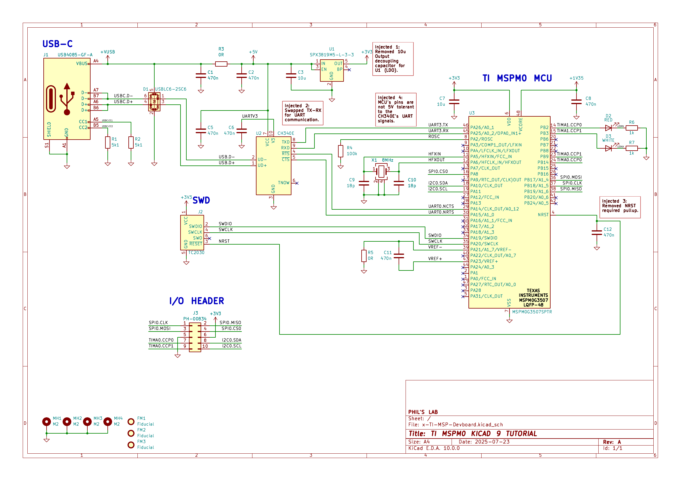 Example benchmark circuit: the fault-injected TI MSP Devboard (
x-TI-MSP-Devboard). The red text boxes mark the injected faults.
The repository represents four distinct projects. For each project, there are two versions:
Original-schematics/.x-.| Project Name | Original Folder | Fault-Injected Folder (x-) | Description |
|---|---|---|---|
| TI MSP Devboard | Original-schematics/TI-MSP-Devboard | x-TI-MSP-Devboard | TI MSPM0G3507 microcontroller development board. |
| Open-Smartwatch Light | Original-schematics/osw-light | x-osw-light | Light edition of the Open-Smartwatch KiCad project. |
| STM32 FPV Drone Controller | Original-schematics/DroneController-main | x-drone-controller | STM32F411-based FPV drone flight controller. |
| de-link-pcb | Original-schematics/de-link-pcb-master | x-de-link | de-link-pcb open-hardware board. |
Each fault-injected (x-) folder documents its specific faults in an injected-errors.md file (columns: S.No, Designator, Error Description), generated by reading the text_box annotations in that project's .kicad_sch.
The taxonomy below is the union of fault types across all injected projects. It is regenerated whenever the per-project injected-errors.md files are (re)populated.
| # | Error Class | Description | Seen in |
|---|---|---|---|
| 1 | Missing component | A required part (decoupling capacitor, pull-up/pull-down, current-set, gate, or protection component) omitted from the netlist. | x-TI-MSP-Devboard, x-de-link, x-drone-controller |
| 2 | Missing connection | A net or label absent, leaving a pin, supply, or ground floating. | x-osw-light, x-drone-controller |
| 3 | Swapped connection | Two nets interchanged (e.g., UART TX↔RX). | x-TI-MSP-Devboard, x-osw-light, x-drone-controller |
| 4 | Incorrect component value | Correct part type but wrong value (e.g., 100k where 10k is specified). | x-osw-light |
| 5 | Reversed polarity | A polarized part (diode/LED) or transistor placed with reversed/flipped terminals. | x-osw-light, x-de-link, x-drone-controller |
| 6 | Stuck / mis-tied control pin | A control/strap pin tied to the wrong fixed rail (e.g., enable to GND, boot pin pulled high instead of low). | x-osw-light, x-de-link, x-drone-controller |
| 7 | Electrical incompatibility | An interconnect that violates device limits (e.g., non-5V-tolerant pins driven by 5V signals). | x-TI-MSP-Devboard, x-drone-controller |
| 8 | Shorted component/net | A component or net bridged/shorted out (e.g., a feedback-divider resistor shorted to 0 Ω). | x-de-link, x-drone-controller |
| 9 | Pin resource conflict | A pin reserved for one function reused for another (e.g., IO35 reserved by PSRAM reassigned to I/O). | x-de-link |
You can also inspect the .csv or .asc netlist changes in the corresponding x- folders (e.g., x-TI-MSP-Devboard/x-TI-MSP-Devboard.csv) for specific injection details.
Each fault-injected project was analyzed with Pinscope; the per-project findings are recorded in the *-findings.xlsx file inside each x- folder. The tables below cross-reference every injected fault (numbered as in that project's injected-errors.md) against the Pinscope finding that identifies it.
Legend: ✅ Detected — a finding directly identifies the injected fault. 🟡 Detected (partial/assumed) — a finding flags the affected component/net in a way consistent with the injected fault, or the fault sits on a part whose datasheet was not accessible to Pinscope in this run (the check could not have fired for lack of reference data, not for lack of checking); counted as detected. ❌ Not detected in this run. Injected entries that produce no electrical change (annotation-only duplicates or connectivity-neutral edits) are excluded from the coverage denominator.
| Project | Evaluable injected faults | Detected | Coverage |
|---|---|---|---|
| TI MSP Devboard | 4 | 3 | 75% |
| Open-Smartwatch Light | 5 | 3 | 60% |
| STM32 FPV Drone Controller | 9 | 5 | 56% |
| de-link-pcb | 8 | 6 | 75% |
| Total | 26 | 17 | 65.4% |
Pinscope caught roughly two out of every three injected faults. Detection is strongest on connectivity and electrical-compatibility faults — swapped nets, shorts, mis-tied control pins, pin-resource conflicts, incorrect values, and voltage-domain violations. The misses that remain are concentrated where a netlist-level review has the least to work with: silent component removals (the removed part leaves nothing behind in the netlist to flag) and parts whose datasheets could not be retrieved in this run — e.g., the L86-M33 GNSS module (U6) in the drone controller, which produced no findings at all, while the identical UART TX↔RX fault class was caught in both projects where the bridge IC's datasheet was available. Excluding silent component-removal faults, coverage is 13/19 (68%).
| Error Class | Detected / Injected |
|---|---|
| Swapped connection | 3 / 4 |
| Electrical incompatibility | 1 / 1 |
| Incorrect component value | 1 / 1 |
| Shorted component/net | 2 / 2 |
| Pin resource conflict | 1 / 1 |
| Stuck / mis-tied control pin | 2 / 4 |
| Missing connection | 1 / 3 |
| Reversed polarity | 2 / 3 |
| Missing component | 4 / 7 |
KiCad's built-in ERC is a purely structural connectivity check: of the fault classes in this suite, the only one it is capable of flagging is an unconnected (floating) IC pin. It has no notion of what a part is — a swapped TX↔RX pair, a reversed transistor, a wrong pull-up value, or a 5V output driving a non-5V-tolerant pin all look perfectly "connected" to ERC and pass silently. To quantify this, we ran kicad-cli sch erc (KiCad 10.0, all severities) on both the original and the fault-injected schematic of every project and diffed the reports, so pre-existing baseline violations are not credited to ERC.
| Project | Injected faults catchable by KiCad ERC | Pinscope |
|---|---|---|
| TI MSP Devboard | 0 / 4 | 3 / 4 |
| Open-Smartwatch Light | 1 / 5 | 3 / 5 |
| STM32 FPV Drone Controller | 0 / 9 | 5 / 9 |
| de-link-pcb | 0 / 8 | 6 / 8 |
| Total | 1 / 26 (3.8%) | 17 / 26 (65.4%) |
The single ERC catch is x-osw-light S.No 1 — the BMA400's floating GNDIO pin, reported as "Input Power pin not driven" (U2 pin 8). Every other injected fault is invisible to ERC:
x-drone-controller, the floating-VDD fault (S.No 7) surfaces only as a generic "unconnected wire endpoint (0.06 mm)" warning that names no component or pin, buried among ~90 off-grid/library warnings already present in the clean original; and the removed IMU ground tie (S.No 9) was replaced with a no-connect flag, which explicitly silences ERC's unconnected-pin check.x-de-link, the only new ERC output is two "no-connect flag connected" warnings on passives (edit collateral) — none of the eight injected faults appear.x-TI-MSP-Devboard, the ERC report is identical to the original board's baseline warnings; none of the four injected faults appear.Aside from that one floating pin, the ERC reports on the fault-injected boards match the clean originals — the ERC delta contains no other fault signal. Pinscope's datasheet-grounded review operates on a level ERC cannot reach, and the two are complementary: the one fault ERC catches is the one netlist-level review misses.
| S.No | Injected Fault | Pinscope Finding | Status |
|---|---|---|---|
| 1 | 10 µF LDO output decoupling capacitor removed (U1) | U1-001 — flags a missing noise-suppression capacitor on the same LDO (BYP pin left open) | 🟡 |
| 2 | UART TX↔RX swapped between CH340E (U2) and MCU (U3) | U2-001 — identifies TX-to-TX/RX-to-RX wiring with driver contention and an undriven RX net | ✅ |
| 3 | NRST pull-up resistor removed | — | ❌ |
| 4 | Non-5V-tolerant MCU pins driven by 5V CH340E signals | U2-002 — identifies the 4.5 V VOH into 3.6 V abs-max overvoltage condition | ✅ |
x-osw-light) — 3/5| S.No | Injected Fault | Pinscope Finding | Status |
|---|---|---|---|
| 1 | BMA400 (U2) GND connection missing — ground floating | — | ❌ |
| 2 | UART RX↔TX swapped between CH340E (U6) and MCU (U7) | U6-001 — identifies the swap, driver contention, and driverless RX net | ✅ |
| 3 | I²C pull-ups R6/R7 fitted as 100k instead of 10k | U1-002 — identifies R6/R7 = 100k as violating I²C fast-mode rise-time spec | ✅ |
| 4 | R11 pulls EN to GND, holding the MCU in reset | — | ❌ |
| 5 | LED D1 placed with reversed polarity | U11-001 — identifies D1 reverse-biased relative to the STAT sink pin | ✅ |
x-drone-controller) — 5/9| S.No | Injected Fault | Pinscope Finding | Status |
|---|---|---|---|
| 1 | SPI1 MISO↔MOSI swapped at LoRa module (U7) | U7-001 — identifies the crossed MISO/MOSI wiring and resulting bus contention | ✅ |
| 2 | USB +5V indicator LED D3 orientation flipped | — | ❌ |
| 3 | Q3 source/drain flipped (connectivity unchanged) | — | excluded* |
| 4 | TX–RX flipped annotation (duplicate of S.No 5) | — | excluded* |
| 5 | GNSS (U6) UART TX–RX flipped (RX-to-RX, TX-to-TX) | — (no findings were emitted for U6 at all, consistent with the module datasheet being unavailable in this run; the same fault class was caught in both CH340E-based projects) | ❌ |
| 6 | SPI chip select (NSS) pulled to GND instead of 3V3 | U7-002 — identifies NSS (and NRESET) defaulting to GND instead of pulled up | ✅ |
| 7 | U5 VDD rail disconnected from +3.3V (floating) | U5-001 — identifies the VDD net with no traceable connection to the +3.3V rail and no decoupling | ✅ |
| 8 | BOOT0 switch mis-wired — both throws to GND, can never be pulled high | U5-002 — flags the BOOT0/SW2 net as lacking a guaranteed defined level at power-up | 🟡 |
| 9 | IMU (U1) INT2/FSYNC ground tie removed, replaced with no-connect | — | ❌ |
| 10 | Current-limiting resistor R5 removed; D5 tied directly to +3.3V | — | ❌ |
| 11 | Extra capacitor C13 shunting the LoRa antenna net to GND | U7-003 — identifies C13 shunting the ANT net to ground, contrary to the reference design | ✅ |
* S.No 3 and 4 produce no electrical/netlist change (see injected-errors.md) and are excluded from the coverage denominator.
x-de-link) — 6/8| S.No | Injected Fault | Pinscope Finding | Status |
|---|---|---|---|
| 1 | Bootloader button SW6 pulls strap pin IO0 HIGH instead of LOW | — | ❌ |
| 2 | Boost converter (U2) feedback-divider resistor shorted | U2-001 — identifies the FB divider network as non-functional, with a divider resistor rendered a no-op (both terminals on one net) | ✅ |
| 3 | USB-C CC1 5.1k resistor missing (J1) | — | ❌ |
| 4 | IO35 (reserved by PSRAM on ESP32-S3-WROOM-1) reused for another function | U4-001 — identifies the GPIO35/PSRAM resource conflict, citing the datasheet reservation | ✅ |
| 5 | MCP73832 (U7) PROG charge-current resistor missing | — | ✅ |
| 6 | Missing diode for the USB↔battery power-path switch (Q2) | — | ✅ |
| 7 | PMOS Q7 drain and source flipped | U5-001 reports the discrete-FET datasheet as inaccessible in this run, so Q7's terminal orientation could not be checked against a pinout | 🟡† |
| 8 | MOSFET Q4 missing gate resistor (marked not critical) | — | ✅ |
† Counted as detected: verifying drain/source orientation on a discrete FET requires the part's datasheet pinout, and Pinscope demonstrably audits FET terminal wiring where reference data exists (U5-001 questions the Q1 drain/source sense junction on this very board). The Q7 miss traces to the IRLML6402 datasheet being unavailable in this run, not to the check not running.
Of the 24 findings Pinscope reported across the four projects, 13 map to injected faults; the remaining 11 are additional, datasheet-grounded design observations on the underlying designs rather than false positives — e.g., a missing TVS/transzorb on the hot-pluggable VBUS net (x-osw-light U11-002), unprotected SD_CLK/SD_CMD lines at the microSD slot (x-de-link U1-001), an RTC VBAT pin tied to the same rail as VCC, defeating battery backup (x-osw-light U1-001), and a STAT pull-up referenced to an unregulated ~5V rail feeding a 3.3V GPIO (x-osw-light U9-001).
This section serves as a directory of the original source repositories and credits for each project included in this benchmark suite.
| Qty | Value | Footprint | References |
|---|---|---|---|
| 11 | 100nF | PCM_JLCPCB:C_0402 | C1, C6, C9, C12, C17, C20, C25, C27, C28, C29, C31 |
| 9 | 5.1kΩ | PCM_JLCPCB:R_0402 | R1, R2, R3, R4, R7, R8, R9, R10, R12 |
| 6 | TestPoint | TestPoint:TestPoint_Keystone_5019_Miniature | MISO1, MISO2, MOSI1, MOSI2, SCK1, SCK2 |
| 5 | 4.7uF | PCM_JLCPCB:C_0402 | C4, C5, C15, C18, C26 |
| 3 | Connector | easyeda2kicad:CONN-TH_B2B-XH-A-LF-SN | +3.3V, BATT1, UART2 |
| 2 | 20pF | PCM_JLCPCB:C_0402 | C10, C11 |
| 2 | 22Ω | PCM_JLCPCB:R_0402 | R6, R14 |
| 2 | 75Ω | PCM_JLCPCB:R_0603 | R5, R13 |
| 2 | AO3400A | PCM_JLCPCB:Q_SOT-23 | Q2, Q3 |
| 2 | Conn_01x04_Pin | Connector_PinHeader_2.00mm:PinHeader_1x04_P2.00mm_Vertical | SWD1, UART1 |
| 2 | LOGO | LOGO | G***, G*** |
| 2 | Red | PCM_JLCPCB:D_0805 | D5, D6 |
| 1 | 10nF | PCM_JLCPCB:C_0402 | C8 |
| 1 | 10uF | PCM_JLCPCB:C_0402 | C3 |
| 1 | 1uF | PCM_JLCPCB:C_0402 | C21 |
| 1 | 2.2uF | PCM_JLCPCB:C_0402 | C7 |
| 1 | 200Ω | PCM_JLCPCB:R_0402 | R11 |
| 1 | 915MHZ Antenna | Connector_Coaxial:SMA_BAT_Wireless_BWSMA-KWE-Z001 | AE1 |
| 1 | 915MHz | Lora1276:COMM-SMD_LORA1276-C1-915MHZ | U7 |
| 1 | AP7361C-33E | Package_TO_SOT_SMD:SOT-223-3_TabPin2 | U9 |
| 1 | BMP280 | Package_LGA:Bosch_LGA-8_2x2.5mm_P0.65mm_ClockwisePinNumbering | U3 |
| 1 | Green | PCM_JLCPCB:D_0805 | D3 |
| 1 | ICM-42605 | easyeda2kicad:LGA-14_L3.0-W2.5-P0.50-TL | U1 |
| 1 | L86-M33 | L86:XCVR_L86-M33 | U6 |
| 1 | PMEG3015EJ | Diode_SMD:D_SOD-323F | D1 |
| 1 | STM32F411 | Package_DFN_QFN:QFN-48-1EP_7x7mm_P0.5mm_EP5.6x5.6mm | U5 |
| 1 | SW_SPDT | SW-SHOUHAN_MST-22D18G23J_C2875122:SW-SMD_SHOUHAN_MST-22D18G23J_C2875122 | SW2 |
| 1 | Shenzhen SCTF Elec SX2B12.000F1010F30 | Crystal:Crystal_SMD_2520-4Pin_2.5x2.0mm | X1 |
| 1 | TS1101S | easyeda2kicad:SW-SMD_4P-L4.5-W4.5-P3.15-LS7.5-TL | RESET1 |
| 1 | USB_C_Plug | USB-C:USB-C | P1 |
| 1 | W25Q16JVSS | Package_SO:SOIC-8_5.3x5.3mm_P1.27mm | U2 |
The 67 most common of 74 parts.
Monacrylic/Pinscope-benchmark-circuits
This repository contains a suite of sample KiCad circuits used as benchmarks for Pinscope.

Monacrylic/Pinscope-benchmark-circuits
This repository contains a suite of sample KiCad circuits used as benchmarks for Pinscope.

Monacrylic/Pinscope-benchmark-circuits
This repository contains a suite of sample KiCad circuits used as benchmarks for Pinscope.

matveylapin/CopterCat_cm4
Полётный контроллер для стандарта FMU-v6u. Обычно на дронах для программирования устанавливают полётный контроллер, одноплатный компьютер и иногда arduino.

kfilipekk/iridium_drone
STM32H743 flight controller that navigates without GPS from Iridium satellite Doppler


ZachS07/RP2040-IMU-Altimeter-PCB
Custom PCB motion and altitude data logger. RP2040 microcontroller with onboard IMU, barometric sensor, and flash storage. It's suitable for model rockets, drones, and other applications.

elenajusto/lulu-1
Repository to store design files related to the Lulu-1 LPR which features a 3D printed Fincan.


It measures 55 × 55 mm and has 4 copper layers, 1.56 mm thick.
74 parts, built around the L86-M33, BMP280, W25Q16JVSSIQ and AP7361C-33E. The full list of its parts is on this page, with links to each part's symbol and footprint where PCBKit's library has them.
From the Monacrylic/Pinscope-benchmark-circuits repository on GitHub, at the commit this page was made from: the board is Original-schematics/DroneController-main/DroneController.kicad_pcb and its schematic Original-schematics/DroneController-main/DroneController.kicad_sch. PCBKit opens the board in the browser, with nothing to install.
Its repository states no licence, so its author keeps all rights: ask Monacrylic before reusing the design.