2 layers28 × 31 mm
AS5600 Encoder Node
mohamed-belal-10/can-motor-controller-node
CAN-connected closed-loop DC motor controller node — KiCad hardware (STM32F103, DRV8874, SN65HVD230) with an AS5600 encoder sub-PCB
9 partsMIT

 mohamed-belal-10/can-motor-controller-node
CAN-connected closed-loop DC motor controller node — KiCad hardware (STM32F103, DRV8874, SN65HVD230) with an AS5600 encoder sub-PCB
Motor controller is an open-source printed circuit board by mohamed-belal-10, from the mohamed-belal-10/can-motor-controller-node repository on GitHub, published under the MIT licence. It is a 4-layer board of 92.1 × 62.8 mm with 55 parts on 61 nets, routed with 392 tracks and 82 vias.
It is built around the SN65HVD230D, LM2596S-5.0 and AMS1117-3.3, with the SS34, SMDRI127-680MT and TAXM8M4RLBDDT2T among its other parts. Its parts include 18 capacitors, 9 resistors, 7 connectors, 5 ICs and 5 diodes. It belongs with the robots and motor control and interfaces and adapters boards and the STM32 boards of this library.


A single PCB "smart joint" for robot arms, rovers, or any multi-actuator robotic system: it bolts onto a DC gearmotor, closes a cascaded current → speed → position control loop locally on an STM32, and takes setpoints over a shared CAN bus instead of running dedicated wires back to a central controller. Multiple nodes share one twisted-pair CAN bus, each addressed independently.
A portfolio project by Mohamed Belal ("Belo") — Mechatronics Engineering, GUC.
motor-control-board (KiCad, CC-BY) and Cormack's STM32L433 motor driver. ┌──────────────┐ ┌──────────────┐
12V IN ────────▶│ LM2596S-5V │─5V──▶│ AMS1117-3.3 │────▶ 3.3V rail
(motor │ buck (switch)│ │ LDO (linear) │ │
supply) └──────────────┘ └──────────────┘ │
│ │
│ (direct, unregulated) │
▼ ▼
┌──────────┐ PWM x2 ┌──────────┐ IPROPI ┌─────────────┐
│ DRV8874 │◀───────────────│ STM32F103│◀────────────│ (internal to │
│ H-bridge │ │ C8T6 │ │ DRV8874) │
└────┬─────┘ └────┬─────┘ └─────────────┘
│ motor terminals │ I²C
▼ ▼
┌──────────┐ ┌──────────┐ ┌──────────────┐
│ DC MOTOR │────coupled────▶│ AS5600 │ │ SN65HVD230 │◀──▶ CAN H/L
│ │ (shaft end) │ (angle) │ │ (transceiver)│ to bus
└──────────┘ └──────────┘ └──────────────┘Two boards are designed here:
| Board | Role | Location |
|---|---|---|
motor_controller | Main node — MCU, power stage, H-bridge, CAN interface | hardware/motor_controller/ |
AS5600_Encoder_Node | Small sub-PCB carrying the bare AS5600 angle sensor, linked to the main board over a 4-pin JST-SH cable | hardware/AS5600_Encoder_Node/ |
The AS5600 lives on its own tiny PCB — not a generic breakout module — specifically so the main board's own calculated I²C pull-up resistors are the only pull-ups on the bus (most off-the-shelf breakout modules bundle their own, which would silently change the bus's effective pull-up value).
motor_controller|
PCB layout (KiCad, top copper + silkscreen) 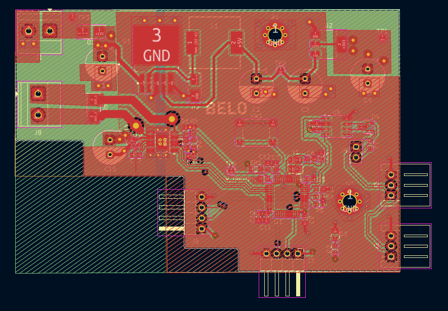
|
3D render 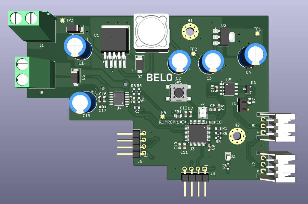
|
AS5600_Encoder_Node|
PCB layout 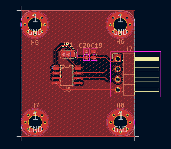
|
3D render 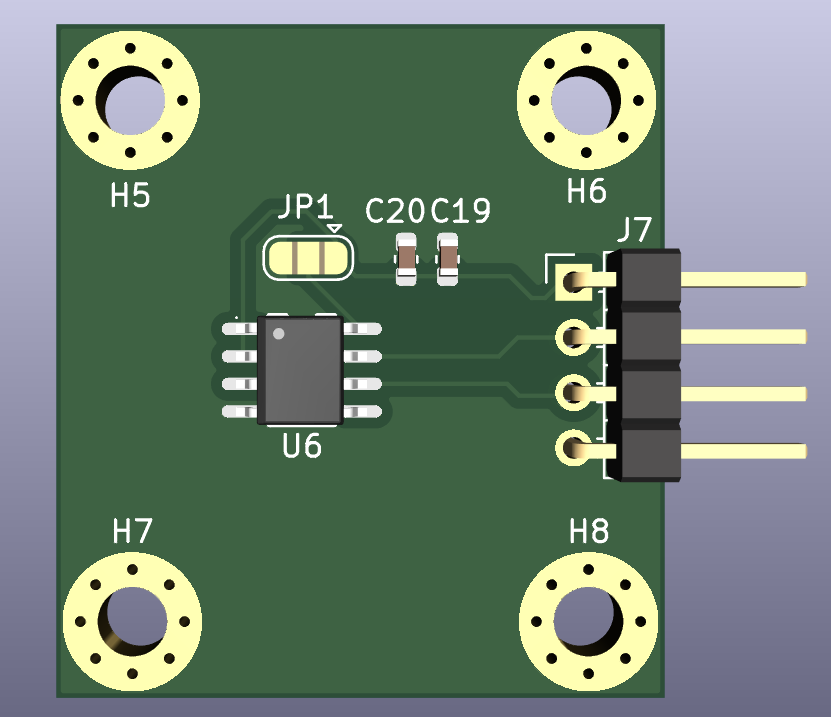
|
.
├── README.md
├── LICENSE
├── docs/                                       Design documentation
│   ├── CAN_Motor_Controller_Node_Spec.md           Full BOM, design decisions, CAN protocol, pin map
│   └── CAN_Motor_Controller_Node_PCB_Layout_Guidelines.md   Placement, routing, plane strategy, DRC targets
└── hardware/
    ├── motor_controller/                       Main CAN motor controller node
    │   ├── motor_controller.kicad_pro/.kicad_sch/.kicad_pcb/.kicad_prl
    │   ├── PCB_design.png                          PCB layout screenshot
    │   ├── hardware_design.png                     3D render
    │   └── manufacturing/
    │       ├── gerbers/                            Gerber + drill files
    │       └── motor_controller-gerbers.zip         Fab-ready zip (JLCPCB format)
    └── AS5600_Encoder_Node/                    AS5600 magnetic encoder sub-PCB
        ├── AS5600_Encoder_Node.kicad_pro/.kicad_sch/.kicad_pcb/.kicad_prl
        ├── PCB_design.png                          PCB layout screenshot
        ├── hardware_design.png                     3D render
        └── manufacturing/
            ├── gerbers/
            └── AS5600_Encoder_Node-gerbers.zip
All KiCad projects are KiCad 8+ format.
motor_controller| Subsystem | Part | Notes |
|---|---|---|
| MCU | STM32F103C8T6 (LQFP-48) | 72 MHz, bxCAN, runs all 3 PID loops + CAN stack |
| Clock | 8 MHz HSE crystal, C_L = 20 pF | Required for reliable 500 kbps CAN bit timing (HSI is too loose) |
| Motor driver | DRV8874 (HTSSOP-16, PowerPAD) | Integrated current sense (IPROPI) and cycle-by-cycle current chopping — no external shunt/amplifier needed |
| Power stage | LM2596S-5V (buck) → AMS1117-3.3 (LDO) | Two-stage: switching for efficiency, then linear to give the current-sense ADC a clean reference |
| CAN transceiver | SN65HVD230 (SOIC-8) | 3.3V-only, high-speed mode, NUP2105L TVS array for bus ESD protection |
| Encoder | AS5600 (on its own sub-PCB) | 12-bit absolute angle over I²C — see below |
| Actuator | JGA25-370, 12V, 133 RPM, 20 kg·cm | Brushed DC gearmotor, 1:78 gearbox |
I_TRIP, VREF divider-set), cycle-by-cycle chopping| Frame | Direction | ID | Payload |
|---|---|---|---|
| Command | host → node | 0x100 + node_id | float32 setpoint, uint8 mode (0=position, 1=speed, 2=current) |
| Telemetry | node → host | 0x200 + node_id | float32 position, uint16 current (mA), uint8 fault flags |
node_id is assigned in firmware at flash time — no address jumpers on the
board.
docs/CAN_Motor_Controller_Node_Spec.md).manufacturing/).J1/J7 connector — both
footprints were placed independently.AS5600_Encoder_NodeA minimal breakout for the bare AS5600 magnetic rotary position sensor (SOP-8), designed specifically to avoid the double-pull-up problem that off-the-shelf AS5600 modules introduce.
| Item | Detail |
|---|---|
| Sensor | AS5600 (SOP-8), 12-bit absolute angle over I²C |
| Power wiring | VDD5V and VDD3V3 tied together, fed from the main board's 3.3V rail (required for correct 3.3V single-supply operation per datasheet) |
| Decoupling | 100 nF + 10 µF in parallel across the tied VDD node → GND (matches datasheet Fig. 13, 3.3V-mode) |
| Direction select | 3-pad solder jumper (DIR: GND = CW-increasing, VDD = CCW-increasing) — bridged at assembly time once motor orientation is known |
| Link to main board | JST-SH, 1.0 mm pitch, 4-position — carries +3V3, SCL, SDA, GND |
| Mounting | Glued flat to the motor's rear shaft-stub end face, read through a 1.0–1.5 mm air gap by a 6 mm diametric NdFeB magnet |
| Encoder resolution | 4096 counts/rev at the motor shaft → 319,488 counts/rev at the JGA25-370's output shaft (through its 1:78 gearbox) |
The AS5600 mounting bracket (clamp-style, sized to the motor's 25 mm body OD)
is specified mechanically in docs/CAN_Motor_Controller_Node_Spec.md
but deliberately not finalized until the physical sub-PCB and motor are in
hand to confirm dimensions.
| Document | Covers |
|---|---|
docs/CAN_Motor_Controller_Node_Spec.md | Full BOM with sourcing/pricing notes, design-decision rationale, CAN protocol definition, STM32 pin assignment tracker, CAN-adapter companion tool, AS5600 mounting bracket spec |
docs/CAN_Motor_Controller_Node_PCB_Layout_Guidelines.md | Trace sizing, via strategy, floorplan, placement rules, ground/power plane strategy, CAN routing, thermal, DRC targets, pre-routing checklist |
Full detail on each step, including the CAN-USB adapter's own BOM, wiring,
and firmware plan, is in docs/CAN_Motor_Controller_Node_Spec.md.
Both boards are designed for JLCPCB (4-layer main board, 2-layer sub-PCB).
Ready-to-upload gerber/drill packages are checked in under each board's
manufacturing/ folder. Re-export from KiCad's Plot dialog after any layout
change rather than editing the checked-in gerbers by hand.
motor-control-board — KiCad, CC-BY, near-identical spec; source for the CAN daisy-chain connector and termination-jumper approach.MIT — see LICENSE.
This repository contains PCB hardware design files (KiCad schematics, layouts, and manufacturing outputs) alongside documentation. The MIT License is applied for simplicity and consistency with the author's other portfolio repositories; no warranty is made or implied about the fitness of any hardware design herein for use with live mains, high-current, or safety-critical applications. Build and operate at your own risk.
| Qty | Value | Footprint | References |
|---|---|---|---|
| 8 | 100nF | Capacitor_SMD:C_0603_1608Metric | C7, C8, C9, C10, C12, C13, C16, C18 |
| 4 | TestPoint | TestPoint:TestPoint_Pad_D1.5mm | TP1, TP2, TP3, TP4 |
| 2 | 10k | Resistor_SMD:R_0603_1608Metric | R1, R3 |
| 2 | 20pF | Capacitor_SMD:C_0603_1608Metric | C5, C6 |
| 2 | 220uF | Capacitor_THT:CP_Radial_D8.0mm_P3.50mm | C2, C15 |
| 2 | 4.7k | Resistor_SMD:R_0603_1608Metric | R8, R9 |
| 2 | MountingHole | MountingHole:MountingHole_3.2mm_M3_Pad_Via | H1, H2 |
| 2 | SS34 | Diode_SMD:D_SMA | D1, D2 |
| 1 | 0.1uF | Capacitor_SMD:C_0603_1608Metric | C14 |
| 1 | 10uF | Capacitor_THT:CP_Radial_D8.0mm_P3.50mm | C3 |
| 1 | 120 | Resistor_SMD:R_0603_1608Metric | R7 |
| 1 | 1k | Resistor_SMD:R_0603_1608Metric | R2 |
| 1 | 2.2K | Resistor_SMD:R_0603_1608Metric | R_IPROPI1 |
| 1 | 20k | Resistor_SMD:R_0603_1608Metric | R6 |
| 1 | 22nF | Capacitor_SMD:C_0603_1608Metric | C17 |
| 1 | 22uF | Capacitor_THT:CP_Radial_D8.0mm_P3.50mm | C4 |
| 1 | 3.3k | Resistor_SMD:R_0603_1608Metric | R4 |
| 1 | 4.7uF | Capacitor_SMD:C_0603_1608Metric | C11 |
| 1 | 470uF | Capacitor_THT:CP_Radial_D8.0mm_P3.50mm | C1 |
| 1 | 5.1k | Resistor_SMD:R_0603_1608Metric | R5 |
| 1 | 68uH | external_footprint:IND-SMD_L12.3-W12.3_SMDRI127 | L1 |
| 1 | 8MHz3225-SMD | external_footprint:CRYSTAL-SMD_4P-L3.2-W2.5-BL | Y1 |
| 1 | AMS1117-3.3 | Package_TO_SOT_SMD:SOT-223-3_TabPin2 | U2 |
| 1 | Bridge | Connector_JST:JST_XH_S3B-XH-A_1x03_P2.50mm_Horizontal | J2 |
| 1 | DRV8874PWPR | external_footprint:HTSSOP-16_L5.0-W4.4-P0.65-LS6.4-BL-EP | U4 |
| 1 | D_TVS | Diode_SMD:D_SMA | D5 |
| 1 | EN | Connector_PinHeader_2.54mm:PinHeader_1x02_P2.54mm_Vertical | J4 |
| 1 | External | Connector_JST:JST_XH_S3B-XH-A_1x03_P2.50mm_Horizontal | J5 |
| 1 | FerriteBead | Inductor_SMD:L_0805_2012Metric | FB1 |
| 1 | J_Motor | TerminalBlock_Phoenix:TerminalBlock_Phoenix_MKDS-1,5-2-5.08_1x02_P5.08mm_Horizontal | J8 |
| 1 | LED | LED_SMD:LED_0805_2012Metric | D3 |
| 1 | LM2596S-5 | Package_TO_SOT_SMD:TO-263-5_TabPin3 | U1 |
| 1 | NUP2105L | Package_TO_SOT_SMD:SOT-23 | D4 |
| 1 | SN65HVD230 | Package_SO:SOIC-8_3.9x4.9mm_P1.27mm | U5 |
| 1 | ST-link_connector | Connector_PinHeader_2.54mm:PinHeader_1x04_P2.54mm_Horizontal | J3 |
| 1 | STM32F103C8Tx | Package_QFP:LQFP-48_7x7mm_P0.5mm | U3 |
| 1 | SW_Push | Button_Switch_SMD:SW_SPST_PTS645Sx43SMTR92 | SW1 |
| 1 | Screw_Terminal_01x02 | TerminalBlock_Phoenix:TerminalBlock_Phoenix_MKDS-1,5-2-5.08_1x02_P5.08mm_Horizontal | J1 |
| 1 | Sub_PCB | Connector_PinHeader_2.54mm:PinHeader_1x04_P2.54mm_Horizontal | J6 |
mohamed-belal-10/can-motor-controller-node
CAN-connected closed-loop DC motor controller node — KiCad hardware (STM32F103, DRV8874, SN65HVD230) with an AS5600 encoder sub-PCB

aramder/orc
Open replacement controller board for surplus Motorola PMUN1046A relay boxes: ESP32-C3, CANopen control, 10 x 15 A channels. Independent project, not affiliated with Motorola Solutions.

Akinlatauto19/STM32-Automotive-BCM-Development-Board
Automotive Body Control Module (BCM) development board designed around an STM32 microcontroller, featuring relay-based automotive outputs, power management, protection circuitry, and a custom KiCad PCB.

NGOQUOC98/ESP32_MODBUS_PCB_MASTER
This project was in development phase - we will remove this remark after release


vyrubaev/TV-Lift-Controller
TVLift Controller is an intelligent controller for TV lift and lower mechanisms, based on the ESP32 microcontroller.


lansalot/AOG_Dev
Like AgOpenGPS but not. This version is constantly under development.

Barbedx/MeganeCAN
ESP32-based CAN-bus companion for Renault Megane 2 infotainment displays.
It measures 92.1 × 62.8 mm and has 4 copper layers, 1.6 mm thick.
55 parts, built around the SN65HVD230D, LM2596S-5.0, AMS1117-3.3 and SS34. The full list of its parts is on this page, with links to each part's symbol and footprint where PCBKit's library has them.
From the mohamed-belal-10/can-motor-controller-node repository on GitHub, at the commit this page was made from: the board is hardware/motor_controller/motor_controller.kicad_pcb and its schematic hardware/AS5600_Encoder_Node/AS5600_Encoder_Node.kicad_sch. PCBKit opens the board in the browser, with nothing to install.
Its repository publishes it under the MIT licence: you may reuse it on that licence's terms (keep the author's notice, and for a copyleft licence share your changes alike).